GRAS 67HA User manual

Instruction Manual
www.gras.dk
LI0106 – 10 November 2017
G.R.A.S. 67HA 1 m Sound Power Hemisphere Kits

2LI0106 – 10 November 2017
Revision History
Revision Date Description
1 11 August 2014 First release
2 28 October 2015 Caution about the use of non-G.R.A.S. cables added to the
section “Mounting Microphone Sets and Cables”
3 10 December 2015 Number of cable clips included in the delivery corrected.
4 15 August 2016 Configuration naming on page 25 corrected (67HA-03 and
67HA-08)
5 4 July 2017 42AG substituted for the obsolete 42AB
6 10 November 2017 Color coding for 4 and 10 channel versions updated
Copyright Notice
© 2016-17 G.R.A.S. Sound & Vibration A/S
www.gras.dk
Any technical documentation that is made available by G.R.A.S. is the copyrighted work of
G.R.A.S. and is owned by G.R.A.S.
The content in this document is subject to change without notice. G.R.A.S. Sound & Vibration A/S
is not liable or responsible for any errors or inaccuracies that may appear in this document.
Trademarks
Any product names mentioned in this document may be trademarks or registered trademarks of
their respective companies and are hereby acknowledged.

3
LI0106 – 10 November 2017
Contents
Introduction.................................................................................. 5
Standards ................................................................................................ 5
Applications .............................................................................................. 5
Plug & Play .............................................................................................. 5
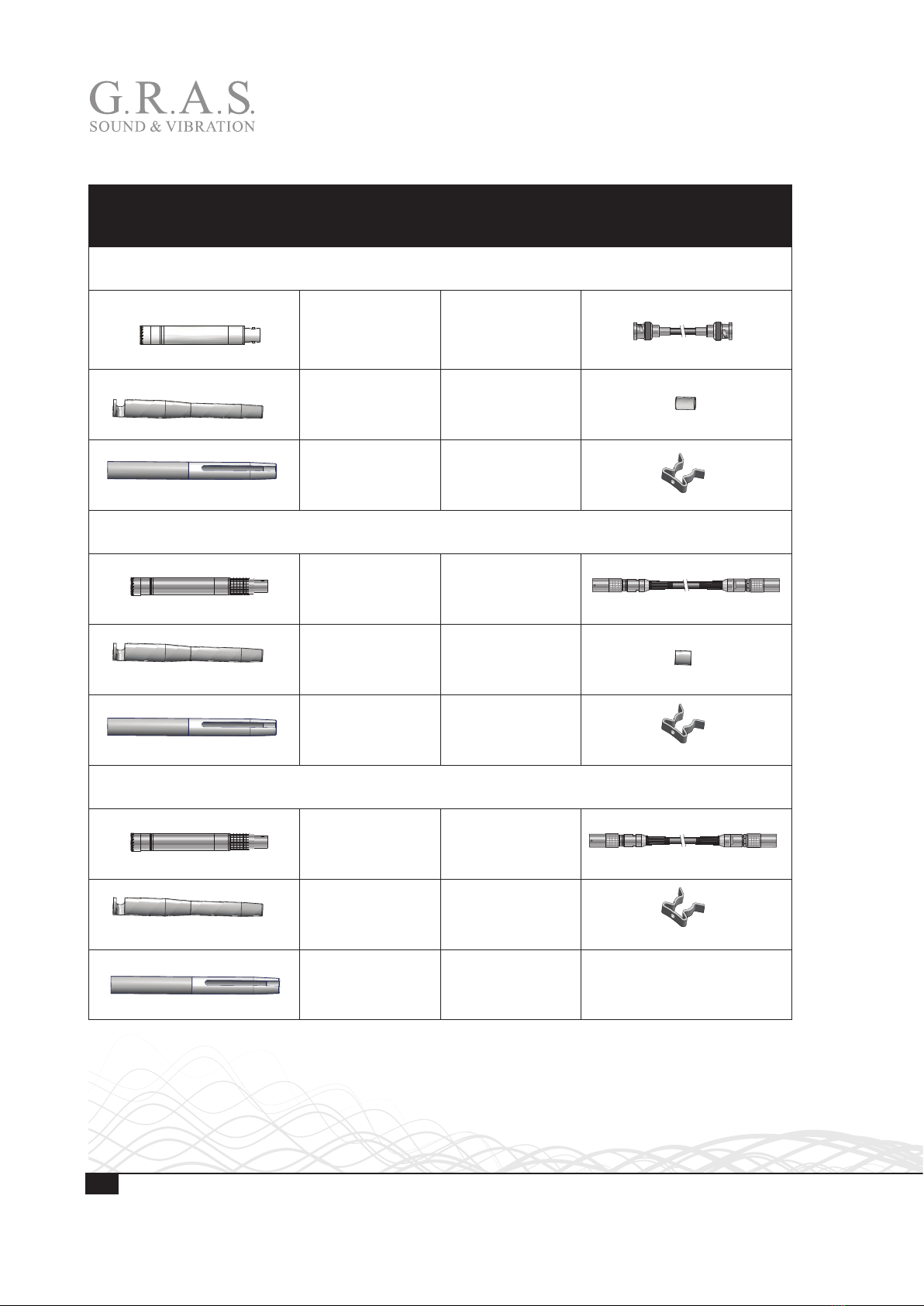
Holders and Cables ................................................................................... 5
Delivered Items for 1 m Hemisphere ................................................. 6
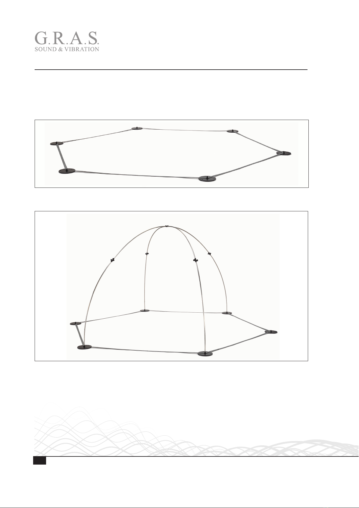
Hemisphere Structure................................................................................. 6
4-channel Configurations ............................................................................ 7
10-channel Configurations .......................................................................... 8
20-channel Configurations .......................................................................... 9
Assembling the Hemisphere – Overview........................................... 10
Assembling the Hemisphere Structure ............................................. 12
Introduction ............................................................................................. 12
Assembling the A-Layer (Bottom) ............................................................. 14
Assembling the B-Layer (Top) .................................................................... 15
Assembling the Circle ............................................................................... 16
Finishing the Assembly of the Structure ...................................................... 17
Mounting Microphone Sets and Cables ............................................ 18
Mounting the Microphone Holders ............................................................ 18
Mounting Microphone Sets and Cables ....................................................... 21
Technical Specifications................................................................ 22
Ordering Information.................................................................... 23
4-Channel Hemispheres .......................................................................... 23
10-Channel Hemispheres ......................................................................... 24
20-Channel Hemispheres ......................................................................... 25
Accessories ............................................................................................. 26
Calibration, Warranty and Service................................................... 27
Verification and Calibration ....................................................................... 27
Warranty................................................................................................. 27
Service and Repairs.................................................................................. 27

4LI0106 – 10 November 2017

5
LI0106 – 10 November 2017
Introduction
If you have ever tried to configure and use a sound power setup based on microphones mounted
on single tripods around your DUT, you will surely appreciate G.R.A.S.’ new sound power hemi-
sphere. The hemisphere will hold and position the measurement microphones according to the
standards and has been designed with focus on your workflow; it is very easy to assemble and
it is easy to position and access the DUT. Furthermore, in best G.R.A.S. tradition it is optimized
acoustically for correct and repeatable measurement data.
The structure is made portable to achieve a high degree of freedom of location. This, combined
with the easy, tool-less assembly in minutes, enables you to save expensive hemi-anechoic
chamber time and to offer on-site sound power diagnostics.
Standards
The G.R.A.S. 67HA 1 m Sound Power Hemisphere is compliant with the ISO 3744, 3745
and 3746 (ANSI S12.54, S12.55, S12.56) standards and accommodate for 4, 10 and 20
microphone positions. These are clearly marked to ease the mounting and maintain measurement
repeatability.
Applications
Depending on the size and the emitted acoustic level of the DUT, the hemisphere will allow
sound power measurements on everything from small sized personal electronics to office ma-
chines and IT products, household appliances, power tools and smaller engines. The only restric-
tion is that the characteristic dimension of the DUT may be no more than half the measurement
radius. See the aforementioned standards for further details.
Plug & Play
The microphone sets can be connected directly to all professional measurement systems and are
as indicated available for both CCP and 7-pin LEMO inputs. If your system platform supports
intelligent transducers according to IEEE 1451.4 (TEDS), the system can be set up to identify the
microphone properties and position in the array.
Holders and Cables
The pre-configured hemispheres are delivered with microphone set holders that will fit all 3
microphone types. Respective cables and cable clips are included.

6LI0106 – 10 November 2017
Delivered Items for 1 m Hemisphere
The G.R.A.S. 67HA 1 m Hemisphere is delivered in two cases, one containing the parts for the
structure, microphone holders, cables and cable clips, the other containing the parts for configur-
ing the hemisphere with microphone sets and cables.
It can be ordered for delivery in two flight cases, for further information, refer to “Accessories” on
page 26.
Hemisphere Structure
Delivered Items for 1 m Hemisphere Structure
6-pole Top
Connecting Piece
RA0254
4-pole
Connecting Piece
6 x RA0255
Vertical Pole
6 labeled A1 to A6
6 labeled B1 to B6
Horizontal Pole
6 x GR1560K
Foot
6 x RA0253
Bottom Strip
6 x RA0292
Finger Screws
(spare, 5 of each) for:
Microphone Holders and
Connecting Pieces
Strip Set for
Center Location
RA0293
GS0635
B ( 1 :2 )
C ( 1 : 1 )
B
GS0636_K05
A ( 1 : 1 )
B ( 1:1 )
A
B

7
LI0106 – 10 November 2017
4-channel Configurations
Delivered Microphones and Accessories for 4-Channel Configuration
ISO 3746:2010 / ANSI S12.56
G.R.A.S. 67HA-04 with CCP Microphone Sets
½" CCP
Microphone Set
4 x 46AE
10 m Cable,
BNC to BNC
4 x AA0037
Microphone Holder
incl. finger screw
3 x RA0259
Spacer for
Microphone Holder,
28 mm
4 x GR1572
Top Microphone
Holder
RA0261
Cable Clip
50 x KE0130
G.R.A.S. 67HA- 01 with LEMO Microphone Sets
½" LEMO
Microphone Set
4 x 46AF
10 m Cable
LEMO to LEMO
4 x AA0009
Microphone Holder
incl. finger screw
3 x RA0259
Spacer for
Microphone Holder,
18 mm
4 x GR1571
Top Microphone
Holder
RA0261
Cable Clip
50 x KE0130
G.R.A.S. 67HA-07 with Low Noise Microphone Sets
½" Low-noise
Microphone Set
4 x 40HL
10 m Cable,
LEMO to LEMO
4 x AA0009
Microphone Holder
incl. finger screw
3 x RA0259
Cable Clip
50 x KE0130
Top Microphone
Holder
RA0261
F-F ( 1 : 2 )
F
F
198
28
18 188
170
F-F ( 1 : 2 )
F
F
198
28
18 188
170
F-F ( 1 : 2 )
F
F
198
28
18 188
170
F-F ( 1 : 2 )
F
F
198
28
18 188
170
F-F ( 1 : 2 )
F
F
198
28
18 188
170

8LI0106 – 10 November 2017
10-channel Configurations
F-F ( 1 : 2 )
F
F
198
28
18 188
170
F-F ( 1 : 2 )
F
F
198
28
18 188
170
F-F ( 1 : 2 )
F
F
198
28
18 188
170
F-F ( 1 : 2 )
F
F
198
28
18 188
170
F-F ( 1 : 2 )
F
F
198
28
18 188
170
Delivered Microphones and Accessories for 10-Channel Configuration
ISO 3744:2010 / ANSI S12.54
G.R.A.S. 67HA-05 with CCP Microphone Sets
½" CCP
Microphone Set
10 x 46AE
10 m Cable,
BNC to BNC
10 x AA0037
Microphone Holder
incl. finger screw
9 x RA0259
Spacer for
Microphone Holder,
28 mm
10 x GR1572
Top Microphone
Holder
RA0261
Cable Clip
50 x KE0130
G.R.A.S. 67HA- 02 with LEMO Microphone Sets
½" LEMO
Microphone Set
10 x 46AF
10 m Cable
LEMO to LEMO
10 x AA0009
Microphone Holder
incl. finger screw
9 x RA0259
Spacer for
Microphone Holder,
18 mm
10 x GR1571
Top Microphone
Holder
RA0261
Cable Clip
50 x KE0130
G.R.A.S 67HA-08 with Low Noise Microphone Sets
½" Low-noise
Microphone Set
10 x 40HL
10 m Cable,
LEMO to LEMO
10 x AA0009
Microphone Holder
incl. finger screw
9 x RA0259
Cable Clip
50 x KE0130
Top Microphone
Holder
RA0261

9
LI0106 – 10 November 2017
20-channel Configurations
F-F ( 1 : 2 )
F
F
198
28
18 188
170
F-F ( 1 : 2 )
F
F
198
28
18 188
170
F-F ( 1 : 2 )
F
F
198
28
18 188
170
F-F ( 1 : 2 )
F
F
198
28
18 188
170
F-F ( 1 : 2 )
F
F
198
28
18 188
170
Delivered Microphones and Accessories for 20-Channel Configuration
ISO 3745:2010 / ANSI S12.55
G.R.A.S. 67HA-06 with CCP Microphone Sets
½" CCP
Microphone Set
20 x 46AE
10 m Cable,
BNC to BNC
20 x AA0037
Microphone Holder
incl. finger screw
20 x RA0259
Spacer for Micro-
phone Holder,
28 mm
20 x GR1572
Cable Clip
50 x KE0130
G.R.A.S. 67HA-03 with LEMO Microphone Sets
½" LEMO
Microphone Set
20 x 46AF
10 m Cable
LEMO to LEMO
20 x AA0009
Microphone Holder
incl. finger screw
20 x RA0259
Spacer for Micro-
phone Holder,
18 mm
4 x GR1571
Cable Clip
50 x KE0130
G.R.A.S 67HA-09 with Low Noise Microphone Sets
½" Low-noise
Microphone Set
20 x 40HL
10 m Cable,
LEMO to LEMO
20 x AA0009
Microphone Holder
incl. finger screw
20 x RA0259
Cable Clip
50 x KE0130

10 LI0106 – 10 November 2017
Assembling the Hemisphere – Overview
The G.R.A.S. 1 m Hemisphere for sound power measurements consists of a basic structure
common to all applications. This structure can be configured for 4-channel, 10-channel and
20-channel measurements. Below is shown a quick overview of the assembly of the hemisphere
and the mounting of microphones for a 10-channel configuration. A detailed description of the
assembly is given in the following sections.
Fig. 1. The basic hexagonal layer.
Fig. 2. The basic layer and four out of six legs of the vertical structures assembled.

11
LI0106 – 10 November 2017
Fig. 3. The assembled structure ready for configuration.
Fig. 4. The hemisphere structure mounted with microphones and cables for a 10-channel setup.

12 LI0106 – 10 November 2017
Assembling the Hemisphere Structure
Introduction
The Hemisphere consists of a ground layer and vertical and horizontal poles:
• The ground layer consists of six feet and six connecting strips.
• The A-layer consists of six vertical poles attached to the feet, labeled A1 to A6.
• The horizontal circle consists of six poles and six 4-pole connecting pieces.
• The top-B layer consists of six vertical poles labeled B1 to B6, and a 6-pole connecting piece.
It can be assembled without tools by one person. All connections are fastened with finger screws.
B1
A1
B-layer (blue)
A-layer (green)
Horizontal circle (red)
Ground layer (black)
A2
B2
Fig. 5. The hemisphere structure.
The vertical poles and the top connecting
piece are furnished with colored bolts marking
the positions for the microphones according to
the ISO and ANSI standards for sound power
measurements.
The yellow bolts indicate the positions for
4-channel measurements, the blue for
10-channels and the red for 20 channels.
Important. To ensure correct positioning of
the colored bolts you must:
• Mount the poles A1 to A6
counterclockwise.
• Align the A-layer and the B-layer (A1 with
B1 and so on).
• Ensure that the labeled end of the poles
point upwards.
A ( 1 : 1 )
B ( 1:1 )
A
B
Positioning bolt
Fig. 6. The Microphone Holders are positioned over
colored bolts mounted on the vertical poles.

13
LI0106 – 10 November 2017
Assembling the Ground Layer
E ( 0,4 : 1 )
E
Strip for ground layer
Hole for securing the foot
to the floor, 6 mm (not
included)
Finger screw for securing
the vertical pole
Tube for strips and
poles. Outer diam-
eter for strips, inner
for vertical poles of
A-layer
Fig. 7. A Hemisphere foot showing the details for connections to vertical poles and strips.
1. Remove the finger screws from the tubes of the feet.
2. Slide two strips down over each of the vertical tubes until the circle is complete.
3. Mount the strip set for center location over two of the feet.
4. Mount the screws again (to avoid loosing them). Do not tighten, but leave room for the vertical
poles to slide into the holes.
Strip assembly for center location
Fig. 8. The finished ground layer.

14 LI0106 – 10 November 2017
Assembling the A-Layer (Bottom)
A2
A1
A6
A3
A4
A5
Fig. 9. The A-layer vertical poles mounted in the feet.
Mounting the Vertical Poles and 4-pole Connecting Pieces
1. Slide the vertical pole labeled A1 with the label end upwards into one of the feet.
2. Tighten the finger screw lightly to assure some clearance for angular adjustment of poles and
connecting pieces in the next steps. See Fig. 10-1.
3. Repeat steps 1 & 2 for the poles A2 to A6 in counterclockwise sequence, as shown in Fig. 9.
4. Slide the six 4-pole connecting pieces onto six the pole ends (Fig. 10-2).
5. Tighten the lower finger screws lightly (Fig. 10-3).
Recess
for finger
screw
A ( 1 : 1 )
A
2 3
A ( 1 : 1 )
A
A ( 1 : 1 )
A
Slide all 4-pole connecting
pieces onto the six pole ends
Tighten the finger screws
lightly
1
Slide all six poles into the six
feet and tighten lightly
Recess
for finger
screw
A ( 1 : 1 )
A
Fig. 10. Mounting the lower poles and the 4-pole connecting pieces.

15
LI0106 – 10 November 2017
Assembling the B-Layer (Top)
A1
B1
Fig. 11. The 1m Hemisphere with all vertical poles assembled.
Mounting the Vertical Poles and the top Connecting Piece
1. Slide the six vertical poles B1 to B6 into the 4-pole connecting pieces with the labeled end
pointing upwards, and tighten lightly. See Fig. 12-1. The pole labeled B1 must be flush with
A1 and so on.
2. Slide the poles into the top connecting piece and tighten the finger screws lightly. See Fig.
12-2.
B6
A ( 1 : 1 )
A
B1
B2
B3
B4
B5 B3
A ( 1 : 1 )
A
1 2
Repeat to complete all six connections
Slide the poles into the 4-pole connecting
piece and tighten the finger screws lightly
Slide the poles into the 6-pole connecting
piece and tighten the finger screws lightly
Repeat to complete all six connections
Fig. 12. Mounting the upper poles and the top 6-pole connecting piece.

16 LI0106 – 10 November 2017
Assembling the Circle
Fig. 13. First step of the assembly of the circle.
Assembling the Circle
The circle consists of six identical poles. Their purpose is solely to stabilize the structure and they
can therefore be sequenced at will. When finished, the structure will look as shown in Fig. 15.
1. Slide the poles into the 4-pole connecting pieces.
2. Tighten the finger screws lightly: Some clearance is needed for final adjustment of poles and
connecting pieces.
1 2
Slide the poles into the 4-pole
connecting pieces Tighten the finger screws lightly
Repeat to complete all six connections
Fig. 14. Assembling the circle.

17
LI0106 – 10 November 2017
Finishing the Assembly of the Structure
When all poles and connecting pieces have been assembled, you need to fine adjust the orienta-
tion of all poles and tighten all finger screws.
When mounted correctly, the hemisphere will present a smooth structure with a level horizontal
circle and smooth vertical curves. However, as all connecting pieces are straight, minor deviations
from perfect circles must be expected.
The positioning and adjustment system for the microphones makes it possible to position the
microphones very accurately in relation to the device under test. For information about fine
adjustment of the positioning of the microphones, refer to Fig. 16 and Fig. 19.
Five extra finger screws for the connecting pieces are included in the delivery, so a number of
extra screws will be in reserve when the structure has been assembled.
Fig. 15. The finished hemisphere structure.

18 LI0106 – 10 November 2017
Mounting Microphone Sets and Cables
Mounting the Microphone Holders
The hemisphere is designed for easy and repeatable 4-channel, 10-channel and 20-channel
measurements:
• Clearly marked mounting points make it easy to mount the microphone sets in accordance with
the ISO and ANSI standards.
• A flexible mounting system with adjustable holders and fixed spacers makes it easy to mount
the microphone sets with the correct distance and angle to the hemisphere’s center.
Mounting Points
The mounting points for 4, 10 and 20 channel measurements are identified by colored M3 bolts
on the vertical poles, and – for 4 and 10 channel measurements – also on the top connecting
piece.
The mounting points for 4 channels are located according to the ISO 3746:2010 (Table B.1)
recommendation for microphone positions for a noise source over a reflecting plane. The mount-
ing points for 10 and 20 channels are located according to the ISO 3744:2010 (Table B.2) and
ISO 3745:2012 (Table E.2) recommendations for microphone positions for a broadband noise
source.
For 4 channels, positions 4, 5, 6 and 10 are marked with black bolts, the additional positions
14, 15, 16 and 20 are marked with grey bolts.
For 10 channels, positions 1 to 10 are marked with blue and black positioning bolts, the addi-
tional positions 11 to 20 with yellow and grey bolts.
For 20 channels, the positions 1 to 20 are marked with red bolts.
Channels Standard Key microphone positions Additional positions
4ISO 3746:2010 - Table B.1 / ANSI S12.56 – –
10 ISO 3744:2010 - Table B.2 / ANSI S12.54
20 ISO 3745:2012 - Table E.2 / ANSI S12.55 – – –

19
LI0106 – 10 November 2017
Holders and Spacers
For all configurations, the same type of microphone holder is used. Spacers of different lengths
are used to ensure that the three types of microphone sets – CCP, LEMO and LEMO Low-noise –
can be mounted with the correct distance to the center.
Microphone Set Spacer
46AE (CCP) 28 mm spacer
46AF (LEMO) 18 mm spacer
40HL (LEMO, Low Noise) No spacer
Mounting Microphone Holders on Vertical Poles
1. Remove the finger screw from the end of the microphone holder assembly and slide the holder
over the pole.
2. Slide the holder downwards until it is centered over the colored bolt.
3. Mount the finger screw and tighten it lightly.
4. Adjust the direction of the holder to point at the center of the hemisphere and tighten the
finger screw.
1
A ( 1 : 1 )
B ( 1:1 )
A
B
2
A ( 1 : 1 )
B ( 1:1 )
A
B
3
A ( 1 : 1 )
B ( 1:1 )
C ( 1 : 1 )
A
B
C
4
A ( 1 : 1 )
B ( 1:1 )
A
B
A ( 1 : 1 )
B ( 1:1 )
A
B
A ( 1 : 1 )
B ( 1:1 )
A
B
A ( 1 : 1 )
B ( 1:1 )
A
B
Slide the microphone holder
onto the vertical pole
Slide the microphone holder
downwards over the colored
positioning bolt
Mount the finger screw Adjust the direction
and tighten the finger
screw
Fig. 16. Attaching a microphone holder to a vertical pole.

20 LI0106 – 10 November 2017
Mounting a Microphone Holder at the Top Center
Fig. 17. For 4 and 10-channel configurations, the top microphone holder is attached to the top connector.
1. Screw the long top spacer onto the stud screw on the 6-pole connecting piece.
2. Slide a spacer onto the lower part of the Microphone Holder. For CCP Microphone sets, a 28
mm spacer is needed, for LEMO microphone sets an 18 mm spacer is needed. For the LEMO
low-noise microphone sets, no spacer is needed.
3. Screw the lower part into the upper part.
1 3
2
Stud screw
Top spacer
Spacer
(18 mm,
28 mm or none)
Lower part
Fig. 18. Mounting and assembling the Top Microphone Holder.
Table of contents
Other GRAS Speakers System manuals