9
English
Belt drive maintenance (CT-series)
• Check the belt drive.
To inspect the belt, the beltcover must be removed (see
fig. 10, CT600).
Make sure that no teeth are damaged or worn. Correct
tension is when the belt can be twisted about 45° (see fig.
11).
If adjustment is required, loosen the flange bolts and in-
crease or decrease the tension by adjusting the the bolt
under the motor. Tighten the flange bolts and recheck the
belt tension.
Function test - general guidance
Important!
Keep hands and loose objects away from thruster
whenoperating.
Important!
In general, function testing requires running in wa-
ter, to achieve normal load. With no load, damage
to the motor can be the result, by over running at
too high RPM., because the motor will continue run-
ning some time after turning off the current. This
might cause induction of current and burned relay.
• If running in water not is possible, start the motor by
giving just a short impulse and be sure that the motor
has stopped completely before running the opposite
way.
• When checking the voltage on the control unit,
running in water will give the needed load to get
correct result. To check for any kind of leakage, testing
in water is required.
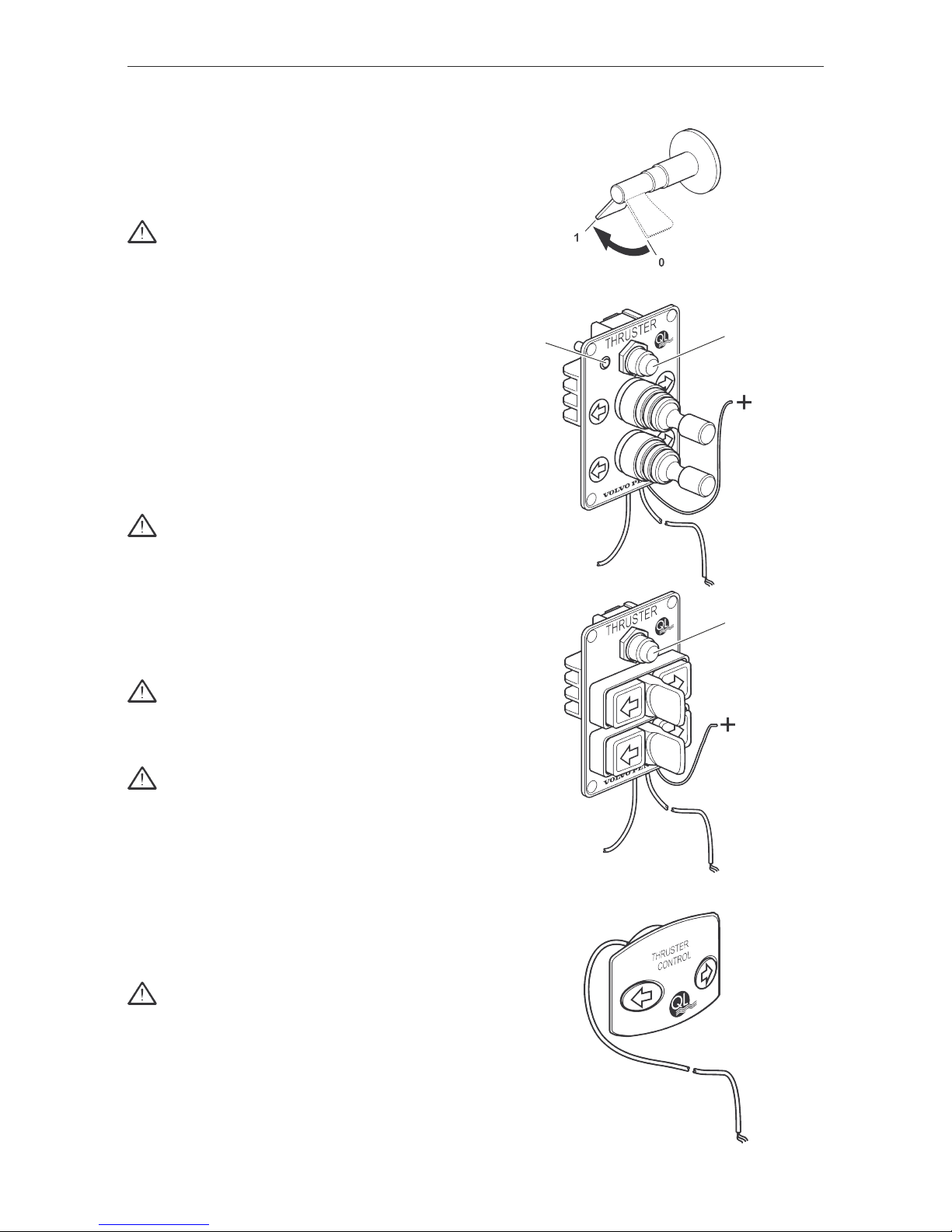
Joystick / Thruster control panel check
• Check Joystick / Thruster control panel function.
If malfunction, the following tests will show if the Joystick/
Thruster control panel is working and if the control unit is
working.
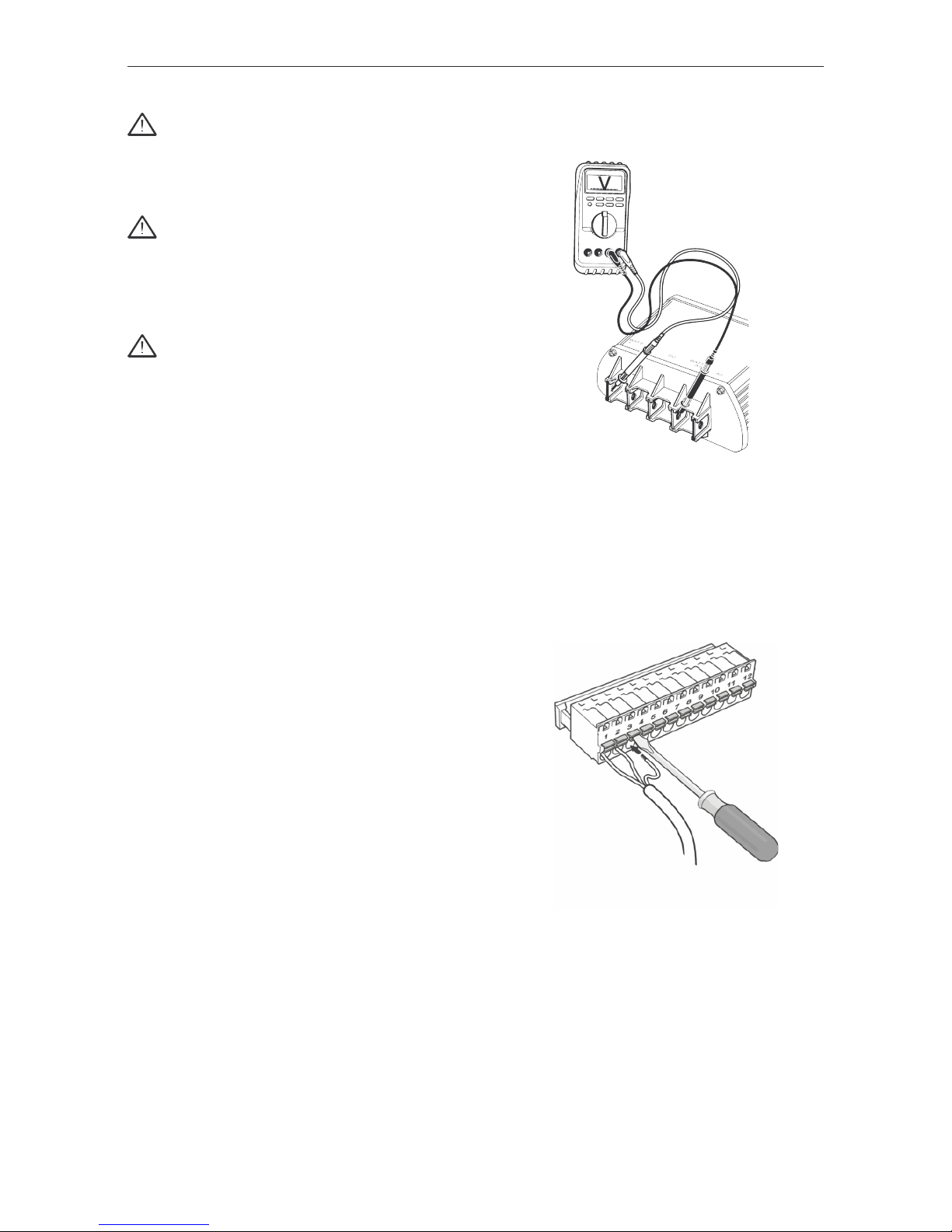
1.
• Check that you have thruster operation (different
directions) by short-circuiting terminal 1 and 2 or 2
and 3 on the control unit.
Note! Can also be tested via the test buttons on the cir-
cuit card. See fig. 12
2.
If you have thruster operation via the control unit / circuit
card, please check the joystick and the joystick cable for
faults.
3.
If there is no thruster operation via the control unit / cir-
cuit card, please check fuse, battery power, electric motor,
main relay and circuit card. (The power supply)
4.
If the electric motor runs and there is no thrust, please
check driving pins and propeller(s).
If the fault still remains, please contact your service dealer.
Fig. 12
Fig. 11
Fig. 10