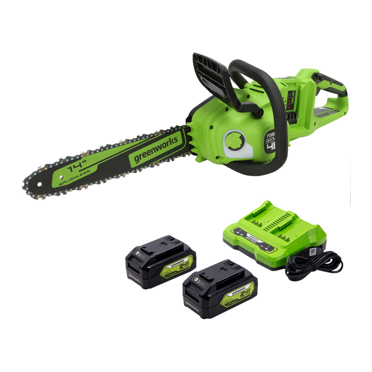
GreenWorks Tools GD60CS40 User manual

60V Brushless Chainsaw
DE
ES
IT
FR
PT
NL
RU
FI
SV
NO
DA
PL
CS
SK
SV
HR
HU
RO
BG
EL
AR
TR
HE
LT
LV
ET
EN
USER’S MANUAL
USER’S MANUAL
USER’S MANUAL
USER’S MANUAL
USER’S MANUAL
USER’S MANUAL
USER’S MANUAL
USER’S MANUAL
USER’S MANUAL
USER’S MANUAL
USER’S MANUAL
USER’S MANUAL
USER’S MANUAL
USER’S MANUAL
USER’S MANUAL
USER’S MANUAL
USER’S MANUAL
USER’S MANUAL
USER’S MANUAL
USER’S MANUAL
USER’S MANUAL
USER’S MANUAL
USER’S MANUAL
USER’S MANUAL
USER’S MANUAL
USER’S MANUAL
USER’S MANUAL
1
11
1
1
11
1
1
11
1
1
11
1
1
11
1
1
11
1
1
11
1
1
11
1
1
11
1
2001807
GD60CS40
60V Brushless Chainsaw

English (original instructions)
EN DE ES IT FR PT NL RU FI SV NO DA PL CS SK SL HR HU RO BG EL AR TR HE LT LV ET
SPECIFICATIONS
Voltage 60V DC
No load speed 5000±10% rpm
Guide bar length 16 in. (406 mm)
Chain stop < 3s
Chain oil tank capacity 170 ml
Weight
(with 4Ah battery pack)
Max 4.3kg ( without guide
bar and saw chain )
Emission sound
pressure level LpA
81.5dB(A)
Uncertainty KpA 3.0dB(A)
Sound power level LwA 94.7dB(A)
Guaranteed sound
power level LwA(G)
97dB(A)
Vibration total value ah 2.5m/s2
Uncertainty KwA 1.5m/s2
REMARKS:
The declared vibration value has been measured with
a standard test method and may be used to compare
one tool with another.
The declared vibration value may be used in a
preliminary assessment of exposure.
WARNING
The actual vibration values during use of the tool can
be different from the above stated and depend on the
use of the tool; and the need to identify safety measures
to protect the operator are based on an estimation of
exposure in the actual conditions of use (taking account
all parts of the operating cycle such as the times when
the tool is switched off and when it is running idle in
addition to the trigger time).
CHAIN & BAR INFORMATION
2001807
Manufacture Saw chain Guide bar
Oregon 91PJ056X 160SDEA041
Oregon's chain must be tted with Oregon's bar;
Trilink's chain must be tted with Tri-link's bar.
DESCRIPTION
1. Safety Lock
2. Trigger
3. Rear Handle
4. Front Handle
5. Quick View Oil Indicator
6. Oil Cap
7. Low Kickback Chain
8. Chain Brake
9. Bar
10. Sprocket cover tighten nuts
11. Chain Tensioner adjust knob
12. Wrench
13. Scabbard
14. Sprocket cover
15. Chain cover
16. Bolt for saw chain tension
17. Sprocket
18. Spike bumpers
19. Oil outlet
20. Bar groove
21. Chain drive links
22. Cutter
23. Felling direction
24. Danger zone
25. Escape route
26. Direction of fall
27. Notch
28. Felling back cut
29. Hinge
30. Limb cut
31. Keep work off ground leave support limbs until log is
cut
32. Log supported along the entire length
33. Cut from top (over buck) avoid cutting earth
34. Log supported
35. Under buck
36. Over buck
FPO

English (original instructions)
EN DE ES IT FR PT NL RU FI SV NO DA PL CS SK SL HR HU RO BG EL AR TR HE LT LV ET
37. Log supported both ends
38. Bucking a log
39. Stand on uphill side when cutting because log may
roll
ASSEMBLY
This chain saw does not require assembly, but user should
know how to assemble the guide bar and saw chain.
Check the chain tensioning and add oil as described later
in this manual before each operation.
ASSEMBLING THE GUIDE BAR AND SAW CHAIN
See gure 2 - 7
Make sure remove the battery pack from the unit. Wear
protective gloves.
Unscrew the sprocket cover tighten knob (item 10)
and remove the sprocket cover.
The saw chain should face in the direction of chain
rotation. If they face backwards, turn the loop over.
Place the chain drive links into the bar groove.
Position the chain so there is a loop at the back of
the bar.
Hold the chain in position on the bar and place
the loop around the sprocket and make sure it is
correctly mounted. Make sure the bar hole ts well
with bolt (item 16) for saw chain tension.
Replace the sprocket cover, turn the chain tension
adjust knob (item 11) clockwise until the saw chain
is properly tensioned. The guide bar must then be
pushed upwards, check chain tension again, do not
tension the chain too tight.
After the chain is well-tensioned, tighten the knob
(item 10) again.
NOTE: The saw chain is properly tensioned if, in the
middle of the guide bar, it can be lifted 3mm to 4mm from
the edge of the guide bar. Start the saw again with a new
saw chain, allowing it to run-in for 2~3 minutes.
WARNING
After the run-in time, check the chain tension and
retighten the chain if necessary.
OPERATION
For complete charging instructions, refer to the
Operator’s Manuals for your Greenwork battery pack
and charger models.
NOTE: To avoid serious personal injury, always remove
the battery pack and keep hands clear of the lock-out
button when carrying or transporting the tool.
BEFORE EACH USE CHECKING THE CHAIN
TENSION
WARNING
Remove the battery pack from the chain saw before
checking the chain tension or making adjustments to
the chain. Wear protective gloves while touching the
chain, bar or areas around the chain.
Pull the chain in the middle of the lower side of the bar
away from the bar. The gap between the cutter in the
chain and the bar should be between 3mm - 4mm.
If you need to adjust the chain tension, please refer to
the section “ADJUSTING THE CHAIN TENSION” later
in this manual.
TO INSTALL BATTERY PACK
See Figure 2.
Align the battery pack with the battery compartment
on the chain saw.
Grasp the chain saw firmly.
Push the battery pack into the battery compartment
until the latch locks into place.
You should hear a "click" once the battery is installed.
TO REMOVE BATTERY PACK
See Figure 2.
Press the battery release button on the chain saw.
This will cause the battery to raise out of the tool
slightly.
Grasp the chain saw firmly, and pull the battery pack
out of handle.
CHECKING THE CHAIN LUBRICANT
See Figure 2.
Check the amount of oil in the chain saw by looking
at the quick view oil indicator ( item 5). If the oil level
is low, follow the steps shown in section “ADDING
CHAIN & BAR LUBRICANT” of this manual.

English (original instructions)
EN DE ES IT FR PT NL RU FI SV NO DA PL CS SK SL HR HU RO BG EL AR TR HE LT LV ET
WARNING
Check the chain tension before each use of the saw.
WARNING
Never operate the chain saw without sufcient chain
lubrication as this might damage the saw and is a threat
to safety. Check the chain lubricant level before each
use!
In order to prevent kickback, please follow these safety
instructions:
Never cut with the tip of the guide bar! Be careful
when continuing from previous cuts.
Always start cutting only when the chain saw is
already running.
Make sure that the saw chain is always properly
sharpened.
Never cut through more than one branch at a time!
When lopping off branches, be careful not to touch
any other branches.
When cross-cutting, pay attention to trunks standing
very close to each other. If possible, use a sawing
trestle.
HOLDING THE CHAIN SAW
See figure 8
Always hold the chain saw with your right hand at the
rear handle and your left hand at the front handle.
Grip both handles with the thumbs and fingers encircling
the handles. Ensure that your left hand is holding the front
handle so that your thumb is underneath.
STARTING OPERATION
Before starting for operation, you should install the
battery pack in the machine.
Press the safety lock (item 1), this makes the switch
trigger operational.
Press and hold the trigger (item 2), and keep it
pressed for continued operation.
STOPPING OPERATION
Release the trigger (item 2) to stop the chain saw.
OPERATING THE CHAIN BRAKE See figure 22
Check the operating condition of the chain brake prior to
each use.
Engage the chain brake by rotating your left hand
around the front handle, allowing the back of your
hand to push the chain brake lever/hand guard
toward the bar while the chain is rotating rapidly. Be
sure to maintain both hands on the saw handles at
all times.
Reset the chain brake back into the RUN position by
grasping the top of the chain brake lever/hand guard
and pulling toward the front handle.
WARNING
If the chain brake do not stop the chain immediately, or
if the chain brake will not stay in the run position without
assistance, take the saw to an authorized service center
for repair prior to use.
USING THE CHAIN SAW
Always be sure of your footing and hold the chain saw
rmly with both hands while the motor is running.
BASIC FELLING, LIMBING, AND CROSS-CUTTING
TECHNIQUES
See gure 9
FELLING A TREE
When bucking and felling operations are being performed
by two or more persons at the same time, the felling
operation should be separated from the bucking operation
by a distance of at least twice the height of the tree being
felled. Trees should not be felled in a manner that would
endanger any person, strike any utility line or cause any
property damage. If the tree does make contact with
any utility line, the utility company should be notifi ed
immediately.
The chain saw operator should keep on the uphill side of
the terrain as the tree is likely to roll or slide downhill after
it is felled.
An escape path should be planned and cleared as
necessary before cuts are started. The escape path
should extend back and diagonally to the rear of the
expected line of fall.
Before felling is started, consider the natural lean of the
tree, the location of larger branches and the wind direction
to judge which way the tree will fall.
Remove dirt, stones, loose bark, nails, and staples from
the tree.
NOTCHING UNDERCUT (A NOTCH CUT IN A TREE TO
DIRECT THE FALL)
See Figure 10
Make the notch 1/3 in diameter of the tree, perpendicular
to the direction of falls. Make the lower horizontal notching
cut fi rst, this will help to avoid pinching of either the saw
chain or the guide bar when the second notch is being
made.
FELLING BACK CUT (THE FINAL CUT IN A TREE

English (original instructions)
EN DE ES IT FR PT NL RU FI SV NO DA PL CS SK SL HR HU RO BG EL AR TR HE LT LV ET
FELLING OPERATION, MADE ON THE OPPOSITE
SIDE OF THE TREE FROM THE NOTCHING
UNDERCUT)
See Figure 10
Make the felling back cut at least 50mm higher than the
horizontal notching cut. Keep the felling back cut parallel
to the horizontal notching cut. Make the felling back cut
so as to leave enough wood to act as a hinge. The hinge
wood keeps the tree from twisting and falling in the wrong
direction. Do not cut through the hinge. As the felling
cut gets close to the hinge, the tree should begin to fall.
If there is any chance that the tree may not fall in the
desired direction or it may rock back and bind the saw
chain, stop cutting before the felling back cut is complete
and use wedges of wood, plastic or aluminium to open the
cut and drop the tree along the desired line of fall. When
the tree begins to fall, remove the chain saw from the cut,
stop the motor, put the chain saw down, and then use the
retreat path as planned. Be alert of overhead limbs falling
and watch your footing.
LIMBING A TREE
See figure 11
Limbing is removing the branches from a fallen tree.
When limbing, leave the larger lower limbs to support the
log off the ground. Remove the small limbs in one cut.
Branches under tension should be cut from the bottom
up, to avoid binding the chain saw.
BUCKING A LOG
See figure 12 - 15
Bucking is cutting a log into lengths. It is important to
make sure your footing is fi rm and your weight is evenly
distributed on both feet. When possible, the log should be
raised and supported by the use of limbs, logs or chocks.
Follow the simple direction for easy cutting:
1. When the log is supported along the entire length, it is
cut from the top (over buck).
2. When the log is supported on one end, cut 1/3 of the
diameter from the underside (under buck). Then make the
fi nished cut by over bucking to meet the fi rst cut.
3. When the log is supported on both ends, cut 1/3 of that
diameter from the top (over buck). Then make the finished
cut by under bucking the lower 2/3 to meet the first cut.
4. When bucking on a slope, always stand on the
uphill side of the log. When cutting through, to maintain
complete control, release the cutting pressure near the
end of the cut without relaxing your grip on the chain saw
handles.
Do not let the chain contact the ground. After completing
the cut, wait for the saw chain to stop before you move
the chain saw. Always stop the motor before moving from
tree to tree.
MAINTENANCE
WARNING
Always remove the battery pack from the machine before
checking the chain tension or making adjustments to the
chain. Wear protective gloves while touching the chain,
bar or areas around the chain.
ADJUSTING THE CHAIN TENSION
See gure 2 and gure 7
Loosen the chain cover lock nuts (item 10) with the
supplied wrench. The chain cover lock nuts do not
have to be completely removed in order to adjust the
chain tension.
Rotate the chain adjustment screw(item 11)
clockwise to increase the chain tension and rotate
counterclockwise to decrease the chain tension.
Once the chain is at the desired tension, tighten the
chain cover lock nuts(item 10).
REPLACING THE BAR AND CHAIN
See Figure 3-7
Remove the battery from the chain saw.
Remove the supplied wrench(item 12) from the rear
handle (item 3).
Remove the two chain cover lock nuts (item 10) from
chain cover by rotating them counterclockwise with
the wrench.
Remove the chain cover(item 15) from the mounting
surface.
The bar and chain can now be removed by lifting it
away from the main body of the saw and releasing
the chain from the sprocket.
Remove the old chain from the bar.
Lay out the new saw chain in a loop and straighten
any kinks. The cutters should face in the direction of
chain rotation. If they face backwards, turn the loop
over.
Place the chain drive links into the bar groove.
Position the chain so there is a loop at the back of
the bar.
Hold the chain in position on the bar and place the
loop around the sprocket.
Fit the bar ush against the mounting surface so that
the bar studs are in the long slot of the bar. Ensure
that the chain is over the sprocket.
Replace the chain cover.
Remove all slack from the chain by turning the chain
adjustment screw(item 11) clockwise until the chain
seats snugly against the bar with the drive links in the
bar groove(item 20).
Lift the tip of the guide bar up to check for sag.
Release the tip of the guide bar and turn the chain
adjustment screw 1/2 turn clockwise. Repeat this
process until sag does not exist.
Hold the tip of the guide bar up and tighten the chain
cover lock nuts by turning them with the wrench. The


English (original instructions)
EN DE ES IT FR PT NL RU FI SV NO DA PL CS SK SL HR HU RO BG EL AR TR HE LT LV ET
chain is correctly tensioned when there is no sag on
the underside of th e guide bar, the chain is snug, but
it can be turned by hand without binding.
ADDING CHAIN & BAR LUBRICANT
Unscrew and remove the cap (item 6) from the oil
tank.
Pour the oil into the oil tank and monitor the quick
view oil indicator ( item 5).Ensure that no dirt enters
the oil tank while lling the oil in.
Put the oil cap back on and tighten it up.
One full oil tank will enable you to use the saw for
20- 40 min.
TRANSPORTING THE CHAIN SAW
Before transporting the chain saw, always remove the
battery pack from the chain saw and slide the chain cover
over the bar and chain. If several cuts are to be performed
with the chain saw, the saw must be switch off between
cuts.
GUIDE BAR COVER
See gure 1
The chain cover (item 15) must be clipped onto the chain and
bar as soon as the sawing work has been completed and
whenever the machine has to be transported.
SHARPENING THE SAW CHAIN
See gure 16 - 21
When the chain penetrates into wood with difculty, it
needs sharpening as follows:
Put the chain under tension.
Fasten the bar in a vice so that the chain can slide.
Fasten the le to the le holder and place it on cutter
at 35° angle.
File with forward strokes only until all the worn out
parts of the cutting edge are taken away.
Count the number of strokes given to the cutter as a
reference and le away with the same number of strokes
on all other cutters.
If the depth gauge protrudes from the template after
sharpening a few times, reset its level. Use a at le.
Finally, round off the depth gauge.
NOTE: It is recommended to have the deep or important
sharpening carried out by a service agent who is equipped
with electric sharpener.
GUIDE BAR MAINTENANCE
When you have nished working, clean out the
groove and the oil passages with a scraping hook.
Periodically trim the sides of rails using a at le. If
not done in the long run, the feather edges might
break away and damage the bar.
If one rail is higher than the other one, it is necessary
to make it even with a at le then smooth it with a
le or ne grain abrasive paper.
WARNING
When servicing, use only identical replacement parts.
Use of any other parts may create a hazard or cause
product damage.
WARNING
To avoid serious personal injury, always remove the
battery pack from the tool when cleaning or performing
any maintenance.
GENERAL MAINTENANCE
Before each use, inspect the entire product for damaged,
missing, or loose parts such as screws, nuts, bolts, caps,
etc. Tighten securely all fasteners and caps and do not
operate this product until all missing or damaged parts
are replaced. Please call Snapper Customer Service for
assistance.
Avoid using solvents when cleaning plastic parts. Most
plastics are susceptible to damage from various types of
commercial solvents and may be damaged by their use.
Use clean cloths to remove dirt, dust, oil, grease, etc.
WARNING
Do not at any time let brake liquids, gasoline,
petroleumbased products, penetrating oils, etc.,come
in contact with plastic parts. Chemicals can damage,
weaken or destroy plastic which may result in serious
personal injury.
Only the parts shown on the parts list are intended to
be repaired or replaced by the customer. All other parts
should be replaced at an authorised service centre.

English (original instructions)
EN DE ES IT FR PT NL RU FI SV NO DA PL CS SK SL HR HU RO BG EL AR TR HE LT LV ET
STORING THE PRODUCT
Remove the battery pack from the unit before storing.
Clean all foreign material from the unit.
Store it in a place that is inaccessible to children.
Keep away from corrosive agents such as garden
chemicals and de-icing salts.
Store and charge your batteries in a cool area.
Temperatures above or below normal room
temperature will shorten battery pack life.
Never store batteries in a discharged condition. Store
battery packs in a 30%-50% charged condition.
Store the battery pack where the temperature is
below 27 C and away from moisture.
All batteries gradually lose their charge. The higher
the temperature, the quicker they lose their charge.
If you store your unit for long periods of time without
using it, charge the pack as normal every six months
of storage. This practice will prolong battery pack life.
Power tools and accessories contain large amount of
valuable resources and plastics that can be recycled.
Waste electrical products should not be disposed of
together with household waste. Please recycle where
facilities exist. Check with your local authority or retailer
for recycling advice.
The battery contains material which is hazardous to you
and the environment. It must be removed and disposed
of separately at a facility that accepts lithium-ion batteries.
Li-ion battery. This product has been marked with a symbol
relating to separate collection for all battery packs and
battery pack. It will then be recycled or dismantled in order
to reduce the impact on the environmrnt. Battery packs
can be hazardous for the enviroment and for human health.
Batteries
Li-ion
STORAGE DISPOSAL
PROBLEM POSSIBLE CAUSE REMEDY
Bar and chain running hot and
smoking
Check chain tension for
overtightened condition
Bar lube reservoir empty.
Tension chain. Refer to Chain
Tension earlier in this manual.
Check bar lube reservoir.
Motor runs,but chain is not rotating
Chain tension too tight. Check guide
bar and chain assembly.
Check guide bar and chain for
damage.
Retention chain. Refer to Chain
Tension earlier in this manual.
Refer to Replacing the Bar and
Chain earlier in this manual.
Inspect guide bar and chain.
TROUBLESHOOTING

DÉCLARATION DE CONFORMITÉ EC
Fabricant: Changzhou Globe Ltd.
Adresse: No. 65 Xinggang Rd. Zhonglou Zone, Chang zhou, Jiangsu, China
Nom et adresse de la personne habilitée à établir le dossier technique:
Nom: Dennis Jacobson (Director of Outdoor Power Equipment)
Adresse: Greenworks Tools Europe GmbH,
Wankelstrasse 40, 50996 Koln Germany
Déclarons par la présente que le produit
Catégorie ...........................................................................Tronçonneuse à moteur sans balais
Modèle.......................................................................................................................2000907
Numéro de série ...............................................................................Voir plaque signalétique
Année de fabrication.........................................................................Voir plaque signalétique
Nous déclarons par ailleurs que
EC DECLARATION OF CONFORMITY
Manufacturer: Changzhou Globe Ltd.
Address: No. 65 Xinggang Rd. Zhonglou Zone, Chang zhou Jiangsu, China
Name and address of the person authorised to compile the technical file:
Name: Dennis Jacobson (Director of Outdoor Power Equipment)
Address: Greenworks Tools Europe GmbH,
Wankelstrasse 40, 50996 Koln Germany
Herewith we declare that the products
Category...................................................... Brushless Chain Saw for cutting wood
Model..........................................................................................................2000907
Serial number ....................................................................See product rating label
Year of Construction .......................................................... See product rating label
And furthermore, we declare that
Conformity assessment
FR
EN
RCS1835&2040_23lgs(2009.11).indd Sec1:240 09-12-8 6:59
Vice president of Engineering
Gary Gao Naixin (BEng, CEng, MIET)
LWA=94.7 dB (A)
97 dB (A)
LWA=94.7 dB (A)
97 dB (A)
RoHS Directive 2011/65/EC
EN 60745-1, EN 60745-2-13;
The EC type-examination certificate number:
issued by intertek Deutschland GmBH (Notified body 0905)
The EC type-examination certificate number:
issued by intertek Deutschland GmBH (Notified body 0905)
2014/30/EU
2014/30/EU
Table of contents
Other GreenWorks Tools Chainsaw manuals

GreenWorks Tools
GreenWorks Tools G40CS30 User manual

GreenWorks Tools
GreenWorks Tools CS24L00 User manual

GreenWorks Tools
GreenWorks Tools CSE405 User manual

GreenWorks Tools
GreenWorks Tools CS40L210 User manual

GreenWorks Tools
GreenWorks Tools GWGD40CS40 User manual

GreenWorks Tools
GreenWorks Tools 20097T User manual

GreenWorks Tools
GreenWorks Tools G24CS25 User manual