GSi PNEG-236 User manual

PNEG-236
Humidistat-Thermostat
Owner’s Manual
PNEG-236
Date: 04-11-07

2 Pneg-236 Humidistat-Thermostat

PNEG-236 Humidistat-Thermostat 3
Table of Contents
Contents
Chapter 1 Safety First ......................................................................................................................... 4
Roof Damage Warning and Disclaimer ...............................................................................4
Humidistat-Thermostat Operation .......................................................................................4
Safety Alert Symbol .............................................................................................................4
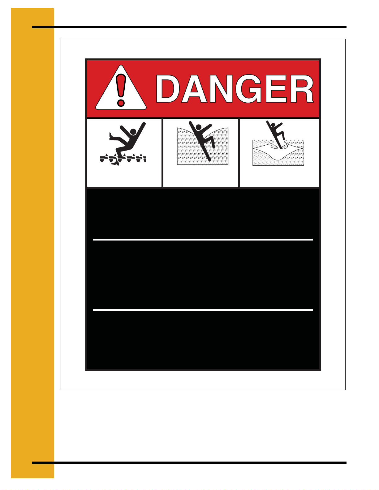
Chapter 2 Safety Decals ..................................................................................................................... 5
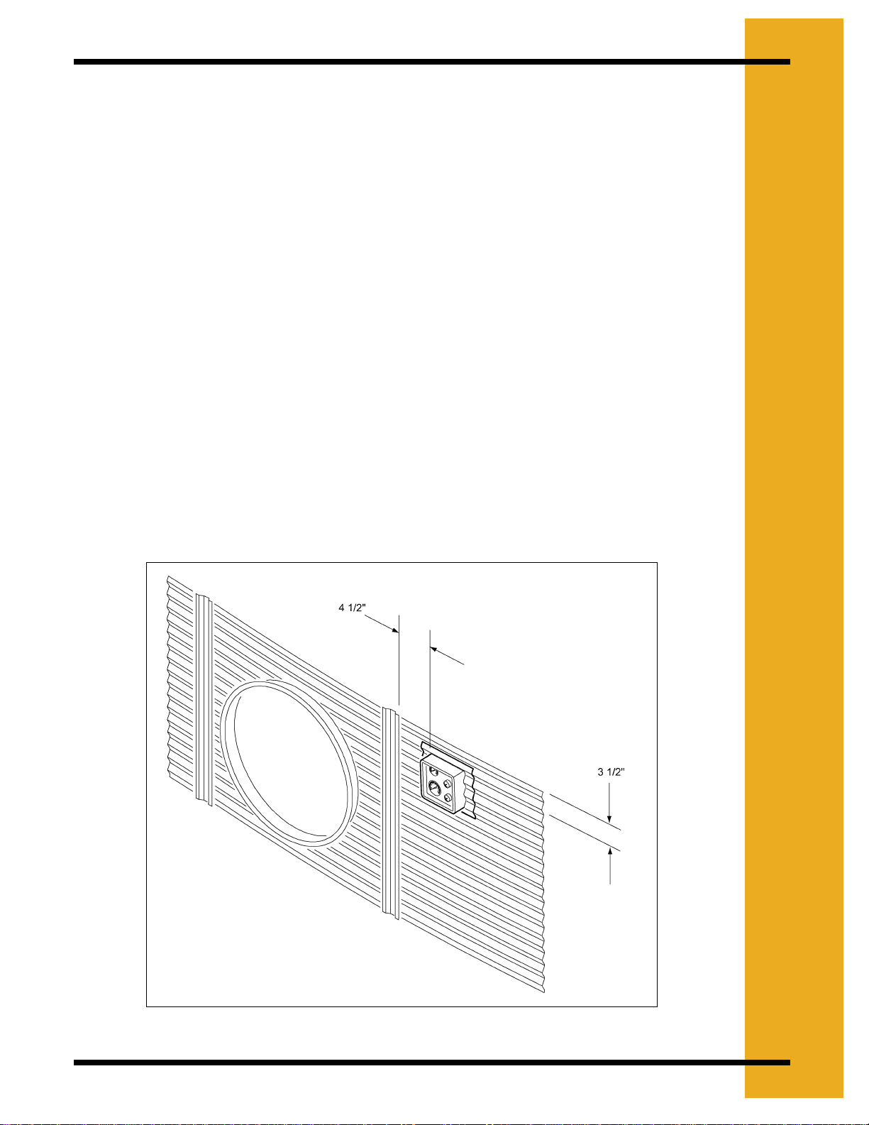
Chapter 3 General Installation ........................................................................................................... 7
Installation Instruction ......................................................................................................... 8
Chapter 4 Installation of Top Dry Hi-Lo Thermostat ........................................................................ 9
Installation of Hi-Lo Thermostat ..........................................................................................9
Installation Instructions ........................................................................................................ 9
Chapter 5 Operation .........................................................................................................................10
Temperature Control .........................................................................................................10
Humidity Control ................................................................................................................10
Chapter 6 Operation & Service ........................................................................................................12
Hi - Lo Temperature Control .............................................................................................12
Humidistat - Thermostat Service .......................................................................................12
Chapter 7 Thermostat Parts ............................................................................................................. 14
Humidistat-Thermostat Parts ............................................................................................14
Lo-Temp Humidistat-Thermostat Parts .............................................................................15
Hi-Lo Humidistat-Thermostat Parts ...................................................................................16
Chapter 8 Thermostat Wiring ........................................................................................................... 17
Humidistat-Thermostat Wiring ...........................................................................................17
Thermostat Wiring .............................................................................................................18
Humidistat Wiring ..............................................................................................................19
Humidistat-Thermostat ......................................................................................................20
Chapter 9 Mounting Template ..........................................................................................................21
Chapter 10 Warranty ......................................................................................................................... 23

4 PNEG-236 Humidistat-Thermostat
1. SAFETY FIRST
Roof Damage Warning and Disclaimer
Humidistat-Thermostat Operation
Thank you for choosing a GSI product. It is designed to give excellent performance and service
for many years.
The principal concern of The GSI Group, Inc. (“GSI”) is your safety and the safety of others
associated with grain handling equipment. This manual is written to help you understand safe
operating procedures, and some of the problems that may be encountered by the operator or
other personnel.
As owner and/or operator, it is your responsibility to know what requirements, hazards and
precautions exist, and to inform all personnel associated with the equipment, or who are in the
dryer area. Avoid any alterations to the equipment. Such alterations may produce a very
dangerous situation, where serious injury or death may occur.
Safety Alert Symbol
The symbol shown is used to call your attention to instructions concerning your personal safety.
Watch for this symbol; it points out important safety precautions. It means “ATTENTION”,
“WARNING”, “CAUTION”, and “DANGER”. Read the message andbe cautious to the possibility
of personal injury or death.
GSI DOES NOT WARRANT ANY ROOF DAMAGE
CAUSED BY EXCESSIVE VACUUM OR INTERNAL
PRESSURE FROM FANS OR OTHER AIR MOVING
SYSTEMS. ADEQUATE VENTILATION AND/OR
“MAKEUP AIR” DEVICES SHOULD BE PROVIDED
FOR ALL POWERED AIR HANDLING SYSTEMS. GSI
DOES NOT RECOMMEND THE USE OF DOWNWARD
FLOW SYSTEMS (SUCTION). SEVERE ROOF
DAMAGE CAN RESULT FROM ANY BLOCKAGE OF
AIR PASSAGES. RUNNING FANS DURING HIGH
HUMIDITY/COLD WEATHER CONDITIONS CAN
CAUSE AIR EXHAUST OR INTAKE PORTS TO
FREEZE.
WARNING! BE ALERT!
Personnel operating or working around electrical fans should read
this manual. This manual must be delivered with equipment to its
owner. Failure to read this manual and its safety instructions is a
misuse of the equipment.

PNEG-236 Humidistat-Thermostat 5
2.SAFETYDECALS
The GSI Group, Inc. recommends contacting your local power company, and having a
representative survey your installation so the wiring is compatible with their system, and
adequate power is supplied to your unit.
Safety decals should be read and understood by all people in the grain handling area. The
bottom right decal should be present on the inside bin door cover of the two ring door, 24"
porthole door cover and the roof manway cover.
If a decal is damaged or is missing contact:
The GSI Group, Inc.
1004 E. Illinois St.
Assumption, IL 62510
Ph: (217)-226-4421
A free replacement will be sent to you.
WARNING
Stay clear of rotating
blade. Blade could start
automatically. Can cause
serious injury. Disconnect
power before servicing.
DC-1225

6 PNEG-236 Humidistat-Thermostat
2. SAFETY DECALS
Rotating flighting will
kill or dismember
Flowing material will
trap and suffocate
Flowing material will
collapse andsuffocate.
Keep clear of all augers.
DO NOT ENTER this bin!
Failure to heed these
warnings will result in
serious injury or death.
If you must enter the bin:
1. Shut off and lock out all power.
2. Use a safety harness and safety line.
3. Satation another person of the bin.
4. Avoid the center of the bin.
5. Wear proper breathing equipment or respirator.
DC-GBC-1A

PNEG-236 Humidistat-Thermostat 7
3.GENERALINSTALLATION
Figure 3A

8 PNEG-236 Humidistat-Thermostat
3. GENERAL INSTALLATION
Installation Instruction
Standard electrical safety practices and codes should be used when installing the Humidistat-
Thermostat. Refer to the National Electric Code Standard Handbook by the National Fire
Protection Association. A qualified electrician should make all wiring installations.
1. The Humidistat-Thermostat should be mounted on the side of the bin wall between the
foundation and the drying floor. It should be installed approximately 24" from the right side
of the transition as shown.
2. Usethetemplate onPage21. Withthese instructions,drillonly theholes necessaryforyour
particular model.
Note: For humidistat to operate properly optional cutout must be used.
3. Caulk the top and sides of the plastic housing using roll caulking supplied with the unit. Do
not caulk the bottom side of housing so moisture can escape.
4. Carefully insert sensing probes through bin wall and secure housing to wall using self-
drilling screws provided. Be careful not to overtighten screws. Damage to housing could
result.
5. Make wiring connections to heater as shown in heater owners manual.
ALWAYS DISCONNECT AND LOCK OUT POWER
BEFORE WORKING ON OR AROUND HEATER.

PNEG-236 Humidistat-Thermostat 9
4.INSTALLATIONOFTOPDRYHI-LOTHERMOSTAT
Installation of Hi-Lo Thermostat
The Hi-Lo Thermostat is designed for use with the GSI Top Dry Crop Dryer units. It comes with
one thermostat which is adjustable and cycles the heater from high to low flame. The Hi-Lo
Thermostat also comes with a thermometer for monitoring the plenum temperature.
Installation Instructions
1. Locate the mounting position of the thermostat as shown in Figure 4A.
2.Use thetemplate on Page 21.With theseinstructions,drill onlythe holesnecessary foryour
particular model.
3. Apply rope caulk to sides and top of plastic housing. Leave bottom open to let moisture
escape.
4.Secure housing tosidewall usingself-drilling screws supplied.Be careful not toovertighten.
Overtightening may cause the housing to crack.
5. Connect the black and white wires to the terminals marked bin hi-limit (3rd and 4th terminal
bottom left hand terminal strip) on fan and heater safety circuit board.
6. Connect the green and red wires to the terminals marked cycle (8th and 6th terminal bottom
left hand terminal strip) on fan and heater safety circuit board.
Figure 4A

10 PNEG-236 Humidistat-Thermostat
5. OPERATION
Temperature Control
1. Turn the fan unit ON and let it run 3 to 5 minutes to equalize temperature under the bin.
2. Set bypass switch to the “HUMIDISTAT OFF” position. This setting allows the unit to run
based on temperature only.
3. Rotate the thermostat knob clockwise to the warmest position.
4. Open the gas valves to the heater, and turn the heater ON. Set heater gas pressure to a
moderately high setting (5 to 10 PSI).
5. Monitor the thermometer on the thermostat housing. When the thermometer comes up to
the desired temperature, slowly turn the thermostat knob counter-clock-wise until the
heater cycles OFF.
6. Ifthe unit doesnot reach the desiredtemperature, graduallyincreasethe gaspressureuntil
the temperature rises to the desired level.
7. Watch the unit run through several cycles and make any final adjustments.
Note: The unit should be on approximately 80% of the time. If not adjust gas pressure.
8. Significant changes in outside air temperature may require readjustment of gas pressure.
Humidity Control
1. Set bypass switch to the “HUMIDISTAT ON” position. This setting allows the unit to run
based on temperature and humidity.
2. Set the thermostat (Humidistat-Thermostat units only) to the maximum temperature
desired. This allows the thermostat to function as a highlimit control only. See the above
Temperature Control for setting the thermostat.
3. Set the humidistat to the desired relative humidity level you want to maintain under your
drying floor. The heater will cycle on above this relative humidity, and OFF when this level
is reached.
4. Use the equilibrium moisture chart be low as a guide for setting the humidistat.

PNEG-236 Humidistat-Thermostat 11
5. OPERATION
Equilibrium Moisture Chart (Shelled Corn)
Boxed area indicates safe moisture for normal winter storage of shelled corn at 15%.
Grain to be stored through the summer or long term, needs to be 1 to 3 points dryer.
Air
Temperature
(F)
Relative Humidity - Percentage
35 40 45 50 55 60 65 70 75 80 85 90 95 100
20° 11.2 11.7 12.7 13.7 14.5 15.1 16.2 17.1 18.0 19.6 21.2 23.5 25.8 29.1
30° 10.8 11.3 12.2 13.1 13.9 14.6 15.5 16.4 17.4 18.7 20.2 22.5 25.0 28.3
40° 10.5 11.0 11.7 12.5 13.3 14.0 14.8 15.5 16.6 17.8 19.4 21.5 24.2 27.5
50° 10.1 10.6 11.3 12.0 12.7 13.3 14.1 14.8 15.8 16.9 18.6 20.5 23.4 26.7
60° 9.7 10.2 10.9 11.6 12.1 12.7 13.4 14.2 15.0 16.0 17.8 19.5 22.6 25.9
70° 9.0 9.7 10.4 11.1 11.5 12.0 12.8 13.5 14.5 15.4 16.8 18.5 21.3 24.5
80° 8.3 9.1 9.8 10.5 10.8 11.2 12.1 13.0 13.9 14.8 15.8 17.4 20.0 22.8

12 PNEG-236 Humidistat-Thermostat
6. OPERATION & SERVICE
Hi - Lo Temperature Control
1. Turn fan unit ON and let it run 3 to 5 minutes to equalize temperature under the bin.
2. Rotate the thermostat knob clockwise to warmest position.
3. Open gas valves (including lo-fire valve) to the heater and turn the heater ON. Set heater
gas pressure to a moderately high setting (5 to 10 PSI).
4. Monitor the thermometer on the thermostat housing. When the thermostat comes up to
desired temperature, slowly turn the most at knob counter-clockwise until heater cycles to
lo-flame.
5. If the unit does not reach desiredtemperature, gradually increase the gas pressure until the
temperature rises to desired level.
6. Adjust the lo-fire valve so that the temperature drops until the unit cycles back to hi-flame.
7. Watch the unit run through several cycles and make any final adjustments.
Note: The unit should cycle approximately two times per minute. If not adjust gas
pressure.
8. Significant changes in outside air temperature may require readjustment of gas pressure.
Note: If temperature of lo-flame exceeds thermostat settings (above normal outside
temperatures) unit will cycle from lo-flame to OFF. (Top Dry units will shut down
completely).
Humidistat - Thermostat Service
GSIThermostats aredesigned andbuilt to withstandtheharshconditionsusually foundin drying
bins. A yearly preventative maintenance inspection may extend the life of your heating controls
many years.
ALWAYS DISCONNECT AND LOCK OUT POWER
BEFORE WORKING ON OR AROUND HEATER.

PNEG-236 Humidistat-Thermostat 13
6. OPERATION & SERVICE
1. Remove mounting screws from the thermostat housing and remove the housing from the
bin wall.
2. Carefully remove the back panel from the housing. (It may be necessary to cut caulking).
3. Blow out any dust or dirt that may have collected inside the housing.
4. Inspect the wiring for any loose connections, or rodent and insect damage.
5. Replace the back panel and caulk the corners to help seal the unit.
6. Reinstall the unit on the bin wall.
TheAirstream Humidistat-Thermostatis mounted onthelowerright side of thegrain bin's
transition. This allows for easy service and operation.

14 PNEG-236 Humidistat-Thermostat
7. THERMOSTAT PARTS
Humidistat-Thermostat Parts
Figure 7A
Ref. # Part # Description
1HF-1431 2.66" Plastic Housing
HF-1446 4.00" Plastic Housing
2 HF-1432 Thermostat
3 HF-1433 Humidistat
4 HF-1434 Static Pressure Gauge
5 HH-1435 220 Degree Thermometer
6 HH-1436 Screen Plug
7 HH-1970 Plastic Knob
8 HH-2089 Large Red Plastic Plug
9 HH-1442 Toggle Switch
10 HF-7108 Thermostat Cover
11 HH-7032 Rubber Grommet
12 HH-7029 Heat Shrink Tube 1/2"
13 HF-7110 Humidistat Cover

PNEG-236 Humidistat-Thermostat 15
7. THERMOSTAT PARTS
Lo-Temp Humidistat-Thermostat Parts
Figure 7B
Ref. # Part # Description
1HF-1431 2.66" Plastic Housing
HF-1446 4.00" Plastic Housing
2 HF-3974 Lo-Temp Thermostat
3 HF-1433 Humidistat
4 HF-1434 Static Pressure Gauge
5 HH-3973 140 Degree Thermometer
6 HH-1436 Screen Plug
7 HH-1970 Plastic Knob
8 HH-2089 Large Red Plastic Plug
9 HH-1442 Toggle Switch
10 HF-7108 Thermostat Cover
11 HH-7032 Rubber Grommet
12 HF-7110 Humidistat Cover

16 PNEG-236 Humidistat-Thermostat
7. THERMOSTAT PARTS
Hi-Lo Humidistat-Thermostat Parts
Figure 7C
Ref. # Part # Description
1HF-1431 2.66" Plastic Housing
HF-1446 4.00" Plastic Housing
2 HF-7028 Lo-Temp Thermostat
3 HF-1434 Static Pressure Gauge
4 HF-1435 220 Degree Thermometer
5 HH-1436 Screen Plug
6 HH-1970 Plastic Knob
7 HH-2089 Large Red Plastic Plug
8 HH-7029 Heat Shrink Tube 1/2"
9 HH-7108 Thermostat Cover
10 HF-7032 Rubber Grommet
11 HF-7110 Humidistat Cover

PNEG-236 Humidistat-Thermostat 17
8.THERMOSTATWIRING
Humidistat-Thermostat Wiring
Figure 8A
Connect to Heater as shown in
Heater Manual
Black
Black
Purple
Purple
White
Wire Nut
Red
HUMIDISTAT
THERMOSTAT
BYPASS SWITCH

18 PNEG-236 Humidistat-Thermostat
8. THERMOSTAT WIRING
Thermostat Wiring
Figure 8B

PNEG-236 Humidistat-Thermostat 19
8. THERMOSTAT WIRING
Humidistat Wiring
Figure 8C

20 PNEG-236 Humidistat-Thermostat
8. THERMOSTAT WIRING
Humidistat-Thermostat
Figure 8D
Other manuals for PNEG-236
1
Table of contents
Popular Humidistat manuals by other brands

Skuttle Indoor Air Quality Products
Skuttle Indoor Air Quality Products Compustat SEH-7100-000 Safety and installation instructions

Vemer
Vemer HUMI user manual

Siemens
Siemens POWERS 134-1861 Technical instructions

Honeywell
Honeywell H8908ASPST - Humidistat Control installation instructions

MS Electronics
MS Electronics E914 Product guide