Hafco Metalmaster GHD-45G User manual

GEAR HEAD DRILL
OPERATION MANUAL
Edition No : GHD45G001
Date of Issue : 10/2017
Model
GHD-45G

2
OPERATION MANUAL
NOTE:
In order to see the type and model of the machine, please see the
specication plate. Usually found on the back of the machine. See
example (Fig.1)
Fig.1
GEAR HEAD DRILL
MACHINE
GHD-45G
MODEL NO.
SERIAL NO.
DATE OF MANF.
NOTE:
This manual is only for your reference. Owing to the continuous improvement of the ma-
chine, changes may be made at any time without obligation or notice. Please ensure the local
voltage is the same as listed on the specication plate before operating this electric machine.
Distributed by
www.machineryhouse.co.nz
MACHINE DETAILS

OPTIMUM
MASCHINEN - GERMANY
Version 1.0.1 dated 2017-05-19Page 2 Translation of the original instructions
DH45GGB
Table of contents
1 Safety
1.1 Type plate .................................................................................................................................................5
1.2 Safety instructions (warning notes)...........................................................................................................6
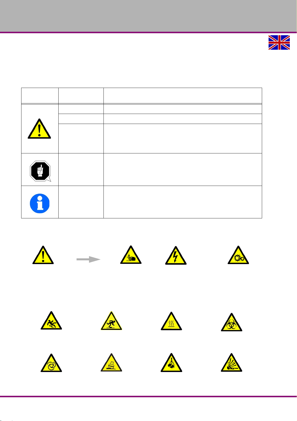
1.2.1 Classification of hazards ...............................................................................................................6
1.2.2 Other pictograms...........................................................................................................................6
1.3 Intended use .............................................................................................................................................7
1.4 Reasonably foreseeable misuse...............................................................................................................8
1.4.1 Avoiding misuse ............................................................................................................................8
1.5 Possible dangers caused by the geared drill ............................................................................................8
1.6 Qualification of personnel .........................................................................................................................9
1.6.1 Target group..................................................................................................................................9
1.6.2 Authorized persons .....................................................................................................................10
1.7 User positions .........................................................................................................................................10
1.8 Safety measures during operation..........................................................................................................11
1.9 Safety devices ........................................................................................................................................11
1.10 Safety check ...........................................................................................................................................11
1.11 Emergency-stop push button..................................................................................................................12
1.11.1 Main switch..................................................................................................................................12
1.11.2 Drill chuck guard..........................................................................................................................12
1.12 Personal protective equipment ...............................................................................................................13
1.13 Safety during operation...........................................................................................................................13
1.14 Safety during maintenance.....................................................................................................................14
1.14.1 Disconnecting and securing the geared drill ...............................................................................14
1.15 Using lifting equipment ...........................................................................................................................14
1.15.1 Mechanical maintenance.............................................................................................................14
1.16 Accident report........................................................................................................................................14
1.17 Electrical system.....................................................................................................................................14
1.18 Inspection deadlines...............................................................................................................................15
2 Technical specification
2.1 Emissions ...............................................................................................................................................17
2.2 Dimensions .............................................................................................................................................19
3 Delivery, internal transport, unpacking
3.1 Delivery...................................................................................................................................................20
3.2 Internal transport.....................................................................................................................................20
3.3 Unpacking...............................................................................................................................................21
3.4 Lifting the machine..................................................................................................................................21
3.5 Installation requirements.........................................................................................................................22
3.5.1 Foundation and ground ...............................................................................................................22
3.6 Fixing ......................................................................................................................................................22
3.6.1 Assembly drawing .......................................................................................................................23
3.7 Lubrication ..............................................................................................................................................23
3.7.1 Gear ............................................................................................................................................24
3.7.2 Coolant system............................................................................................................................24
3.8 First commissioning ................................................................................................................................24
3.9 Electrical connection...............................................................................................................................25
3.9.1 Connecting the optional foot switch.............................................................................................26
3.9.2 Warming up the machine ............................................................................................................26
4Operation
4.1 Control and indicating elements .............................................................................................................27
4.2 Control panel ..........................................................................................................................................28
4.2.1 Drill depth stop ............................................................................................................................28

OPTIMUM
MASCHINEN - GERMANY
Version 1.0.1 dated 2017-05-19 Page 3Translation of the original instructions
DH45G GB
4.3 Switching on the machine ...................................................................................................................... 28
4.4 Switching off the machine ...................................................................................................................... 29
4.4.1 Gear selector switch.................................................................................................................... 29
4.5 Spindle quill feed .................................................................................................................................... 29
4.5.1 Manual spindle sleeve feed......................................................................................................... 29
4.5.2 Automatic spindle sleeve feed .................................................................................................... 29
4.6 Disassembly, assembly of drill chucks and drill bits ............................................................................... 29
4.6.1 Use of the drill chuck................................................................................................................... 29
4.6.2 Disassembly with integrated drill drift.......................................................................................... 29
4.6.3 Fitting the drill chuck ................................................................................................................... 30
4.7 Coolant equipment ................................................................................................................................. 30
4.8 Footswitch - Rotation reversal................................................................................................................ 30
5 Determining the cutting speed and the speed
5.1 Table cutting speeds / infeed ................................................................................................................. 31
5.2 Speed table ............................................................................................................................................ 31
5.3 Examples to calculatory determine the required speed for your drilling machine .................................. 33
6 Maintenance
6.1 Safety ..................................................................................................................................................... 34
6.1.1 Preparation.................................................................................................................................. 34
6.1.2 Restarting.................................................................................................................................... 34
6.2 Inspection and maintenance .................................................................................................................. 35
6.3 Repair..................................................................................................................................................... 39
6.3.1 Customer service technician....................................................................................................... 39
6.4 Cooling lubricants and tanks .................................................................................................................. 40
6.4.1 Inspection plan for water-mixed cooling lubricants ..................................................................... 41
7 Malfunctions
8 Ersatzteile - Spare parts
8.1 Ersatzteilbestellung - Ordering spare parts ............................................................................................ 45
8.2 Elektrische Ersatzteile - Electrical spare parts ....................................................................................... 45
8.3 Schaltplan - Wiring diagram ................................................................................................................... 45
8.4 DH45G ................................................................................................................................................... 46
8.5 Schaltplan - Wiring diagram 1-4 ............................................................................................................. 56
8.6 Schaltplan - Wiring diagram 2-4 ............................................................................................................. 57
8.7 Schaltplan - Wiring diagram 3-4 ............................................................................................................. 58
8.8 Schaltplan - Wiring diagram 4-4 ............................................................................................................. 59
9 Appendix
9.1 Copyright ................................................................................................................................................ 63
9.2 Terminology/Glossary ............................................................................................................................ 63
9.2.1 Change information operating manual........................................................................................63
9.3 Liability claims/warranty ......................................................................................................................... 64
9.4 Storage................................................................................................................................................... 65
9.5 Advice for disposal / Options of reuse:................................................................................................... 65
9.5.1 Decommissioning........................................................................................................................ 66
9.5.2 Disposal of new device packaging .............................................................................................. 66
9.5.3 Disposal of the old device ........................................................................................................... 66
9.5.4 Disposal of electrical and electronic components ....................................................................... 66
9.5.5 Disposal of lubricants and coolants............................................................................................. 67
9.6 Disposal via municipal collection facilities .............................................................................................. 67
9.7 RoHS, 2011/65/EU................................................................................................................................. 67
9.8 Product follow-up.................................................................................................................................... 67

OPTIMUM
MASCHINEN - GERMANY
Version 1.0.1 dated 2017-05-19Page 4 Translation of the original instructions
DH45GGB
DH45G_GB_preface.fm
Preface
Dear customer,
Thank you very much for purchasing a product made by OPTIMUM.
OPTIMUM metal working machines offer a maximum of quality, technically optimum solutions and convince
by an outstanding price performance ratio. Continuous enhancements and product innovations guarantee
state-of-the-art products and safety at any time.
Before commissioning the machine please thoroughly read these operating instructions and get familiar with
the machine. Please also make sure that all persons operating the machine have read and understood the
operating instructions beforehand.
Keep these operating instructions in a safe place nearby the machine.
Information
The operating instructions include indications for safety-relevant and proper installation, operation and main-
tenance of the machine. The continuous observance of all notes included in this manual guarantee the safety
of persons and of the machine.
The manual determines the intended use of the machine and includes all necessary information for its eco-
nomic operation as well as its long service life.
In the paragraph "Maintenance" all maintenance works and functional tests are described which the operator
must perform in regular intervals.
The illustration and information included in the present manual can possibly deviate from the current state of
construction of your machine. Being the manufacturer we are continuously seeking for improvements and
renewal of the products. Therefore, changes might be performed without prior notice. The illustrations of the
machine may be different from the illustrations in these instructions with regard to a few details. However,
this does not have any influence on the operability of the machine.
Therefore, no claims may be derived from the indications and descriptions. Changes and errors are reserved
!
Your suggestion with regard to these operating instructions are an important contribution to optimising our
work which we offer to our customers. For any questions or suggestions for improvement, please do not hesi-
tate to contact our service department.
If you have any further questions after reading these operating instructions and you are not able to
solve your problem with a help of these operating instructions, please contact your specialised
dealer or directly the company OPTIMUM.
Optimum Maschinen Germany GmbH
Dr.- Robert - Pfleger - Str. 26
D-96103 Hallstadt
Fax (+49)0951 / 96 555 - 888
Email: in[email protected]
Internet: www.optimum-maschinen.de

OPTIMUM
MASCHINEN - GERMANY
Safety
Version 1.0.1 dated 2017-05-19 Page 5Translation of the original instructions
DH45G GB
DH45G_GB_1.fm
1 Safety
Glossary of symbols
This part of the operating instructions
explains the meaning and use of the warning notes included in these operating instructions,
defines the intended use of the geared drill,
points out the dangers that might arise for you or others if these instructions are not
observed,
informs you about how to avoid dangers.
In addition to these operation instructions, please observe
the applicable laws and regulations,
the statutory provisions for accident prevention,
the prohibition, warning and mandatory signs as well as the warning notes on the geared
drill.
Always keep this documentation close to the geared drill.
1.1 Type plate
INFORMATION
If you are unable to rectify an issue using these operating instructions, please contact us for
advice:
Optimum Maschinen Germany GmbH
Dr. Robert-Pfleger-Str. 26
D-96103 Hallstadt, Germany
Email: info@optimum-maschinen.de
provides further instructions
calls on you to act
listings

OPTIMUM
MASCHINEN - GERMANY
Safety
Version 1.0.1 dated 2017-05-19Page 6 Translation of the original instructions
DH45GGB
DH45G_GB_1.fm
1.2 Safety instructions (warning notes)
1.2.1 Classification of hazards
We classify the safety warnings into different categories. The table below gives an overview of
the classification of symbols (ideogram) and the warning signs for each specific danger and its
(possible) consequences.
1.2.2 Other pictograms
Symbol Alarm expres-
sion Definition / consequence
DANGER! Impending danger that will cause serious injury or death to people.
WARNING! A danger that can cause serious injury or death.
CAUTION!
A danger or unsafe procedure that can cause personal injury or damage to
property.
ATTENTION!
Situation that could cause damage to the geared drill and product, as well as
other types of damage.
No risk of injury to persons.
Information
Practical tips and other important or useful information and notes.
No dangerous or harmful consequences for people or objects.
In case of specific dangers, we replace the pictogram with
or
general danger with a warning of injury to hands, hazardous
electrical voltage,
rotating parts.
Warning: danger of
slipping!
Warning: risk of stumbling! Warning: hot surface! Warning: biological hazard!
Warning: automatic start-
up!
Warning: tilting danger! Warning: suspended loads! Caution, danger of
explosive substances!

OPTIMUM
MASCHINEN - GERMANY
Safety
Version 1.0.1 dated 2017-05-19 Page 7Translation of the original instructions
DH45G GB
DH45G_GB_1.fm
1.3 Intended use
WARNING!
In the event of improper use of the geared drill
will endanger personnel,
will endanger the machine and other material property of the operating company,
the correct function of the geared drill may be affected.
The geared drill is designed and manufactured to be used in a non-explosive environment. The
geared drill is designed and manufactured for holes in cold metals or other non flammable
materials or that not constitute a health hazard using a rotating filing-stripping tool that has a
number of grooves for collecting the filings.
If the geared drill is used in any way other than described above, modified without authoriza-
tion of Optimum Maschinen Germany GmbH, then the geared drill is being used improperly.
We will not be held liable for any damages resulting from any operation which is not in accord-
ance with the intended use.
We expressly point out that the guarantee or CE conformity will expire due to any constructive
technical or procedural changes which had not been performed by the company Optimum
Maschinen Germany GmbH.
It is also part of intended use that
observe the limits of the geared drill,
the operating manual is observed,
the inspection and maintenance instructions are observed.
"Technical specification“ on page 16
WARNING!
Extremely severe injuries.
It is forbidden to make any modifications or alternations to the operation values of the
geared drill! They could endanger the personnel and cause damage to the geared drill.
Switching on forbidden! Do not climb onto the
machine!
Read the operating
instructions before
commissioning!
Pull out the mains plug!
Wear protective glasses! Wear protective gloves! Wear safety shoes! Wear a protective suit!
Use ear protection! Only switch during
standstill!
Protect the environment! Contact address

OPTIMUM
MASCHINEN - GERMANY
Safety
Version 1.0.1 dated 2017-05-19Page 8 Translation of the original instructions
DH45GGB
DH45G_GB_1.fm
1.4 Reasonably foreseeable misuse
Any use other than that specified under "Intended use" or any use beyond that described will be
deemed non-intended use and is not permissible.
Any other use must be discussed with the manufacturer.
It is only allowed to process metal, cold and non-inflammable materials with the geared drill.
In order to avoid misuse, it is necessary to read and understand the operating instructions
before first commissioning.
Operators must be qualified.
1.4.1 Avoiding misuse
Use of suitable cutting tools.
Adapting the speed adjustment and feed to the material and workpiece.
Clamp workpieces firmly and free of vibration.
ATTENTION!
The workpiece is always to be fixed by a machine vice, jaw chuck or by another
appropriate clamping tool such as for the clamping claws.
WARNING!
Risk of injury caused by flying workpieces.
Clamp the workpiece in the machine vice. Make sure that the workpiece is firmly clamped in the
machine vice and that the machine vice is firmly clamped onto the machine table.
Use cooling and lubricating agents to increase the durability of the tool and to improve the
surface quality.
Clamp the cutting tools and workpieces on clean clamping surfaces.
Sufficiently lubricate the machine.
Set the bearing clearance and guides correctly.
Recommendations:
Insert the drill in a way that it is exactly positioned between the three clamping jaws of the
quick action chuck.
When drilling, make sure that
the suitable speed is set depending on the diameter of the drill,
the pressure must only be such that the drill can cut without load,
if there is too much pressure, the drill will wear quickly and may even break or jam in the
borehole. If the drill jams, immediately stop the main motor by pressing the emergency stop
switch,
use commercial cooling/lubricating agents for hard materials, e.g. steel and
generally always back the spindle out of the workpiece while it is still turning.
1.5 Possible dangers caused by the geared drill
The geared drill was built using state-of-the-art technology.
Nevertheless, there is a residual risk as the geared drill operates with
at high speeds,
with rotating parts,
electrical voltage and currents.
We have used design and safety engineering to minimize the health risk to personnel resulting
from these hazards.

OPTIMUM
MASCHINEN - GERMANY
Safety
Version 1.0.1 dated 2017-05-19 Page 9Translation of the original instructions
DH45G GB
DH45G_GB_1.fm
If the geared drill is used and maintained by personnel who are not duly qualified, there may be
a risk resulting from incorrect or unsuitable maintenance of the geared drill.
INFORMATION
Everyone involved in the assembly, commissioning, operation and maintenance must
be duly qualified,
and strictly follow these operating instructions.
In the event of improper use
there may be a risk to personnel,
there may be a risk to the machine and other material values,
the correct function of the geared drill may be affected.
Always disconnect the geared drill if cleaning or maintenance work is being carried out, or is no
longer in use.
WARNING!
The geared drill may only be operated with functional safety devices.
Disconnect the geared drill immediately, whenever you detect a failure in the safety
devices or when they are not fitted!
All additional devices installed by the operator must be equipped with the stipulated
safety devices. This is your responsibility as the operator!
"Safety devices“ on page 11
1.6 Qualification of personnel
1.6.1 Target group
This manual is addressed to
the operating companies,
the operators,
the maintenance personnel.
Therefore, the warning notes refer to both, operation and maintenance personnel of the geared
drill.
Determine clearly and explicitly who will be responsible for the different activities on the geared
drill (operation, setting up, maintenance and repair).
Unclear responsibilities constitute a safety risk!
Always disconnect plug of the geared drill from the electrical power supply. This will prevent it
from being used by unauthorized persons.
The qualifications of the personnel for the different tasks are mentioned below:
Operator
The operator is instructed by the operating company about the assigned tasks and possible
risks in case of improper behaviour. The operator may only carry out tasks that exceed normal
operation if this is stated in these instructions and the operating company has explicitly
entrusted him with the task.
Qualified electrician
With professional training, knowledge and experience as well as knowledge of respective
standards and regulations, qualified electricians are able to perform work on the electrical sys-
tem and recognise and avoid any possible dangers.
Qualified electricians have been specially trained for the working environment, in which they are
working and know the relevant standards and regulations.

OPTIMUM
MASCHINEN - GERMANY
Safety
Version 1.0.1 dated 2017-05-19Page 10 Translation of the original instructions
DH45GGB
DH45G_GB_1.fm
Qualified personnel
Due to their professional training, knowledge and experience as well as knowledge of relevant
regulations, qualified personnel are able to perform the assigned tasks and to independently
recognise and avoid any possible dangers.
Instructed person
Instructed persons were instructed by the operating company regarding the assigned tasks and
any possible risks of improper behaviour.
1.6.2 Authorized persons
WARNING!
Inappropriate operation and maintenance of the geared drill constitutes a danger for the
personnel, objects and the environment.
Only authorized personnel may operate the geared drill !
Authorized operating and maintenance personnel are specialists instructed and trained by the
operator company and the manufacturer.
Obligations of the operating company
train the personnel,
instruct the personnel in regular intervals (at least once a year) on
- all safety regulations relevant to the machine,
- its operation and
- generally accepted engineering standards.
check the personnel‘s knowledge level,
document the training/instruction,
have attendance at the training/instruction confirmed by signature and
check whether the personnel is working in a safety and risk-conscious manner and follow-
ing the operating instructions.
define and document the inspection deadlines for the machine in accordance with § 3 of the
Factory Safety Act and perform an operational risk analysis in accordance with § 6 of the
Work Safety Act.
Obligations of the operator
have obtained a training regarding the handling of the geared drill,
know the function and mode of action,
before taking the machine in operation
- have read and understood the operating manual,
- be familiar with all safety devices and instructions.
Additional
requirements
regarding the
qualification
Additional requirements apply for work on the following machine components:
Electrical parts or operating agents: shall only be performed by an electrician or under the
guidance and supervision of an electrician.
Before starting work on electrical parts or operating agents, the following actions must be
taken in the order given:
disconnect all poles,
secure against restarting,
check that there is no voltage.
1.7 User positions
The operator position is in front of the geared drill.

OPTIMUM
MASCHINEN - GERMANY
Safety
Version 1.0.1 dated 2017-05-19 Page 11Translation of the original instructions
DH45G GB
DH45G_GB_1.fm
1.8 Safety measures during operation
CAUTION!
Danger due to inhaling dust and mist that are hazardous to health.
Depending on the materials to be machined and the agents used, dusts and mists can
arise that are detrimental to health.
Ensure that the harmful dust and mist generated are safely sucked off at the point of
origin and routed away from the working area or filtered. To do so, use a suitable
extraction unit.
CAUTION!
Risk of fire and explosion by using flammable materials or cooling lubricants.
Extra precautionary measures must be taken before machining flammable materials (e.g.
aluminium, magnesium) or using combustible agents (e.g. spirit) to avert a health
hazard.
1.9 Safety devices
Use the geared drill only with properly functioning safety devices.
Stop the geared drill immediately, if a safety device fails or is faulty or becomes ineffective.
It is your responsibility!
If a safety device has been activated or has failed, the geared drill must only be used if you
the cause of the fault has been eliminated,
you have verified that there is no danger to personnel or objects.
WARNING!
If you bypass, remove or deactivate a safety device in any other way, you are
endangering yourself and other personnel working with the geared drill. The possible
consequences are
injuries due to components or workpieces flying off at high speed,
contact with rotating parts,
fatal electrocution,
The geared drill includes the following safety devices:
an emergency stop push button,
a drilling table with T-slots to fix the workpiece or a vice,
a drill chuck guard, in order to prevent interference with the rotating tool.
INFORMATION
The geared drill can only be switched on if the drill chuck guard is closed.
WARNING!
Although the isolating safety devices provided and delivered with the machine are
designed to reduce the risks of workpieces being ejected or parts of tools or workpieces
breaking off, they cannot eliminate these risks completely. Always work carefully and
observe the limits of the machining process.
1.10 Safety check
Check the geared drill before each start-up or at least once per shift. Inform the person respon-
sible immediately of any damage, defects or changes in the operating function.
Check all safety devices
at the beginning of each shift (with the machine stopped),
once a week (with the machine in operation) and

OPTIMUM
MASCHINEN - GERMANY
Safety
Version 1.0.1 dated 2017-05-19Page 12 Translation of the original instructions
DH45GGB
DH45G_GB_1.fm
after all maintenance and repair work.
Check that prohibition, warning and information signs and the labels on the geared drill
are legible (clean them, if necessary)
are complete (replace if necessary).
INFORMATION
Organise the checks according to the following table;
1.11 Emergency-stop push button
ATTENTION!
The drilling spindle keeps turning for a short time even after actuating the emergency
stop push button depending on the preset speed.
1.11.1 Main switch
In the "0" position, the lockable main switch can be secured against accidental or non-author-
ised switching on by means of a padlock.
The power supply is interrupted by switching off the main plug.
Except for the areas marked by the pictogram in the margin. In these areas there might be volt-
age, even if the main switch is switched-off.
WARNING!
Dangerous voltage even if the main switch is switched off.
The areas marked by the pictogram might contain live parts, even if the main switch is switched
off.
1.11.2 Drill chuck guard
Adjust the guard to the correct height before you start working.
To do so, slacken the clamping screw, set the required height and re-tighten the clamping
screw.
General check
Equipment Check OK
Guards Mounted, firmly bolted and not damaged
Signs,
Markers
Installed and legible
Date: Checked by (signature):
Functional check
Equipment Check OK
Emergency-stop push
button
After actuating the emergency stop push button the geared
drill must be switched off.
Drill chuck guard The geared drill can only be switched on if the drill chuck
guard is closed. The engine must switch off when the drill
chuck guard is opened during operation.
Date: Checked by (signature):

OPTIMUM
MASCHINEN - GERMANY
Safety
Version 1.0.1 dated 2017-05-19 Page 13Translation of the original instructions
DH45G GB
DH45G_GB_1.fm
There is a switch integrated in the spindle protection mounting which monitors the closed posi-
tion.
INFORMATION
The machine cannot be started, if the drill chuck guard is not closed.
1.12 Personal protective equipment
For some works you need personnel protective equipment as protective equipment. These are
Safety helmet,
protective glasses or face guard,
protective gloves,
safety shoes with steel toe caps,
ear protection.
Before starting work make sure that the required personnel protective equipment is available at
the work place.
CAUTION!
Dirty or contaminated personnel protective equipment can cause illness.
Clean your personal protective equipment
after each use,
regularly once a week.
Personal protective equipment for special works
Protect your face and your eyes: Wear a safety helmet with facial protection when performing
work where your face and eyes are exposed to hazards.
Wear protective gloves when handling pieces with sharp edges.
Wear safety shoes when you assemble, disassemble or transport heavy components.
1.13 Safety during operation
We provide information about the specific dangers when working with and on the geared drill in
the descriptions for these types of work.
WARNING!
Before switching on the geared drill make sure that there are
no dangers generated for persons,
no objects are damaged.
Avoid any unsafe work methods:
Make sure that your operation does not create a safety hazard.
The rules specified in these operating instructions must be observed during assembly,
operation, maintenance and repair.
Do not work on the geared drill if your concentration is reduced, for example, because you
are taking medication.
Observe the accident prevention regulations issued by your Employers Liability Insurance
Association or other supervisory authorities applicable to your company.
Inform the supervisor about all hazards or faults.
Stay on the geared drill until the machine completely stopped moving.
Use the specified personal protective equipment. Ensure you wear close-fitting clothing
and, if necessary, a hairnet.
Do not use protective gloves when drilling.

OPTIMUM
MASCHINEN - GERMANY
Safety
Version 1.0.1 dated 2017-05-19Page 14 Translation of the original instructions
DH45GGB
DH45G_GB_1.fm
1.14 Safety during maintenance
Inform the operators in good time of any maintenance and repair works.
Report all safety relevant changes and performance details of the geared drill or their opera-
tional behavior. Any changes must be documented, the operating instructions updated and
machine operators instructed accordingly.
1.14.1 Disconnecting and securing the geared drill
Switch off the geared drill with the main switch and secure the main switch with a padlock
against unauthorised switching-on or switching-on by accident.
All machine parts as well as all dangerous voltages are switched off. Excepted are only the
positions which are marked with the adjoining pictogram.
1.15 Using lifting equipment
WARNING!
The use of unstable lifting and load suspension equipment that might break under load
can cause severe injuries or even death.
Check that the lifting and load suspension gear
they have sufficient load carrying,
and that it is in perfect condition.
Observe the accident prevention regulations issued by your Employers Liability
Insurance Association or other supervisory authorities applicable to your company.
Fasten the loads properly. Never walk under suspended loads!
1.15.1 Mechanical maintenance
Reinstall all protection and safety devices after any maintenance work once the work has been
completed.This includes:
covers,
safety instructions and warning signs,
grounding cables.
Check if they are working properly!
1.16 Accident report
Inform your supervisors and Optimum Maschinen Germany GmbH immediately in the event of
accidents, possible sources of danger and any actions which almost led to an accident (near
misses).
There are many possible causes for "near misses".
The sooner they are notified, the quicker the causes can be eliminated.
1.17 Electrical system
Have the machine and/or the electric equipment checked regularly. Immediately eliminate all
defects such as loose connections, defective wires, etc.
A second person must be present during work on live components to disconnect the power in
the event of an emergency. Disconnect the machine immediately if there is a malfunction in the
power supply!
Comply with the required inspection intervals in accordance with the factory safety directive,
operating equipment inspection.
The operator of the machine must ensure that the electrical systems and operating equipment
are inspected with regards to their proper condition, namely,

OPTIMUM
MASCHINEN - GERMANY
Safety
Version 1.0.1 dated 2017-05-19 Page 15Translation of the original instructions
DH45G GB
DH45G_GB_1.fm
by a qualified electrician or under the supervision and direction of a qualified electrician,
prior to initial commissioning and after modifications or repairs, prior to recommissioning
and at certain intervals.
The deadlines must be set so that arising, foreseeable defects can be detected in a timely man-
ner.
The relevant electro-technical rules must be followed during the inspection.
The inspection prior to initial commissioning is not required if the operator receives confirma-
tion from the manufacturer or installer that the electrical systems and operating equipment com-
ply with the accident prevention regulations, see conformity declaration.
Permanently installed electrical systems and operating equipment are considered constantly
monitored if they are continually serviced by qualified electricians and inspected by means of
measurements in the scope of operation (e.g. monitoring the insulation resistance).
1.18 Inspection deadlines
Define and document the inspection deadlines for the machine in accordance with § 3 of the
Factory Safety Act and perform an operational risk analysis in accordance with § 6 of the Work
Safety Act. Also use the inspection intervals in the maintenance section as reference values.

OPTIMUM
MASCHINEN - GERMANY
Technical specification
Version 1.0.1 dated 2017-05-19Page 16 Translation of the original instructions
DH45GGB
DH45G_GB_2.fm
2 Technical specification
The following information represents the dimensions and indications of weight and the manu-
facturer‘s approved machine data.
DH45G
Electrical connection 400 V / 3 Ph ~50 Hz
Spindle drive motor power 2.2 kW
Coolant pump motor power 40W
Drilling capacity in steel (S235JR) [mm] Ø45
Tapping in steel (S235JR) [mm] M 35
350 mm
180 mm
Spindle seat MT4
Table size
Length x Width of the working surface 530 x 530 mm
Bearing load drilling table [kg] 250
Tilting the table to the side 0 - 90°
Drilling table rotate 360°
T-slot size / distance / number
18mm / 125 mm / 3
Distance spindle - table [mm] 70 - 730 mm
Maximum distance [mm]
spindle - stand 1210
Throat depth
Spindle stroke
T-slot size

OPTIMUM
MASCHINEN - GERMANY
Technical specification
Version 1.0.1 dated 2017-05-19 Page 17Translation of the original instructions
DH45G GB
DH45G_GB_2.fm
2.1 Emissions
The airborne noise of the geared drill is 75 to 80 dB (A) at the operator position and operating
conditions in accordance with DIN ISO 8525
If the geared drill is installed in an area where various machines are in operation, the noise
exposure (immission) on the operator of the geared drill at the working place may exceed 80
dB(A).
INFORMATION
This numerical value was measured on a new machine under the operating conditions specified
by the manufacturer. The noise behaviour of the machine might change depending on the age
and wear of the machine.
Furthermore, the noise emission also depends on production engineering factors, e.g. speed,
material and clamping conditions.
INFORMATION
The specified numerical value represents the emission level and does not necessarily a safe
working level.
Though there is a dependency between the degree of the noise emission and the degree of the
noise disturbance it is not possible to use it reliably to determine if further precaution measures
are required or not.
The following factors influence the actual degree of the noise exposure of the operator:
Characteristics of the working area, e.g. size of damping behaviour,
other noise sources, e.g. the number of machines,
other processes taking place in proximity and the period of time, during which the operator
Working surface stand [mm]
Length x Width of the working surface 755 x 480
Dimensions of the machine "Dimensions“ on page 19
Required space Keep a work area of at least one metre around the machine free for
operation and maintenance.
Machine weight [ kg ] 560
Gross weight (Packing + accessory) [ kg ] 670
Packing dimension L x B x H 2440 x 770 x 1110
Spindle speeds [ rpm ] 90 - 1520 rpm
Number of stages 8
Column diameter [mm] Ø 150 mm
Environmental conditions temperature 5 - 35 °C
Environmental conditions
Relative humidity 25-80%
Gear operating material 3 liters Mobilgear 629 "Schmierstoffe“ on page 61
Operating material
Toothed rod and drill column acid-free oil
Coolant equipment max. 5 liters "Schmierstoffe“ on page 61
DH45G

OPTIMUM
MASCHINEN - GERMANY
Technical specification
Version 1.0.1 dated 2017-05-19Page 18 Translation of the original instructions
DH45GGB
DH45G_GB_2.fm
is exposed to the noise.
Furthermore, it is possible that the admissible exposure level might be different from country to
country due to national regulations.
This information about the noise emission should, however, allow the operator of the machine
to more easily evaluate the hazards and risks.
CAUTION!
Depending on the overall noise exposure and the basic threshold values, machine
operators must wear appropriate hearing protection.
We generally recommend the use of noise and ear protection.

OPTIMUM
MASCHINEN - GERMANY
Technical specification
Version 1.0.1 dated 2017-05-19 Page 19Translation of the original instructions
DH45G GB
DH45G_GB_2.fm
2.2 Dimensions
A-A
AA
880
2445
595
350
150
615
530
190150270
445
480
18
435
755
530
Schwerpunkt / Ceentre of gravity
1545
450
Table of contents
Other Hafco Metalmaster Drill manuals

Hafco Metalmaster
Hafco Metalmaster GHD-38B User manual

Hafco Metalmaster
Hafco Metalmaster PD-440 User manual

Hafco Metalmaster
Hafco Metalmaster RAD-900 User manual

Hafco Metalmaster
Hafco Metalmaster HM-53GV User manual

Hafco Metalmaster
Hafco Metalmaster HM-46B User manual

Hafco Metalmaster
Hafco Metalmaster GHD-38A User manual