Hafco Metalmaster HM-53GV User manual

0
DRILLING&MILLING MACHINE
OPERATION MANUAL
SERIES

1
CONTENT
1. WARNING
2. USAGE
3. USE AND MAINTENACE
4. MAIN PARAMETERS
5. THE SYSTEM OF TRANSMITION AND
CHANGED SPEED
6. THE LUBRICATION OF MACHINE AND
ROLLING BEARING
7. ELECTRIC SYSTEM
8. TRANSPORTAND ATTENTION
9. SIMPLE MALFUNCTION&OBVIATION
10. PARTS DIVISION AND PARTS LIST
11.HEAD GERA (STEP-LESS) EXPLOSION
DIAGRAM

2
WARNING
1. Read and understand the entire instruction manual before operating the machine.
2. Always be sure to wear safe goggles and wear safety shoes during operation
3. Make certain the machine is properly grounded.
4. Before operating the machine, remove tie, rings, watches, other jewelry, and roll
up sleeves above the elbows. Remove all loose clothing and confine long hair. Do
NOT wear gloves.
5. Keep the floor around the machine clean and free of scrap material, oil and
grease.
6. Keep machine guards in place at all times when the machine is in use. If removed
for maintenance purposes, use extreme caution and replace the guards
immediately.
7. Do NOT over reach. Maintain a balanced stance at all times so that you do not fall
or lean against blades or other moving parts.
8. Make all machine adjustments or maintenance with the machine unplugged from
the power source.
9. Use the right tool. Do not force a tool or attachment to do a job which it was not
designed for.
10. Make certain the motor switch is in the OFF position before connecting the
machine to power supply.
11. Keep visitors a safe distance from the work area.

3
12. Never attempt any operation or adjustment if the procedure is not understood.
13. Keep fingers away from revolving parts and cutting tools while operating.
14. Do not attempt to adjust or remove tools during operation.
15. Always keep cutters sharp.
16. Keep away from the turning handwheel, especially high speed.
17. Must pour the machine oil into the gear box and the power feed (optional) rightly.
18. Failure to comply with all of these warnings may cause serious injury.
1. Attention
1.1 inspection and acceptance
Please check carefully when open the package and make sure no parts are missing.
1.2 safety
Please read the operation manual carefully before the installation and adjustment of
the machine. When finish the installation, check all the details and trial run the
machine idlly before put it into operation.
1.3 caution
Keep in mind the safety measures for electrical and operating protection.
2. Work environment
2.1 the elevation of workshop has to be 2000rpm or less.
2.2 no conductive dust allowed.
2.3 no explosive factor allowed.
2.4 no corrosive gas or steam which may corrode metal or damage the insulation.
2.5 keep away from the source of impact or vibration.
3. Operation instruction

4
3.1.1 Before starting the machine, read carefully the operation manual and be fully
acquainted with all the details.
3.1.2 The operator should be familiar with all the rules and points of attention of
running and maintaining the machine.
3.1.3 Remove all the anti-rust coating or grease from the machine.
3.1.4 There's a reliable ground protection the ground wire must be connected
properly before it in operation.
4. Lubrication
Lubricate the sliding and rotating part before trial run.
Pour No.40 machine oil into the gear box and the power feed (optional). Till
indicating through the oil level indicators then do a overall check.
Keep oil level above the mark.

5

6
Ⅰ
USAGE
The machine is used for cutting metals and nonmetals. It's suitable to drill, mill
and widely use in the field for instrument, machining, repairing for cutting a single
part or a batch of parts.
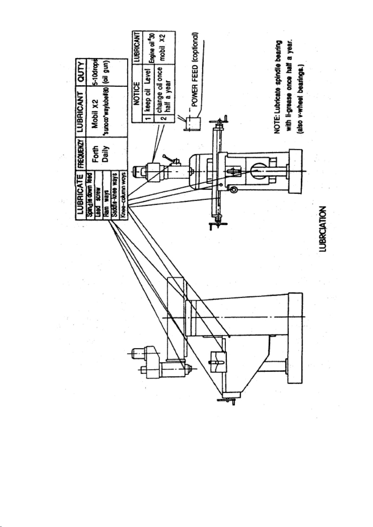
II USE AND MAINTENANCE
(Refer to chartg 1.)
1. The user must read the operation manual carefully, know structure and ability
of every handle, the system of transmission and lubrication well.
2. Before operating, inspect the normal conditions of the column lock handle, the
spindle sleeve and electric equipments. The ground line must be connect in the
ground.
3. When the position of spindle box to the working table need to be adjusted,
two clamping shaft ①locating on the right side of hoist--de-scend sliding must be
lossed firstly, then turn the hoist--descend handle in front of machine, to hoist or
descend the working table to the idea position, finally clamp the clamping shaft ①.
4. A micro--feeding institute is applied to the machine, before using, pls turn
locking bolt ③in right side to form the handle body with micro-feeding can be
realized. The spindle can revolve for tapping, through the universal switch equipped
on the left side of the head.
But if the power motor is single phase, such function can't be realized.
5. The handle body must be separated from micro-gear during drilling, when
drilling finished, loosen the handle ⑤, the sleeve will reset automatically. The elastic
force can be adjusted after loosing the screw locating in the bottom of spindle box

7
and turning the spring to different position. The spindle sleeve clamping handle ⑥
should be clamped for milling. To obtain the best effect, pls choose the 3-blade
vertical milling tool, the most, the working table must be hoisted to the nearest
position to the spindle when the 2-blade milling tool is used.
6. The boring function can be realized after equipping relative accessories. It is
better to apply to micro-feeding during milling and boring.
7. The spindle box can turn ±90°in vertical plane for turning the spindle box,
pls firstly loosen the three tighting nut connecting with spindle box, turn the spindle
to the needed angle through turning micro-worm ⑧, finally pls tight the nut.
8. The cross-slide of spindle box can be realized through the ram moving for
cross-sliding, pls firstly loosen the two clamping bolts ⑨locating on the right side of
the ram, turn the gear shaft ⑩, to move the ram and spindle box, and tight the two
clamping bolts.
9. The spindle box can turn 360°around the column in the horizontal plane. To
realize this, pls firstly loosen the 4 pcs of clamping nuts ⑾under the ram, turn the
ram to the suitable position, finally tight the 4 pcs of clamping nuts.
10. The spindle's turn and revolve can be realized by the switch located in the
right side of hoist-descend sliding.
11. The horizontal milling can be realized by turn the vertical spindle box 90°.
The spindle box must turn 180°when the tool shaft and jack applied for assistance.
12. If the machine doesn't work well or have irregular noise, pls immediately shut
off machine.

8
No. Ability Model HM-53GV
1 Max. drilling diameter 30
2 Max. Horizontal milling width 80
3 Max. end milling dia. 25
4 Spindle taper ISO30
5
Spindle speed range
V 90-425/425-2000
6 H 60-1350
7 Distance between spindle and surface of
column
200-700
8 Distance between vertical spindle and
surface of table
100-480
60-400(optional)
9 Distance between horizontal spindle and
surface of table
0-380
60-400(optional)
10 Vertical spindle travel 120
11 Table size (mm)
800X240(311/2”X97/16”)
1000X240(39”X97/16”)
12 Table travel (mm)
350X230(13”X8”)
460X230(18”X8”)
13 Motor
YD100L-8/4/0.85/1.5KW
YL90L-4(1PH)1.5KW
14
Overall size (mm) 1120X1060X2035
N.W. 970KG

9
IV THE SYSTEM OF TRANSMITION
AND CHANGED SPEED
1. Vertical shaft: when changing speed, open the two side cover of upper spindle box,
loosen the tightened bolt of motor, move handle on the rightside to loosen the belt,
change belt to the position needed, remove motor and make belt fitted, tighten the
tightened bolt and then work.
Horizontal shaft: when changing speed, open the cover of the vertical column,
first loale the nut lie between vertical column and the support of motor, then loosen
nut that make belt loosed or tightened, adjust belt to the position required finally
tighten the nut.
2. The gear machine power is transmitted through gear on the shaft of motor and
moving gears to the gear of spindle, when change speed, first cut off power, then
change the handle to the position (A of B, C or D) you want.
3. H/V drilling and milling machine power is transmitted from motor to spindle
through V-belt and trichanged speed.
NOTICE: Stop motor before changing speed!
Ⅴ
THE LUBRICATION OF MACHINE
AND ROLLING BEARING

10
1. Each rolling bearing to lubricated with lubricating fat on time (prefer to chart-2).
2. Spindle, sleeve, column, table etc. Should be lubricated at the right moment.
Ⅵ
ELECTRIC SYSTEM
1. The electrical control system to be equipped in the left-side machine head, the
control electrical system of horizontal spindle to be equipped under the right-front.
Electrical circuit adopt the advanced international cornponent to make up, which
make the machine easy to operate and safe.
Ⅶ
TRANSPORT AND ATTENTION
1. While transporting machine, must be careful to carry and put down.
2. In one year, we make promise to provide aftersales service.
3. Before use the machine, the power feed the spindle's running and the coolant's
running must be the same direction as the label. Otherwise two phase of power cord
must be exchanged. (power feed and coolant optional accessories.)
Ⅷ
SIMPLE MALFUNCTION & OBVIATION
1. If the motor does not turn, please inspect it is right to connect wire or check
electrical source.
2. If the radial run out of spindle is big with noise and heat, please inspect wether
spindle is too loose. Pls spindle the nut on the spindle assembly to the fittest.
3. When the machine wobble, pls check the motor mount and lever lock nut screw,
machine head support on the spindle, if loosing, pls adjust and lock.
4. It is difficult for the spindle to rise, fall or not replacing, pls inspect wether there
is scrap iron and other something in the connection between spindle sleeve and gear

11
shaft and fatigue of spindle. If finding them, pls clean them and apply oil and adjust
spring to fittest.
5. If the knee table slide carriage does not rise steadily with noise, the table is
steady, pls confirm wether wedge ship loose or not, and clean scrap iron, add oil
adjust wedge ship to fittest.
6. If there is noise in gear box, pls stop machine immediately to conform the position
your require, then check that the oil meet standard.
7. Prohibited maintaining the machine with electric.
NOTICE
I: The spindle box that transmitted by the belt can be surivled at 90°(by gear
±45°). When operating, pls loosen the three retaining but and pay attention these
nuts need only 1 pitch, then swivel screw lever by socket head screw wrench (s21-24)
to make the spindle box swivel to the place required (clockwise turn the nut, the
spindle box will cunter clockwise turn, or otherwise), while turning, pay attention to
the following item:
i:while the spindle box turn from horizontal position clined position to vertical
position pls help push the upper of spindle box and gently twitter it.
ii while the spindle box turn from verival position to horizontal position or clined
position, pls push the upper of spindle box with hand and twitter it gently.
II:The rotary table (optional) can surivle at 45°when operate, first loose two screw

12
of back way cover and remove the way cover. Then loose the four nut, turn the table
to the direction you want.
III:Adjust the perpendicular between spindle and table gauge magnetize on end face
of spindle. Tracing pin turn 360°about dia Φ250-300mm on the surface of the table.
This is perpendicular between spindle and table if measuring range is variable
between 0 and 0.02mm.

13
ROLLING BEARING
tem Location point Bearing Model Quantity
1
Spindle&belt
pulley
Single dustdefence
Radial ball bearing
60/109/P6 2 2
2 Spindle sleeve
Single dustdefence
Radial ball bearing
60/109/P6 1 1
3 Spindle sleeve
Single tapered
Radial bearing
2007110/P6 1 1
4 Middle wheel
Single dustdefence
Radial ball bearing
60103
2
2
5 spindle
Single tapered
Roller bearing
2007110/P6 1
6 spindle
Single tapered
Roller bearing
7308E/P6 1
7 Wheel shaft
Single dustdefence
Radial ball bearing
60105 2
8 I. II. III
Single dustdefence
Radial ball bearing
60204/P6 6

14

15

16

17

18

19
Table of contents
Other Hafco Metalmaster Drill manuals

Hafco Metalmaster
Hafco Metalmaster GHD-38A User manual

Hafco Metalmaster
Hafco Metalmaster GHD-45G User manual

Hafco Metalmaster
Hafco Metalmaster PD-440 User manual

Hafco Metalmaster
Hafco Metalmaster RAD-900 User manual

Hafco Metalmaster
Hafco Metalmaster HM-46B User manual

Hafco Metalmaster
Hafco Metalmaster GHD-38B User manual