Halsey Taylor HTHB-HAC Installation manual

Page 1 98658C (Rev. B - 1/11)
HACFSCWSD*1D HAC8FSCWSBLQ*1D HACFSCDWSBL*1D HAC8FSCWSBLQ*1D HACFSCWSDBL*1D
HTHB-HAC Factory Prep
Hydroboost Bottle Filling Station and Cooler
HTHB-HAC Bottle Fillers are among the easiest to install on the market today. To
insure you install these models easily and correctly, PLEASE READ THESE
SIMPLE INSTRUCTIONS BEFORE STARTING THE INSTALLATION. CHECK
YOUR INSTALLATION FOR COMPLIANCE WITH PLUMBING, ELECTRICAL, AND
OTHER APPLICABLE CODES. After installation, leave these instructions with the
Fountain for future reference.
IMPORTANT
THIS ISAN INDOORAPPLICATION ONLY.
ALLSERVICE TOBE PERFORMEDBY AN
AUTHORIZED SERVICE PERSON.
IMPORTANT! INSTALLER PLEASE NOTE.
THEGROUNDING OFELECTRICALEQUIPMENTSUCHASTELEPHONE,COMPUTERS, ETC.TOWATERLINES
ISACOMMON PROCEDURE.THIS GROUNDING MAYBE INTHE BUILDINGORMAYOCCURAWAYFROMTHE
BUILDING.THIS GROUNDINGCAN CAUSEELECTRICALFEEDBACK INTOAFOUNTAIN,CREATINGANELEC-
TROLYSISWHICHCAUSESAMETALLICTASTEORAN INCREASEINTHEMETALCONTENTOFTHE WATER.
THISCONDITION ISAVOIDABLEBYUSINGTHEPROPERMATERIALSAS INDICATED.ANYDRAINFITTINGS
PROVIDEDBYTHE INSTALLERSHOULDBE MADEOF PLASTICTOELECTRICALLYISOLATETHEFOUNTAIN
FROMTHEBUILDING PLUMBINGSYSTEM.WESUGGESTTHATTHEBOTTLE FILLINGSTATIONANDWATER
COOLERBEPROTECTED BYAGROUNDFAULTCIRCUITINTERRUPTER(GFCI).
INSTALLER
TOOLS REQUIRED
BUTNOTPROVIDED:
SAFETYGLASSES
GLOVES
ELECTRICDRILL
3/4”WRENCH OR CRECENTWRENCH
5/16”NUT DRIVER
UTILITYKNIFE
TAPEMEASURE
PENCIL
CENTERPUNCH
1/2”SOCKET &RATCHETWRENCH
5/32”ALLEN WRENCH
Installation/Care/Use Manual

Page 298658C (Rev. B - 1/11)
HACFSCWSD*1D HAC8FSCWSBLQ*1D HACFSCDWSBL*1D HAC8FSCWSBLQ*1D HACFSCWSDBL*1D
Single Rough-In
Fig. 1
12 5/16"
313mm
FINISHED FLOOR
LEGEND:
A = RECOMMENDED WATER SUPPLY LOCATION. 3/8" O.D. UNPLATED COPPER TUBE CONNECT STUB
1-1/2" (38mm) OUT FROM WALL. SHUT OFF VALVE NOT FURNISHED.
B = RECOMMENDED LOCATION FOR WASTE OUTLET 1-1/4" O.D. DRAIN
C = 1-1/4" TRAP NOT FURNISHED
D = ELECTRICAL SUPPLY (3) WIRE RECESSED BOX, DUPLEX OUTLET REQUIRED
E = INSURE PROPER VENTILATION BY MAINTAINING 6" (152mm) MIN. CLEARANCE FROM CABINET
LOUVERS TO WALL.
F = 7/16" BOLT HOLES FOR FASTENING UNIT TO WALL
ADA REQUIREMENT
*
HTHB-HAC
*
HANGER BRACKET
1 3/8"
35mm 1 3/8"
35mm
5 3/4"
146mm 5 3/4"
146mm
E
F
L
C
27"
686mm
18 5/8"
473mm
13 7/8"
352mm
18 3/8"
467mm
21 3/8"
543mm
25"
635mm
31"
787mm
5/16" (8mm) DIA. (5 HOLES)
2 1/2"
64mm
3 1/2"
89mm
4 1/2"
114mm
2 7/16"
63mm
5"
127mm 10"
254mm
11/16"
18mm
2 9/16"
65mm
7 1/4"
185mm
A
D
B
E
6 1/4"
159mm
8"
203mm
1 1/2"
38mm
REDUCE HEIGHT BY 3" FOR INSTALLATION OF CHILDRENS ADA COOLER
C
4 9/16"
116mm
6 3/4"
172mm
17 7/8"
454mm
7"
178mm 7"
178mm
O
7/16"
11mm
MOUNTING HOLES
(6)
15"
381mm
3 9/16"
90mm
18
47
8
2 9/16"
65mm
31 7/8"
810mm
RIM HEIGHT
33"
838mm
ORFICE HEIGHT
51 7/16"
1306mm
3 3/16"
82mm

Page 3 98658C (Rev. B - 1/11)
HACFSCWSD*1D HAC8FSCWSBLQ*1D HACFSCDWSBL*1D HAC8FSCWSBLQ*1D HACFSCWSDBL*1D
Two -Level Rough-In
Fig. 2
12 5/16"
313mm
3 1/2"
89mm
4 1/2"
114mm
18 3/4"
476mm
6 1/4"
159mm
20 1/8"
511mm
25 1/8"
638mm
20 3/8"
518mm
2 7/16"
63mm
5"
127mm 10"
254mm
A
D
E
F
B
FINISHED FLOOR
LEGEND:
A = RECOMMENDED WATER SUPPLY LOCATION. 3/8" O.D. UNPLATED COPPER TUBE CONNECT STUB
1-1/2" (38mm) OUT FROM WALL. SHUT OFF VALVE NOT FURNISHED.
B = RECOMMENDED LOCATION FOR WASTE OUTLET 1-1/2" O.D. DRAIN
C = 1-1/2" TRAP NOT FURNISHED
D = ELECTRICAL SUPPLY (3) WIRE RECESSED BOX, DUPLEX OUTLET REQUIRED
E = INSURE PROPER VENTILATION BY MAINTAINING 6" (152mm) MIN. CLEARANCE FROM CABINET
LOUVERS TO WALL.
F = 7/16" BOLT HOLES FOR FASTENING UNIT TO WALL
ADA REQUIREMENT
*
HTHB-HACBL
*
HANGER BRACKET
13 7/8"
352mm
37 1/2"
952mm
1 3/8"
35mm 1 3/8"
35mm
5 3/4"
146mm
5 3/4"
146mm
1 3/8"
35mm 1 3/8"
35mm
5 3/4"
146mm 5 3/4"
146mm
6 1/2"
165mm
18 1/16"
459mm
11/16"
18mm
4 9/16"
116mm
2 9/16"
65mm
7 1/4"
185mm
E
F
5/16" (8mm) DIA.
(10 HOLES)
L
C
L
C
27"
686mm
31 7/8"
810mm
RIM HEIGHT
33"
838mm
ORIFICE HEIGHT
38"
965mm
ORIFICE HEIGHT C
4 1/8"
105mm
18 5/8"
473mm
2 9/16"
65mm
6 3/4"
172mm
REDUCE HEIGHT BY 3" FOR INSTALLATION OF CHILDRENS ADA COOLER
8"
203mm
57 15/16"
1471mm
17 7/8"
454mm
7"
178mm 7"
178mm
15"
381mm
O
7/16"
11mm
MOUNTING HOLES
(6)
3 9/16"
90mm
3 3/16"
82mm

Page 498658C (Rev. B - 1/11)
HACFSCWSD*1D HAC8FSCWSBLQ*1D HACFSCDWSBL*1D HAC8FSCWSBLQ*1D HACFSCWSDBL*1D
Fig. 5
Note: Screw the locknut hand tight to seal
Fig. 6
BOTTLE FILLER INSTALLATION
1) Remove two (2) mounting screws with 5/32” allen wrench holding top cover to Bottle Filler (See FIG. 4). Remove top cover. Note do not discard mounting
screws, they will be needed to reinstall top cover..
2) Remove wall mounting plate from Bottle Filler. Place Wall plate against wall on top of HAC basin. Center the wall plate side to side with the HAC basin.
Mark the six (6) mounting holes with a pencil (See FIG. 3).
3) Remove wall mounting plate from wall. NOTE: Mounting plate MUST be supported securely. Add fixture support carrier if wall will not provide adequate
support.
4) Install wall mounting plate to wall using six (6) 7/16” obround mounting holes (mounting bolts not included) (See FIG. 3). Use appropriate fasteners for
your wall type.
5) Locate plastic bushing (provided) and place in basin hole by pushing into hole until it snaps into place. This bushing protects the water line,
and power cord from sharp edge of basin. This part must be used.
6) Place Drain Mat into position on the bottom of the Bottle Filler Unit.
7) Remove 3/8” to 1/4” reducing union from end of waterline, (do not throw away it will be needed later). Lay Bottle Filler on water cooler basin and cut
insulation from tube even with bottom of unit, remove this insulation from the 3/8” tube, but do not discard. Fish the power cord, and waterline through
the hole on top of water cooler NOTE: To prevent scratching the basin place a towel or soft cloth over the entire basin when working above it.
8) With the power cord and waterline through hole on top of water cooler place Bottle Filler on the three (3) angled tabs protuding from the wall
mounting plate, installed on wall (See Fig. 9). Make sure rubber Drain Mat is installed properly on bottom of Bottle filler (See Cover Illustration).
9) Once Bottle Filler is installed on wall plate tabs, drain mat, water line and power cord are installed properly, push top of Bottle Filler toward
wall and line up top cover two (2) holes.
10) Reinstall Top Cover on Bottle Filler (See FIG. 4) with two mounting screws from step 1 above. Caution do not over tighten screws.
11) For Single Model Installations: Install remaining tube insulation to the water line from bottle filler, connect Bottle Filler waterline inside of the water
cooler by connecting the 3/8” water line with the 3/8” to 1/4” union and short piece of poly tube that was previously installed to the tee at the evaporator
outlet.
11a) For Two Level Modlel Installations: Install the 1/4” poly tubing and insulation from the outlet of the filter to the union on top of the evaporator. Install
the 1/4” poly tubing and insulation from the regulator in the non-refrigerated cooler to the tee at the evaparator outlet. Install remaining tube insulation
to the water line from bottle filler, connect Bottle Filler waterline inside of the water cooler by connecting the 3/8” water line with the 3/8” to 1/4” union
and short piece of poly tube that was previously installed to the tee at the regulator inlet on the non-refrigerated cooler.
12) Install filter cartridge, remove filter from carton, remove protective cap, attach filter to filter head by firmly inserting into head and rotating filter
clockwise. NOTE: If existing plumbing roughin locations (Drain, Water In, Electric Supply) do not allow the filter to be mounted inside the cooler cabinet
the filter can be installed horizontally below the unit. A retrofit kit is available to mount the filter beneath the cooler.
13 Turn water supply on and inspect for leaks. Fix all leaks before continuing.
14) Once unit has been inspected for leaks and any leaks found corrected plug Bottle Filler and HAC unit into wall. Be sure to reinstall fuse to the circuit
or switch the circuit breaker back to the “ON” position.
15) Once power is applied to Bottle Filler, the GREEN LED light should illuminate showing good filter status along with the LCD Bottle Counter.
16) Verify proper dispensing by placing cup, hand, or any opaque object infront of sensor area and verify water dispenses. Note: the first intitial dispenses
might have air in line which may cause a sputter. This will be eliminated once all air is purged from the line.
17) Once unit tests out, install Lower Panel back on HAC water cooler(s). Units are now ready for use.
7/16” BOLT HOLES FOR
FASTENING UNIT TO WALL
UNITCENTER LINE
TOP COVER MOUNTING
SCREWS
Fig. 3 Fig. 4

Page 5 98658C (Rev. B - 1/11)
HACFSCWSD*1D HAC8FSCWSBLQ*1D HACFSCDWSBL*1D HAC8FSCWSBLQ*1D HACFSCWSDBL*1D
CHANGING THE FILTER AND RESETTING THE VISUAL FILTER MONITOR
The electronic sensor includes LED filter status indicators that are factory preset to monitor filter life. The sensor monitors the “ON” time
of the water valve solenoid and keeps track of total time water is dispensed.
There are (3) LED’s that indicate the following:
Green: LED (Good) indicates that the filter is operating within 0% - 80% of its life.
Yellow: LED indicates that the filter is operating within 80% - 100% of its life.
Red: LED (Replace) indicates that the filter needs to be replaced since it has reached end of filter life.
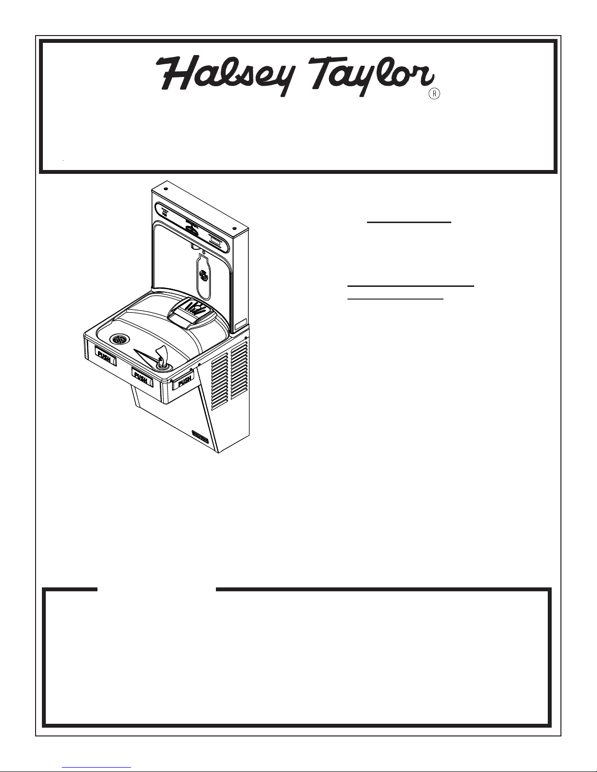
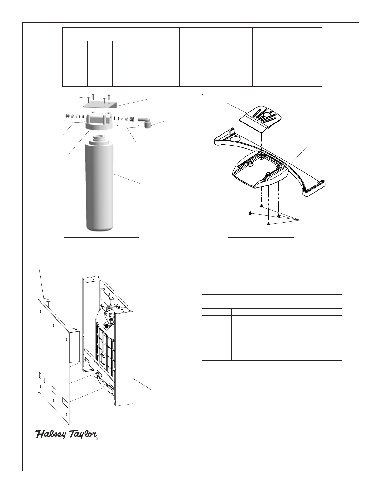
TO CHANGE THE FILTER:
1) Remove the lower front panel of the watercooler by removing the four (4) screws
2) Turn inlet water valve off.
3) Open bubbler to relieve pressure build-up in the system.
4) Remove filter from head by rotating filter counterclockwise.
5) Remove new filter from carton, remove protective cap; cap may be placed on old filter to reduce the chance of water spilling from
filter housing.
6) Attach filter to filter head by firmly inserting into head and rotating filter clockwise.
7) Turn on water supply and hold open the bubbler on cooler until approximately 1 gallon of water is dispensed. This flushing
procedure purges air and fine carbon particles from the filter.
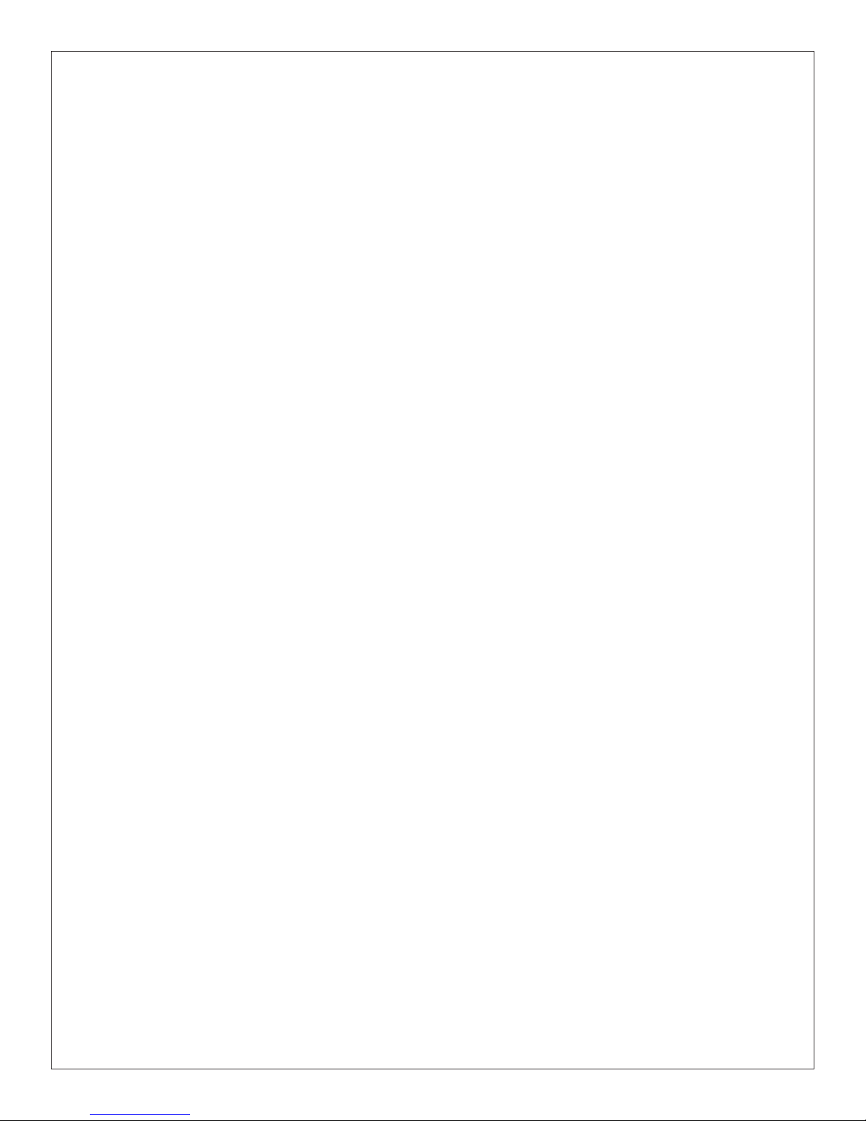
TO RESET THE FILTER MONITOR:
1) In order to reset the visual filter monitor status LED’s, you must remove the top cover of the bottle filler. Remove the two (2) screws
with a 5/32 allen wrench holding top cover to Bottle Filler. Remove top cover. Do not discard mounting screws, they will be needed
to reinstall the top cover
2) With your finger, reach inside the opening and depress the program button located behind the LCD display outside of the electron-
ics cover for approximately 2 seconds until the display changes then release. The display will change and scroll through three
messages:
“RST FLTR” – Reset Filter Status LED
“RST BCNT” – Reset Bottle Count
“RNG SET” – Range Set for IR Sensor
If the program button is not pushed again the display will scroll through the three messages above for three cycles and then default
back to bottle count and be back in run mode.
3) When the display changes to “RST FLTR”, depress the button again. The display will change to show “FLT =”. Depress the button
again and the display will show “FLTR =0”
4) The Green LED should be illuminated indicating that the visual filter monitor has been reset. Reinstall the top cover.
SETTING THE CONTROL BOARD – SETTING RANGE OF THE IR SENSOR
1) In order to access the programming button, you must remove the top cover of the bottle filler. Remove the two (2) screws with a
5/32” allen wrench holding top cover to Bottle Filler. Remove top cover. Do not discard mounting screws, they will be needed to
reinstall the top cover
2) With your finger, reach inside the opening and depress the program button located behind the LCD display outside of the
electronics cover for approximately 2 seconds until the display changes then release. The display will change and scroll through
three messages:
“RST FLTR” – Reset Filter Status LED
“RST BCNT” – Reset Bottle Count
“RNG SET” – Range Set for IR Sensor
If the program button is not pushed again the display will scroll through the three messages above for three cycles and then default
back to bottle count and be back in run mode.
1) To set the RANGE of IR Sensor: when display shows “RNG SET” push program button once the display will show current value (can
be 1 – 10) i.e. “RNG = 3”.
2) Once display shows current value push the program button to scroll through value of 1 – 10. Select the desired range setting.
3) Once range is selected allow approximately 4 seconds to pass and then the display will go back to bottle counter and be in run
mode.
4) Test bottle filler by placing bottle or hand in front of sensor to make sure water is dispensed.
SETTING THE CONTROL BOARD – RESETTING BOTTLE COUNT
1) In order to access the programming button, you must remove the top cover of the bottle filler. Remove the two (2) screws with a 5/
32 allen wrench holding top cover to Bottle Filler. Remove top cover. Do not discard mounting screws, they will be needed to
reinstall the top cover
2) With your finger, reach inside the opening and depress the program button located behind the LCD display outside of the electron-
ics cover for approximately 2 seconds until the display changes then release. The display will change and scroll through three
messages:
“RST FLTR” – Reset Filter Status LED
“RST BCNT” – Reset Bottle Count
“RNG SET” – Range Set for IR Sensor
If the program button is not pushed again the display will scroll through the three messages above for three cycles and then default
back run mode which display bottle count.
3) To reset the BOTTLE COUNTER: when display shows “RST BCNT” push program button once the display will show current value
i.e. “BC0033183”.
4) Once display shows current value push the program button once more to reset back to 0. The display will show BTLCT = 0 for
approximately 2 seconds and then return to run mode showing 00000000 bottles.
5) To test bottle counter, you can place bottle or hand in front of sensor for approx 5 seconds to see bottle counter count 00000001.
(This is based on filling a 16 oz bottle)

Page 698658C (Rev. B - 1/11)
HACFSCWSD*1D HAC8FSCWSBLQ*1D HACFSCDWSBL*1D HAC8FSCWSBLQ*1D HACFSCWSDBL*1D
BOTTLE FILLING UNIT
1
2
3
4
5
6
7
Fig. 7
WATER FILTER EXPLODED VIEW
DESCRIPTION
1
2
3
4
5
6
7
ITEM NO. PART NO.
51294C
70792C
70823C
70822C
55898C
70818C
28641C
Filter Head Assy.
Screw #8-18 x .75 PH
Fitting - Superseal 3/8” (10 mm)
Fitting - Superseal 1/4” (6 mm)
Filter Assy
Elbow - 3/8” (10mm)
Bracket
DESCRIPCIÓN DESCRIPTION
Ensamblado de la Cabeza del Filtro
Tornillo #8-18 x .75 PH
Accesorio - Supersello 3/8" (10mm)
Accesorio - Supersello 1/4" (6 mm)
Ensamblado del Filtro
Codo - 3/8" (10 mm)
Fijador
Ens. de tête de filtre
Vis #8-18 x .75 hp
Raccord - Superseal 3/8" (10mm)
Raccord - Superseal 1/4" (6mm)
Ens. filtre
Coude - 3/8" (10mm)
Support
WATERSENTRY® PLUS FILTER PARTS LIST
(See Fig. 7)
LISTA DE PIEZAS DEL FILTRO
(Vea Fig. 7)
LISTE DES PIÈCES DU FILTRE
(Voir Fig. 7)
DRAIN MAT EXPLODED VIEW
Fig. 8
Screws
Drain Cover
Drain Mat
DESCRIPTION
98543C
98544C
98545C
98546C
98666C
98667C
98549C
98668C
98552C
Kit - Electrical Package
Kit - IR Sensor
Kit - Solenoid Valve Replacement
Kit - Aerator Replacement
Kit - Top Cover Replacement
Kit - Drain Mat & Cover Replacement
Kit - Hardware & Waterway Parts
Kit - Filter Mounting Cover
Kit - Retro Filter Mounting
REPLACEMENT PART KITS
PART NO.
DRAIN MAT ASSEMBLY AND CARE
1) Place Drain Cover on mat and install the four screws as shown in Fig. 8.
2) It is recommended that the cover be removed and the drain cover be
cleaned weekly. To dis-assemble or re-assemble the drain cover the mat
can be picked up from the front to access the screws beneath.
WALL MOUNTING PLATE
Fig. 9
PRINTED IN U.S.A.
FOR PARTS CONTACT YOUR LOCAL DISTRIBUTOR OR VISIT OUR WEBSITE WWW.HALSEYTAYLOR.COM
PARA PIEZAS DE REEMPLAZO PÓNGASE EN CONTACTO CON SU DISTRIBUIDOR LOCAL O VISITE NUESTRO SITIO DE WEB WWW.HALSEYTAYLOR.COM
POUR VOUS PROCURER DES PIOCES, CONTACTEZ VOTRE DISTRIBUTEUR LOCAL OU VISITEZ NOTRE SITE WEB A L’ADRESSE WWW.HALSEYTAYLOR.COM
2222 CAMDEN COURT
OAK BROOK, IL 60523
630.574.3500
Other manuals for HTHB-HAC
1
Table of contents
Other Halsey Taylor Freezer manuals