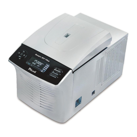
Hanil HyperCOOL HC3055 User manual

Operation Manual
HyperCOOL
HC3055 / HC3110
Product Model Name :
Date of Purchase :

HyperCOOL
HC3055/HC3110
© 2018 Hanil Scientic Inc.
If you have any questions, contact our Technical Support Center.
+82-2-3452-8966 / [email protected]om
www.ihanil.com
The appearance or specications of the device is subject to partial change for improvement.
HyperCOOL_HC3055_3110_Ver0.1

INDEX
1. Safety Precautions ---------------------------------- 4
1.1 Using this manual - 4
1.2 Safety Labels on the Device - 4
1.3 Safety Precautions - 5
2. Product Description -------------------------------- 6
2.1 Product Description - 6
2.2 Delivery Package - 7
2.3 Technical Specications - 8
3. Installation -------------------------------------------- 9
3.1 Wheel Lock - 9
3.2 Switching On the Device - 9
3.3 HyperCOOL Connection - 10
4. Operation ---------------------------------------------- 14
4.1 Key Functions of Control Panel - 14
4.2 Display - 15
4.3 Defrost - 15
4.4 Vacuum- 16
4.5 Time - 17
4.6 Keylock -18
5. Maintenance ------------------------------------------ 19
5.1 Outer Part of the Instrument - 19
5.2 Inside the Chamber - 19
5.3 Removing Dirt on the Condenser - 19
5.4 Fuse Replacement - 20
6. Troubleshooting ------------------------------------- 21
6.1 Possible Problems - 21
6.2 Error Codes - 22
6.3 Compliance - 23
7. Ordering Information ------------------------------ 24
The appearance or specications of the device is subject to partial change for improvement.

www.ihanil.com
4 / 26
1. Safety Precautions
This manual is for the users who operate the device for the rst time.
This manual provides information on the detailed instructions, precaution, troubleshooting
and maintenance care.
Keep this manual nearby for future reference.
The labels on the device represent safety instructions and directions.
Attention and warning
Attention and warning for
electric shock
1.1 Using this manual
1.2 Safety Labels on the Device

1. Safety Precautions
Before using the device, please read this operation manual to ensure correct usage. Incorrect
handling of the device may possibly result in personal injury or physical damage on the
device or its accessories.
1. ALWAYS locate the device on a at, rigid and stable table capable of withstanding the
weight of the device and its operation.
2. ALWAYS make a safety zone of 30 cm around the device to indicate that neither
hazardous materials nor persons should be permitted within the area during operation.
▶ ALWAYS position the device with enough space on each side of device to ensure
proper air circulation.
3. The line voltage of the installation site should be within the rated voltage of this product. If
not complied, the device can be damaged.
4. Only use accessories manufactured by Hanil Scientic Inc. Hanil Scientic Inc. does not
guarantees any problems occurred by using incompatible accessories.
5. Remove any contaminants inside the chamber before operating the device.
6. Should not use ammable, toxic, radioactive, explosive or corrosive materials.
7. The containers should be kept level while drying the samples in them.
8. Any kind of device repair must be performed only by Hanil Scientic Inc. authorized service
engineers.
9. A proper disinfection procedure should be carried out before delivering the device to
service engineer.
10. Maintain all the accessories dry and clean to keep the best condition and to increase the
lifespan.
11. Avoid exposing the device to direct sunlight, extreme temperatures, or moisture.
1.3 Safety Precautions

www.ihanil.com
6 / 26
2. Product Description
2.1 Product Description
[Back side of the device]
[Right side of the device]
① ② ③ ④
⑤
⑦
⑥
①Vacuum Release Valve
②Tube Connection to Vacuum Pump
③Mains Inlet
④Power Outlet for Vacuum Pump
⑤Mains Switch
⑥Air Inlet
⑦ Drain Valve

2. Product Description
2.2 Delivery Package
- Hyper COOL 3055/3110
- AC Power Cable
- Hose
- Operation Manual
- Clamp
· Check all parts for damage that may have occurred during transportation.
· Check the delivery for completeness.

www.ihanil.com
8 / 26
2. Product Description
2.3 Technical Specications
HC3055
HC3110
Ultimate Chamber Temp (at RT) (℃) -55 -110
Chamber Volume (L) 4
Trap (Chamber) Size (Ø x L) 165 x 202
ICE Condensing Capacity (kg) 3
ICE Condensing Performance (kg/day) 2.5
Compressor 1/2HP
1/2HP x 2
Refrigerant R507
R507/R1150
Power Requirement (Resting, VA) 642 819
Dimension (W x D x H, mm) 400 x 660 x 570
Weight (kg)
58 72
Digital Readout
Temperature, Time
Function
KEYLOCK, DEFROST , VACUUM, TIME
- Hyper COOL 3055/3110
- AC Power Cable
- Hose
- Operation Manual
- Clamp

3.2 Switching On the Device
· After installing the device, lock the wheel to prevent the device from moving.
3. Installation
3.1 Wheel Lock
1. Connect the AC power cord to the power socket on the backside of the device and put the
plug into a power outlet.
▶ Check the proper power and the fuse specication.
2. Switch the device on by pressing the mains switch on the right side of the device.
Turn on the switch to [ I ].
1. Press the lever of the swivel caster to lock the wheel.

www.ihanil.com
10/26
3. Installation
3.3 HyperCOOL Connection
[HyperCOOL as a 'Freezer Dryer']
①
②
③
④⑤
⑥
⑦
⑤
①Rubber Valve Closed
②Tube Connection to Vacuum Pump
③Mains Inlet
④Vacuum Pump to Power Outlet
⑤Vacuum Pump to HyperCOOL
⑥Power Outlet for Vacuum Pump
⑦ Rubber Valve Open

3. Installation
3.3 HyperCOOL Connection
[Preparation of Chamber]
1. Ensure all the vacuum valves are rmly closed.
2. Ensure all the connections and attachment from the chamber are tightly sealed.
3. Ensure the drain valve does not contain any water.
4. Ensure both the drain valve and the vacuum release valve are fully closed.
5. Check the status of all the rubber valve handles are closed.
[HyperCOOL as a 'Freezer Dryer']
[Preparation of Vacuum Pump]
1. Connect vacuum hose to the vacuum pump inlet and rmly clamp it not to
release vacuum.
2. Connect vacuum hose to the HyperVAC vacuum nozzle and rmly clamp it.
[Preparation of Accessories]
1. Chamber or manifold should be mounted on top of HyperCOOL for freeze-drying
samples.
2. Ensure all the connections are tightly sealed.
Close Opened Vacuum Release

www.ihanil.com
12/26
3. Installation
3.3 HyperCOOL Connection
[HyperCOOL as a 'Cold Trap']
[Preparation]
DEFROST should be performed only when the vacuum pump is o.
While DEFROST function is activated, HyperVAC (the vacuum concentrator) should be run
at lower than 1,000 rpm not to turn on the vacuum pump.
①Rubber Valve Closed
②Tube Connection to Vacuum Pump
③Mains Inlet
④Vacuum Pump to HyperCOOL
⑤Vacuum Pump to Power Outlet
⑥Mains Inlet
⑦ HyperCOOL to HyperVAC
⑧ Rubber Valve Open
①
②
③
④⑤
⑤
⑥
⑦
⑧

3. Installation
3.3 HyperCOOL Connection
[HyperCOOL (HC-CPP) as a ‘Cold Trap’]
[Preparation]
DEFROST should be performed only when the vacuum pump is o.
While DEFROST function is activated, HyperVAC (the vacuum concentrator) should
be run at lower than 1,000 rpm not to turn on the vacuum pump.
①Tube Connection to Vacuum Pump
②Mains Inlet
③Vacuum Pump to HyperCOOL
④Vacuum Pump to Power Outlet
⑤Mains Inlet
⑥HyperCOOL to HyperVAC
①
②③④
⑤⑥

www.ihanil.com
14/26
4. Operation
4.1 Key Functions of Control Panel
[KEYLOCK]
DEFROST, VACUUM or TIME function can be
locked during operation.
▶ Locked: LED On
[DEFROST]
Chamber defrosting by hot gas injection.
[VACUUM]
Turning on/o the vacuum pump.
▶ -30℃~RT : VACUUM inactive (LED ashing)
▶ <-30℃ : VACUUM activated (LED ashing)
▶ VACUUM ON(LED ON)
▶ < -50℃ : automatic pump on(LED on)
[TIME]
LED On: TIME setting mode
▶ Set H:M using the control buttons.
(←, ▲, ▼, SET)
[Display]
Actual Temperature(℃) and
Operating Time(H:M)
[POWER LED]
LED On : Main power on
[AWO LED]
LED HC -3055 HC -3110
ON < -50℃ < -90℃
Flashing (1 sec interval) - 50 ~ -20 ℃ - 90 ~ -20 ℃
Flashing (5 sec interval) > -20℃

4. Operation
4.2 Display
4.3 Defrost
Temperature: displays actual
temperature. (℃)
Defrost function warms the wall of the condenser and facilitates
the release and easy removal of the “ice-plug”.
Time: displays operating time (H:M)
▶ The range of time displayed is
999 hours and 59 minutes.
Defrosting function is activated with the LED on
when the DEFROST button is pressed.
▶ Disconnect power from the pump before performing the Defrost function.
And vacuum release process should be followed not to allow additional moisture into
chamber. It can be done by opening the vacuum release valve on the backside of the
HyperCOOL and will take up to a minute.
▶ After the vacuum release process, press the DEFROST button to start defrosting.
▶ Open the drain valve to remove the water melted from the chamber ice.
▶ The residual water should be removed before starting new process.
Turn the drain valve counterclockwise, to remove it
completely from the drain pipe.
Drain valve
Drain pipe

www.ihanil.com
16/26
4. Operation
4.4 Vacuum
VACUUM function is to turn on or o the vacuum pump, where the VACUUL LED indicates
current status of the vacuum pump.
▶ While the vacuum pump is resting, the VACUUM LED ashes.
▶ While the vacuum pump is running, the VACUUM LED is ON.
The vacuum pump is turned o by pressing VACUUM button.
1. Press VACUUM button to evacuate the
HyperCOOL chamber.
2. When the pump is on, it turns o by pressing
the VACUUM button. The HyperCOOL allows air
into the chamber by opening the vacuum release
valve on the backside.
Vacuum release valve
▶ The vacuum release can be adjusted by turning the
release valve.
(1) Vacuum: Tightened the valve by turning clockwise
(2) Vacuum release: Loosened the valve by turning
counterclockwise
▶ VACUUM LED ashes when the vacuum
pump is o and turns on when the
pump starts to operate.
▶ When the temperature of the condenser reaches -50℃, the vacuum pump automatically
starts to operate.
The pump can turn on by pressing the VACUUM button when the temperature reaches -30℃.

4. Operation
4.5 Time
Operating time can be set up to 999 hours and 59 minutes, or ‘continuous running’ is also
available.
(Up) (Down)
* Time LED Status
- LED OFF : at continuous running mode (00:00)
- LED ashing : at TIME setting mode
- LED ON : at running for the set TIME
1. Press the TIME button.
2. Press the DEFROST(up) or VACUUM
(down) button to up or down the value.
3. Press the TIME button to x the value.
4. When the operation is completed,
"End" message comes up with beep sound.
▶ At continuous running mode (0:00), time counts up from (0:00).
▶ When the DEFROST(up) button is kept pressed, ‘M’ increases till it reaches 59 minutes.
‘H’ follows afterwards and goes up acceleratedly.
▶ The TIME setting can be canceled by pressing KEYLOCK button.
▶ The factory default setting is continuous running mode (0:00).
▶ Press any button (KEYLOCK, DEFROST, VACUUM or TIME) to silence the beep sound.

www.ihanil.com
18/26
4. Operation
4.6 Keylock
The KEYLOCK function is available to prevent unwanted interruption of operation or change
of the current setting.
1. The Keylock mode is activated when
the KEYLOCK button is pressed.
2. The Keylock mode is deactivated by
pressing KEYLOCK once again.
▶ When KEYLOCK LED turns on, all the other buttons are frozen to prevent parameter change.

5. Maintenance
5.1 Outer Part of the Device
5.2 Inside the Chamber
5.3 Removing Dirt on the Condenser
1. Clean the outside of the device with dry soft cloth.
If necessary, dip the cloth in neutral detergent and clean any contaminants.
Keep it completely dry after cleaning.
2. Do not use any volatile chemicals such as alcohol, benzene, benzole, and thinner, etc.
3. Be careful not to make scratches on the surface of the device.
▶ Scratches may cause corrosion on the surface of the device.
▶ Rusted parts should be cleaned with neutral detergents and kept dry.
1. Keep dry inside the chamber after every use.
2. If the chamber is contaminated, clean contaminated area with the cloth dipped in neutral
detergent.
Dirt should be removed periodically to keep the best performance of the condenser.
The electric power should be OFF during the cleaning process.

www.ihanil.com
20/26
5. Maintenance
5.4 Fuse Replacement
Fuse replacement may be required when the main power does not turn on by switching on
the power. Please, follow the below instruction.
1. Remove the AC power cord and open the fuse case
using a (-) screw driver.
2. Replace the damaged fuse by the new spare fuse.
This manual suits for next models
1
Table of contents
Other Hanil Dryer manuals
