Hardy LC300 User manual

Model – LC300, LC500 & LC2500
INSTALLATION AND
OPERATING INSTRUCTIONS
FOR
THE HARDY
LIGHT COMMERCIAL
OUTSIDE WOOD BURNING HEATER
Model – LC300, LC500 & LC2500
HARDY MANUFACTURING
COMPANY, INC.
12345 ROAD 505
PHILADELPHIA, MS 39350
PHONE: (601) 656-5866
FAX: (601) 656-4559
www.hardyheater.com
Rev. 3/25/2015

THIS PAGE INTENTIONALLY LEFT BLANK

(MODEL LC300, LC500 & LC2500)
i
INTRODUCTION
Thank you for purchasing the original all stainless steel Hardy Outside Wood-Fired
Hydronic Heater. It represents the result of many years of Hardy experience and the
input of Hardy customers in the production of a top quality heater. With the purchase of
this Hardy Hydronic Heater, you can now appreciate the high degree of craftsmanship
and reliability that have made The Hardy the leader in the Outside Wood-Fired
Hydronic Heater field. This manual will provide you with a good basic understanding of
the installation and operation of this heater.
THIS MANUAL INCLUDES IMPORTANT SAFETY INFORMATION.
Your new heater should have the following:
(1) Owner’s manual complete with Installation
and Hook-Up Instructions
(2) Warranty & Return Warranty Card
(3) A tube of silicone (located in the firebox for shipping)
(4) Smoke stack and condenser tank stack both
with trim (located in the firebox for shipping)
(5) LC300 has two I-beams and three cast iron grates (located in the firebox)
LC500 has one I-beam, two channels and six grates (located in the firebox)
LC2500 has one air tube, two channels and six grates (located in firebox)
(6) Shovel (located in the firebox for shipping)
(7) Stainless steel panel and insulation that will be
located between the firebox door & ash door
after installation of the heater
(8) Hardy model LC500 has a stainless steel flame baffle (15” x 10”).
Hardy Model LC2500 has a welded steel baffle & 3/8” steel plate
Should your heater not have any of these items or if you have any questions regarding
the operation or maintenance of your heater, please consult you local Hardy dealer.
Again, thank you for purchasing a Hardy Outside Wood-Fired Hydronic Heater.
Sincerely,
Frank L. Moore
President
Hardy Manufacturing Company, Inc.

(MODEL LC300, LC500 & LC2500)
ii
Please fill in the following information
Hardy Model
Serial Number
Date of Purchase
Date of Installation
Dealer Purchased from
Dealer Address
Dealer Phone Number
HARDY MANUFACTURING COMPANY, INC.
12345 ROAD 505
PHILADELPHIA, MS 39350
PHONE: (601) 656-5866
www.hardyheater.com

(MODEL LC300, LC500 & LC2500)
iii
SAFETY PRECAUTIONS
WARNING
Do not operate this equipment for other than its intended purpose nor other
than in accordance with the instructions contained in this manual and all other
instructions accompanying the unit. For units covered by this instruction book, it is
important to observe safety precautions to protect yourself from possible injury. Among
the many considerations, you are advised to:
Observe all safety stickers on the unit.
This unit must be wired by a qualified electrician in accordance with the National
Electrical Code.
Never use any type of petroleum product, petroleum based product, charcoal
starter, lighter fluid, or any other flammable accelerant to start your unit.
Always open the ash door (bottom) before you open the firebox door (top).
Never leave the doors open, always latch the doors securely.
Always use proper care when installing, operating and maintaining the unit.
Do not modify the unit.
Do not substitute repairs which can be provided by your dealer, distributor, or
Hardy Manufacturing Company.
Failure to heed this warning or any additional warnings on the unit may result in an
accident causing personal injury.
Safety Labels and Rating Labels
Read all safety labels on this unit
5” X 3.5”
120,000
2.69
LC300-1-07

(MODEL LC300, LC500 & LC2500)
iv
Safety Labels
Read all safety labels on this unit
Name Plate Supplement
5” X 10” (not shown actual size)

(MODEL LC300, LC500 & LC2500)
v
Safety Labels
Read all safety labels on this unit
Heater Wiring Diagram
3” X 8”
R
WATER VALVE
LIQUID LEVEL
SWITCH
M
PUMP MOTOR
RELAY
R3
M
DAMPER BLOWER
MOTOR
DAMPER
AQUASTAT
M
PUMP MOTOR
RELAY
R3
OPTIONAL
SECOND
HEATING
ZONE
GROUND FAULT
CIRCUIT
INTERRUPTER
L 1
L 2
DAMPER SOLENOID
R
LLS
46
R 3
4 6
R 3
T1 BM
PM
PM
W V
SOL
GFCI L 2
L 1
LEGEND
GFCI GROUND FAULT CIRCUIT INTERRUPTER
LLS LIQUID LEVEL SWITCH
WV WATER SOLENOID VALVE
(OPTIONAL ON H3 & H5)
R3 CIRCULATOR PUMP RELAY
PM WATER CIRCULATOR PUMP
T1 DAMPER AQUASTAT
BM DAMPER BLOWER MOTOR
SOL DAMPER SOLENOID
R LOW WATER LIGHT
HEATER WIRING DIAGRAMS
CONNECTION DIAGRAM
SCHEM ATIC DIAGRAM

(MODEL LC300, LC500 & LC2500)
vi
Safety Labels
Read all safety labels on this unit
Warning label for Condenser Vent
5” X 3”
Back Door label
5” X 3”

(MODEL LC300, LC500 & LC2500)
vii
Safety Labels
Read all safety labels on this unit
Warning label on front between doors
4” X 2 3/4”
Field wiring label
2 3/4” X 1”
Hot water label
2 3/4” X 1”

(MODEL LC300, LC500 & LC2500)
viii
THIS PAGE INTENTIONALLY LEFT BLANK

(MODEL LC300, LC500 & LC2500)
ix
OUTDOOR WOOD HEATER BEST BURN PRACTICES
1.1. Read and follow all operating instructions supplied by the manufacturer.
2. FUEL USED: Only those listed fuels recommended by the manufacturer of your unit.
Never use the following: trash, plastics, gasoline, rubber, naphtha, household
garbage, material treated with petroleum products (particle board, railroad ties and
pressure treated wood), leaves, paper products, and cardboard.
3. LOADING FUEL: For a more efficient burn, pay careful attention to loading times and
amounts. Follow the manufacturer’s written instructions for recommended loading
times and amounts.
4. STARTERS: Do not use lighter fluids, gasoline, or chemicals.
5. LOCATION: It is recommended that the unit be located with due consideration to the
prevailing wind direction.
6. Always remember to comply with all applicable state and local codes.
Outdoor Furnace Manufacturers Caucus
• Furnace should be located no less than 100 feet from any building not served by
the furnace.
• If located within 100 feet to 300 feet to any building not served by the furnace, it
is recommended that the stack be at least 2 feet higher than the peak of that
building.
Chimney Height Installation Scenario
Building
served by furnace
Building not
served by furnace
Chimney height
should be 2 feet above roof line.
2 feet
Minimum of 100 feet
Acme

(MODEL LC300, LC500 & LC2500)
x
THE HARDY OUTSIDE WOOD-FIRED HYDRONIC HEATER
How does The Hardy work?
The Hardy Outside Wood-Fired Hydronic heater is designed to save the most energy
and provide the most comfortable heating available. It heats your building by heating a
stainless steel tank filled with water, which surrounds the firebox of the outside heater.
The heater is basically a non pressurized boiler with an atmospheric vent. This hot
water is then circulated through underground hot water pipes to a water coil inside your
existing central duct system. The Hardy Hydronic Heater can be connected to any
existing hydronic heating system that operates at 180 degrees or less.
How do the thermostat controls work?
The only visible addition to the heating system inside the building is a thermostat which
is located near the existing thermostat. The two thermostats are installed so that if the
outside wood heater is not in operation, your existing unit will automatically take over to
maintain the building temperature. The wall thermostat which regulates the heat from
the outside heater performs two functions; when it senses the need for heat, it turns
the water pump on to circulate the hot water through the coil and also turns the blower
on inside your central unit to force air across the hot coil. This forces hot air into your
central duct system. The outside heater has a hot water thermostat which senses the
water temperature of the unit. If the water is not as hot as the thermostat setting then
the combustion air intake is automatically opened and remains open until such
temperature is attained.
What are acceptable installations?
These units are designed and approved for installation in light commercial
environments. In accordance to Federal New Source Performance Standards (NSPS)
for New Residential Hydronic Heaters these units are not for sale, installation, or
operation in a residential application.
Where should The Hardy be located?
The outside unit should be located at least 10 feet from the building be served so that
all fire danger is removed. The unit may be installed as much as 100 feet away and still
heat the building . If the unit is located more than 100 feet away, you may experience
some heat loss and require larger supply and return lines to maintain proper flow rates.
Locate the heater where it will be convenient for refueling and wood storage. All water
and power lines are installed underground between the building and the heater.

(MODEL LC300, LC500 & LC2500)
xi
TABLE OF CONTENTS
SECTION I: General Information
1-1 Specifications............................................................1-2
1-2 Heater Component Parts Model LC300 .......................3
1-3 Heater Component Parts Model LC500 .......................4
1-4 Heater Component Parts Model LC2500 .....................5
SECTION II: Installation of Heater
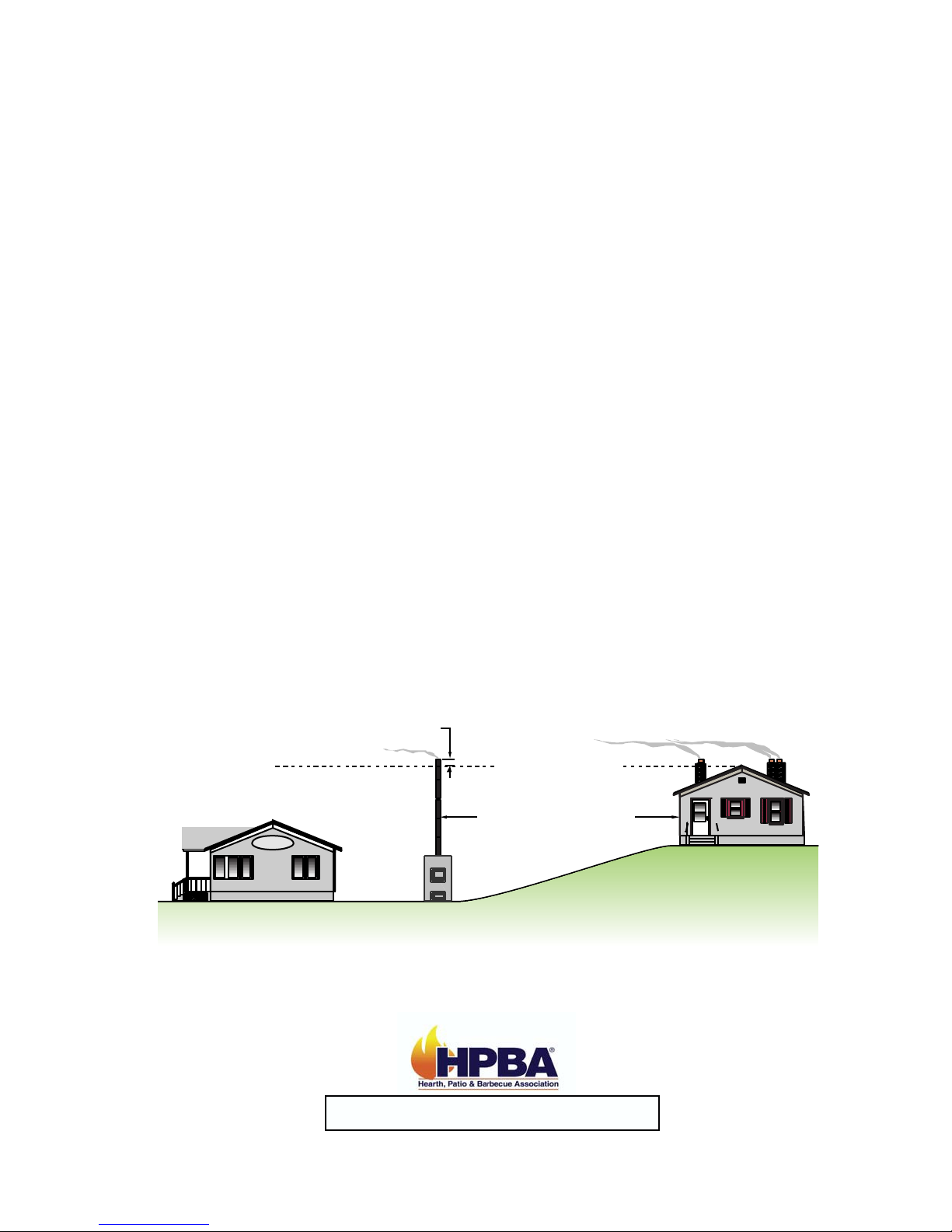
2-1 Location of Heater.....................................................6-7
2-2 Chimney Connection....................................................7
2-3 Hull Removal................................................................8
2-4 Set-Up of Grates .....................................................9-10
2-5 Location of Plumbing & Electrical Lines .....................11
2-6 Connection of Power to Heater ..................................12
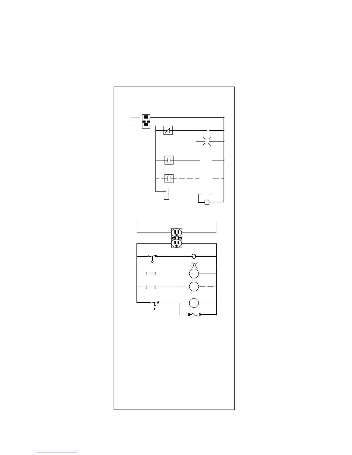
2-7 Wiring Diagram .....................................................13-14
SECTION III: Plumbing Instructions
3-1 Instructions for forced air systems .............................15
3-2 Location of heating coil.........................................16-17
3-3 Instructions for Hydronic systems.........................18-19
3-4 Instructions for Water Heater Hookups LC300 , LC500,
& LC2500 ..................................................................20
3-5 Replacing Hull ...........................................................21
3-6 Filling the Heater with water ......................................22
SECTION IV: Connection to Central Heating/AC System
4-1 Connection to Central Unit
with Existing Blower Relay ...................................23-24
4-2 Connection to Central Unit
with Existing Blower Relay Diagram .........................25
SECTION V: Heater Operation
5-1 Firing the Heater ........................................................26
5-2 Water Temperature ...................................................26
5-3 Moisture in the Firebox ..............................................26
5-4 Wood Usage..............................................................27
5-5 Improper Burning.......................................................27
5-6 Ash Removal .............................................................27
5-7 Ash Disposal .............................................................27
5-8 Creosote Formation and Removal.............................28

(MODEL LC300, LC500 & LC2500)
xii
SECTION VI: Service Information
6-1 Electric Make-Up Water System................................29
6-2 Water Circulation System ..........................................30
6-3 Temperature Control System ....................................31
SECTION VII: Heater Maintenance
7-1 Preventative Maintenance .........................................32
7-2 Preseason Maintenance.......................................33-34
7-3 In Season Maintenance........................................34-35
7-4 Post Season Maintenance.........................................35
SECTION VIII: Appendix
8-1 General Trouble Shooting Guide ..........................36-43
8-2 Circulator Maintenance Instructions ......................44-45
8-3 Damper Solenoid Replacement Instructions ..............46
8-4 Low Water Switch Replacement Instructions ........47-48
8-5 Draft Blower Replacement Instructions .................49-50
8-6 Automatic water fill Replacement Instructions.......51-52
8-7 Aqua stat Replacement Instructions......................53-55

HARDY MANUFACTURING CO., INC (MODEL LC300, LC500 & LC2500) PAGE 1
SECTION I
GENERAL INFORMATION
1-1 Specifications
Type of fuel –Clean Seasoned Hard Wood - Clean wood means wood that has no
paint, stains, or other types of coatings, and wood that has not been treated with
preservatives, including but not limited to, copper chromium arsenate, creosote, or
pentachlorophenol.
For outdoor use only
Electrical Rating 115 VAC/ 60 HZ / 1PH
MFS-15 AMP, MCA-15 AMP
Clearance to Combustibles
Top, Rear, Sides 48”
Chimney Connector 48”
Front 48”
Flooring Non Combustible
Water Capacity
LC300 –Holds Approximately 100 Gallons of Water
LC500 –Holds Approximately 130 Gallons of Water
LC2500 –Holds Approximately 160 Gallons of Water
Heater Dimensions
Description Width Depth Height Weight
LC300 –120,000 BTU 30” 52 ½” 59 ½” 650 lbs.
LC500 –180,000 BTU 40” 52 ½” 59 ½“ 850 lbs.
LC2500 –250,000 BTU 40” 60 ½“ 59 ½“ 1000 lbs.
Firebox sizes
Description Width Depth Height
LC300 –120,000 BTU 24” 32” 36” + 8” for Grates
LC500 –180,000 BTU 34” 32” 36” + 8” for Grates
LC2500 –250,000 BTU 34” 30” 44” + 8” for grates
Chimney
Description Size OD Material
LC300 –120,000 BTU 6” Stainless Steel, Single wall
LC500 –180,000 BTU 8” Stainless Steel, Single wall
LC2500 –250,000 BTU 8” x 10” Stainless Steel, Double wall

HARDY MANUFACTURING CO., INC (MODEL LC300, LC500 & LC2500) PAGE 2
On the front of your heater there is a nameplate. Along with other information you will
find the model number of your heater. This model number tells you what your heater
rating is and what electrical and plumbing options your heater has, use the following
list to determine this. The first section determines the rating of your heater. The second
section determines electrical options. The last section determines the plumbing
options. For example heater model number LC300-1-07. The LC300 designates that
you have a 120,000 BTU heater. The 1in the second section designates that you have
a standard pump. The 0in the last section designates that you have no hot water coil.
The 7in the last section designates that you have extra ports on your heater.
Heater Rating
LC300 –120,000 BTU
LC500 –180,000 BTU
LC2500 –250,000 BTU
120,000
2.69
WOOD
LC300-1-07
1-1 Specifications
Electrical Options
0 –Without a Pump
1 –Standard Pump
2 –2nd Pump & Relay
3 –3rd Pump & Relay
4 –Without a Pump for Heating System
and with Circulating Hot Water
5 –With a Standard Pump for Heating System
and with Circulating Hot Water
6 –With 2nd Pump and Relay and with
Circulating Hot Water
7 –With 3rd Pump and Relay and with
Circulating Hot Water
8 –Optional External Plate & Circulator
9 –Optional automatic water fill
Plumbing Options
0 –Without Hot Water
1 –Standard Hot Water
2 –With 2nd Heat Exchanger (2nd Hot Water or
Swimming Pool heat exchanger)
3 –With 3rd Heat Exchanger (2nd Hot Water and
Swimming Pool Heat Exchanger)
4 –Extra 60’ copper in Hot Water
5 –Extra 60’ copper in Hot Water
and Swimming Pool Heat Exchanger
6 –1” Heat Exchanger –2 –60’ Rolls 3/4” Copper
Manifold to 1” Ports
7 –Extra Ports, 1/2”, 3/4”, 1”, etc.
Model Electric options Plumbing options

HARDY MANUFACTURING CO., INC (MODEL LC300, LC500 & LC2500) PAGE 3
1-2 Heater Component Parts Model LC300
29
27
26
25
24
23
21
20
19
18
17
16
15
14
13
13
12
11
11
28
22
10
9
8
7
7
776
5
4
3
2
1Part No. Description
1 600.10 1/2” Brass Elbow
2 810.00 1/2” Overflow Pipe
3 1100.28 Low Water Switch
4 602.16 3/4” Brass Tee
5 603.40 3/4” x Close Brass Nipple
6 600.30 3/4” Brass Elbow
7 604.32 3/4” Brass Cap
8 604.16 1/2” Brass Cap
9 2000.48 1/2” Well Fitting
10 2000.08 Honeywell Aqua stat
11 603.32 3/4” x 6” Brass Nipple
12 607.12 3/4” Brass Ball Valve
13 502.60 3/4” SS flange
14 502.50 Taco 009 SS Circulator
15 2004.40 Wire Connectors
16 1100.30 Low Water Light
17 2000.52 Honeywell Relay
18 2001.05 Damper Solenoid
19 2004.00 GFCI Receptacle
20 2004.16 Receptacle box 2 1/8” deep
21 3200.12 Jack Chain
22 3200.16 Key Ring
23 2002.16 100 CFM Blower / Lid
24 2004.28 Plastic Romex Connector
25 607.42 3/4” Boiler Drain
26 2004.04 3’ 3 Wire Power Cord
27 2004.08 8’ 2 Wire Power Cord
28 2004.52 Electrical Mounting Panel
29 604.00 1/4” Brass Cap
12

HARDY MANUFACTURING CO., INC (MODEL LC300, LC500 & LC2500) PAGE 4
1-3 Heater Component Parts Model LC500
Part No. Description
1 600.10 1/2” Brass Elbow
2 810.00 1/2” Overflow Pipe
3 1100.28 Low Water Switch
4 602.16 3/4” Brass Tee
5 603.40 3/4” x Close Brass Nipple
6 600.30 3/4” Brass Elbow
7 604.32 3/4” Brass Cap
8 604.16 1/2” Brass Cap
9 2000.48 1/2” Well Fitting
10 2000.08 Honeywell Aqua stat
11 603.32 3/4” x 6” Brass Nipple
12 607.12 3/4” Brass Ball Valve
13 502.60 3/4” SS flange
14 502.50 Taco 009 SS Circulator
15 2004.40 Wire Connectors
16 1100.30 Low Water Light
17 2000.52 Honeywell Relay
18 2001.05 Damper Solenoid
19 2004.00 GFCI Receptacle
20 2004.16 Receptacle box 2 1/8” deep
21 3200.12 Jack Chain
22 3200.16 Key Ring
23 2002.16 100 CFM Blower / Lid
24 2004.28 Plastic Romex Connector
25 607.42 3/4” Boiler Drain
26 2004.04 3’ 3 Wire Power Cord
27 2004.08 8’ 2 Wire Power Cord
28 2004.52 Electrical Mounting Panel
29 604.00 1/4” Brass Cap
29
27
26
25
24
23
21
20
19
18
17
16
15
14
13
13
12
11
11
28
22
10
9
8
7
7
7
76
5
3
2
1
12
4

HARDY MANUFACTURING CO., INC (MODEL LC300, LC500 & LC2500) PAGE 5
1-4 Heater Component Parts Model LC2500
1
2
3
4
5
6
7
8
9
10
11
12
13
14
15
16
17
18
19
13
20
20 20
21 22
23
24
25
26
27
27
28
27
Legend Part No. Description
1) 2000.16 Aquastat
2)1100.28Low Water Switch
3)1100.00 Water Solenoid
4)508.09 Taco 008
5)502.08 Taco 009
6)2000.52 Relay
7)2004.00 GFCI
8)2001.05Damper Solenoid
9)2002.30 130 CFM Blower
10) 300.02 Plate Exchanger
11) 600.10 1/2” Brass elbow
12) 810.00 1/2” Overflow pipe
13) 607.42 3/4” Male Boiler Drain Valve
14) 700.05 3/4” x 10” SS Flex Line
15) 700.18 3/4” x 18” SS Flex Line
16) 900.80 1 1/2” Copper Supply
17) 900.85 1 1/2” Copper Pump Supply
18) 900.90 1 1/2" Copper Return
19) 607.47 1 1/2” Brase Ball Valve
20) 607.45 1" Brass Ball Valve
21) 607.12 3/4" Brass Ball Valve
22) 607.00 1/2" Brass Ball Valve
23) 600.05 1/4" Brass Elbow
24) 603.04 1/4" X 4" Brass Nipple
25) 603.28 3/4” X 4” Brass Nipple
26) 600.30 3/4" Brass Elbow
27) 600.48 1 1/2” Brass Elbow
28) 1100.30 Low Water Indicator Light

HARDY MANUFACTURING CO., INC (MODEL LC300, LC500 & LC2500) PAGE 6
SECTION II
INSTALLATION OF HEATER
2-1 Location of Heater
The Hardy Hydronic Heater must be located outside the building to be heated. The unit
must be located a minimum of 10 feet from the building. The unit should be installed
upon a concrete pad. There are two typical installation options that we recommend.
Option 1 has the unit installed on concrete pad with the rear of the water tank flush with
the end of the pad. We recommend the pad to be 48” wide and 53” long minimum. If
you add extra length it will allow ample concrete in front of the heater for loading wood
and removing ashes. The space between the rear of the unit and the outside cover will
allow a 4” watertight pipe or other means to insulate the plumbing and electrical lines to
run directly into the ground. The outside cover can be removed by lifting it off the water
tank on all four corners. This will allow you easy access for the connection of the
plumbing and electrical lines.
Please see the illustration below for details.
58.000
48.000 20.000
14.000
6.000
Option 1
This manual suits for next models
2
Table of contents
Other Hardy Wood Stove manuals
Popular Wood Stove manuals by other brands

KASTOR
KASTOR KSIS Series Installation and usage manual

Drolet
Drolet Savannah Installation and operation manual

Supra
Supra ARIO Installation instructions and user manual

Masport
Masport Bowden Wood Stacker operating instructions

Residential Retreat
Residential Retreat RWS-424174MH owner's manual

Ashley
Ashley AW2020E-P Owner’s Instruction and Operation Manual

Quadra-Fire
Quadra-Fire 57ST-ACC owner's manual

SOLZAIMA
SOLZAIMA TEK Round Eco instruction manual

Century Heating
Century Heating S244 manual

Nectre Fireplaces
Nectre Fireplaces N65 operating instructions

Supra
Supra LYTHAM LIFT 2 Instructions for installation and use

Mendip Stoves
Mendip Stoves 600 instruction manual