HAWE Hydraulik EV2S-CAN Series Operator's manual

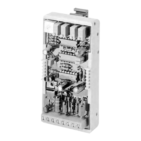
Electronic amplifier type EV2S-CAN
Product documentation
D 7818/1
09-2015-1.0
Line connector
Supply voltage UB: 8...32 V DC
Output current IA: max. 2 A

2 09-2015-1.0 - D 7818/1 - EV2S-CAN www.hawe.de | 2015
©by HAWE Hydraulik SE.
The forwarding and reproduction of this document, as well as the use and communication of its contents, are forbidden unless expresse-
ly permitted.
Any breach or infringement will result in liability for damages.
All rights reserved concerning patent or utility model registrations.

www.hawe.de | 2015 09-2015-1.0 - D 7818/1 - EV2S-CAN 3
Contents
1 Overview of type EV2S-CAN electronic amplifier.................................................................................................4
2 Available versions, main data............................................................................................................................5
3 Parameters....................................................................................................................................................... 6
3.1 General data......................................................................................................................................................6
3.2 Electrical parameters.......................................................................................................................................... 7
3.3 Communication.................................................................................................................................................. 8
3.4 Electromagnetic compatibility..............................................................................................................................8
4 Dimensions...................................................................................................................................................... 9
4.1 ....................................................................................................................................................................... 9
5 Installation, operation and maintenance information........................................................................................11
5.1 Electrical connection.........................................................................................................................................11
5.2 Operating instructions.......................................................................................................................................12
5.3 Instructions for adjustment with buttons............................................................................................................ 15
5.4 Initial operation (quick start)............................................................................................................................22
5.5 Instructions for setting up with software............................................................................................................ 26
5.6 Error management............................................................................................................................................ 27
6 Typical circuits............................................................................................................................................... 28
6.1 ..................................................................................................................................................................... 28
7 Additional version and use............................................................................................................................. 29

4 09-2015-1.0 - D 7818/1 - EV2S-CAN www.hawe.de | 2015
1Overview of type EV2S-CAN electronic amplifier
Proportional amplifiers actuate proportional solenoid valves by converting an
input signal into a corresponding control current.
The EV2S-CAN proportional amplifier is available for direct mounting onto a
solenoid valve as a plug amplifier.
It is suitable for controlling proportional single-action and twin solenoids. The
influences of temperature and power supply are compensated for by the feedback
measurement at the valve outputs, enabling the valve to behave consistently
accurately.
Important parameters (e.g. input signal, minimum current, maximum current,
dither, ramp times etc.) can either be set with a pushbutton and an integrated
display or via CAN bus via software on the computer.
Features and benefits:
■Direct assembly onto the solenoid valves
■Easy commissioning
■Up to two analogue inputs for target value signals
■Control of twin and single valves
■CAN bus interface
■Functions and settings tailored to HAWE products
Intended applications:
■For the control of proportional valves in mobile work machines and in the
industry sector
■Connection of analogue proportional valves in the CAN bus networks
■Closed control circuits
■Simple expansion of existing systems
Figure 1: Type EV2S-CAN electronic amplifier

www.hawe.de | 2015 09-2015-1.0 - D 7818/1 - EV2S-CAN 5
2Available versions, main data
EV 2 S - CAN - G - L3K
Interface option Table 2: Interface option
Plug type Table 1: Plug type
Target value input
Model
Number of solenoid outputs
Basic type
Table 1: Plug type
Marking Description
G Connector for single-action and twin solenoids with socket according to DIN EN 175 301-803 A
DG 2 x connectors for 2 single-action solenoids with socket according to DIN EN 175 301-803 A
Table 2: Interface option
Marking Description
L3K 3 m cable with open line ends 5 x 0.5 mm2
M M12 plug, 5-pole, only possible with plug type G

6 09-2015-1.0 - D 7818/1 - EV2S-CAN www.hawe.de | 2015
3Parameters
3.1 General data
Nomenclature Electronic amplifier
Design line connector
Connection leads •3m cable 5 x 0,5mm2
•M12, 5 pin
Fastening On socket to DIN EN 175 301-803 A
Installation position Any
Weight Approx. 70 g
Type of protect DIN VDE 0470, EN 60529 or
IEC 529 IP65 (mounted)
Ambient temperature -40...+80°C

www.hawe.de | 2015 09-2015-1.0 - D 7818/1 - EV2S-CAN 7
3.2 Electrical parameters
Supply voltage UB8 to 32 V DC, pole-protected
Output voltage UAUB– 0.5 V, pulse-width modulated
Unregulated output current IAmax. 0 to 2 A, short-circuit proof, temperature-dependent
Regulated output current IAmax. 0 to 1.6 A, short-circuit proof, temperature-dependent (see diagram 1)
Adjustment areas Imin 0 to 1 A
Imax 0 to 2A
Idle current IL<35 mA
Possible input signal 1 •0 to 5 V DC, RE= 36 kU
•0 to 10V DC, RE= 36 kU
•4 to 20 mA, RE= 220 kU
•0.25 UB… 0.75 UB, RE= 24 kU
•PWM, RE= 36 kU
Possible input signal 2 •0 to 5 V DC, RE= 24 kU
•0 to 10V DC, RE= 24 kU
•CAN
•*10 V DC, RE= 24 kU
Recommended target value potentiometer R Ò10 kU
Ramp time tR0 to 300 s
Increase and decrease time can be adjusted separately
Dither frequency f 50 to 1,000 Hz
Dither amplitude l 0 to 50%
PWM frequency f 50 to 1,000 Hz (temperature-dependent)

8 09-2015-1.0 - D 7818/1 - EV2S-CAN www.hawe.de | 2015
Temperature-dependent power during continuous operation
Figure 2: °C ambient temperature; I current (mA)
112 V systems
224V systems
3.3 Communication
CAN bus
CAN protocol CANopen, J1939
CAN baud rate 10, 20, 50, 100, 125, 250, 400, 500, 800, 1,000 (all units in kBaud)
CAN ID 1 to 127 (Default D = 126)
3.4 Electromagnetic compatibility
The EMC of the device was tested using an accredited testing agency (emitted interference according to EN 61000-6-3 and immunity to
interference according to EN 61000-6-2 evaluation criterion "B"). The test set-ups only represent typical use. This EMC testing does not
release the user from carrying out adequate prescribed EMC testing of their complete system (according to Directive 2004/108/EC). If
the EMC of the complete system must be further amplified, the following measures can be tested and introduced:
•Supply lines, such as inputs and outputs to and from the device, should be as short as possible. They should be shielded and twisted
in pairs (to reduce the antenna-like effect for increasing the immunity to interference), particularly if used in EMC-loaded applica-
tions.

www.hawe.de | 2015 09-2015-1.0 - D 7818/1 - EV2S-CAN 9
4Dimensions
All dimensions in mm, subject to change!
4.1 Board
Connection
1 Button - UP
2 Button - DOWN
3 Button - OK / Back
4 Display
5 LED - Power (green)
6 LED - A-side (green)
7 LED - B-side (orange)
8 LED - Error (red)
4.2 Plug type EV 2 S - CAN - G - L3K
4.3 Plug type EV 2 S - CAN - G - M

10 09-2015-1.0 - D 7818/1 - EV2S-CAN www.hawe.de | 2015
4.4 Plug type EV 2 S - CAN - DG - L3K

www.hawe.de | 2015 09-2015-1.0 - D 7818/1 - EV2S-CAN 11
5Installation, operation and maintenance information
5.1 Electrical connection
Connection pattern (magnet-side)
3-pole
IP 65 (IEC 60529)
EV 2 S - CAN - G - ...
Twin solenoid Single-action solenoid
EV 2 S - CAN - DG - L3K
2 single-action solenoids
Layout plan
Signal L3K M .. - M
Litz wire number M 12 pin
UB1 1
PGND / analogue input 1 GND 2 2
Analogue input 1 3 3
CANHIGH / analogue input 2 4 4
CANLOW / analogue input 2 GND 5 5

12 09-2015-1.0 - D 7818/1 - EV2S-CAN www.hawe.de | 2015
5.2 Operating instructions
CAN communication
In a CAN network with 11-bit identifier protocol, the type EV2S-CAN proportional amplifier can be connected according to CAN 2.0A;
with 29-bit identifier protocol, it can be connected according to CAN 2.0B.
Target values sent by a master can be converted into a valve current. An analogue sensor can also be read and the values sent to the
master via CAN bus.
The type EV2S-CAN proportional amplifier is delivered with the ID 126.
The baud rate can be freely selected between 10 and 1,000 kBaud. The standard value is 250 kBaud.
Input
Input signals can be directly converted into control current at the output. As there are many different input signals and customer
requirements, it is necessary to provide a description of the input signal and the subsequent action.
The way the plug amplifier should behave with the relevant input signal is defined with the user parameters in menu input 1 and input
2.
Example: 0.5 to 4.5 V DC joystick // twin valve
1Middle value
2Error bottom
3Maximum negative
4Minimum negative
5Minimum positive
6Maximum positive
7Error top

www.hawe.de | 2015 09-2015-1.0 - D 7818/1 - EV2S-CAN 13
Display
The two-digit seven-character display shows the abbreviation for the selected menu item or the value of the
selected user parameter within the menu structure. Values ranging from -9,999 to +99,999 may be shown. User
parameters with values ranging from 0 to 99 are shown directly in the character display. In order to be able to
display values greater than 99, the values are shown individually in thousands, hundreds, tens and unit blocks. The
display is similar to a combination lock.
Each block of values is displayed starting from the thousands by pressing OK. Pressing the OK button again in the single unit range
switches to the thousands range.
The current block of values is shown with two items in the display. At the top of the character display, the items light up at various
points depending on the block of values.
The negative numbers are displayed as follows. The symbol is only entered and displayed to the thousandth place. As a result,
the thousandth place must be decreased to the zero value by pressing the DOWN button. The symbol is then changed by pressing
and holding the DOWN button, if the value range permits this. By pressing the UP or DOWN button, the digits can be increased or
decreased as usual.
The standby function is displayed after successful initial operation. An item then flashes slowly and continuously in the right display
field. If an error occurs, an error code is displayed, which enables rapid troubleshooting.
Example 12,438 explains the display of positive values.
Values Coding Example
-9,000 - 99,000 Left and right item 12,000
100 - 900 Left item 400
10 - 90 Right item 30
1 - 9 No item 8
Example -5,678 explains the display of negative values.
Values Coding Example
-9,000 - 99,000 Left and right item 5,000
100 - 900 Left item 600
10 - 90 Right item 70
1 - 9 No item 8

14 09-2015-1.0 - D 7818/1 - EV2S-CAN www.hawe.de | 2015
LED displays
Four LEDs are built into the board to enable simple status monitoring. All the LEDs light
up once when the plug amplifier is started up.
Position Colour Description
1 Green Solenoid output A, active: Lights up when the output for the
A side is active
2 Red Error: Light for when an error is detected
3 Orange Solenoid output B, active: Lights up when the output for the
B side is active
4 Green Power: Lights up continuously when the device is correctly
supplied with voltage

www.hawe.de | 2015 09-2015-1.0 - D 7818/1 - EV2S-CAN 15
5.3 Instructions for adjustment with buttons
The plug can be parameterised using three buttons and a two-digit seven-segment display. All values can be selected, requested and
modified via the menu items using the three buttons. The designation of the selected parameter and the current values are shown in the
display.
Note
In order to be able to open the plug amplifier cover without risk of damage, the M3 tapped plug must first be fully removed. Do
not lose the O-ring seal provided!
Navigation
The individual menu items are selected using the UP and DOWN buttons in the
menu.
OK confirms the selection and takes you to the relevant submenu and/or user
parameters.
In order to return to the main menu, the OK button must be pressed until the
new menu item is displayed.
The user parameter values are also modified using the UP and DOWN buttons. The value is increased/decreased by pressing the button
once. Pressing and holding the button down automatically increases/decreases the value until the button is released. Modifications to
the user parameter are immediately saved.
If there is no input after more than 120 seconds, the menu is exited.
u
u
uu
V uV u
V u
V u
ssss

16 09-2015-1.0 - D 7818/1 - EV2S-CAN www.hawe.de | 2015
Menu
Press any button to access data in the parameter menu. Press the OK button to navigate further into the menu structure (change from
main menu to submenu 1).
Table: Main menu and submenu 1:
Main menu Display Submenu 1 Display
Password
(CP)
Reset
(Cr)
CAN
(Cc)
Configuration
(C_)
Valve type
(Cd)
Input 2
(A2)
Input
(A_)
Input 1
(A1)
Output 2
(P2)
Output
(P_)
Output 1
(P1)
Current target value
(AS)
Product information
(In)
Time
(rt)
Supply voltage
(Ub)
Data
(d_)
Temperature
(tE)

www.hawe.de | 2015 09-2015-1.0 - D 7818/1 - EV2S-CAN 17
Table: User parameter data:
Submenu 1 User parameters Display Minimum
value Maximum
value Description
Temperature
(tE)
Actual value display Temperature in °C
Supply voltage
(Ub)
Actual value display Supply voltage in mV
Runtime
(rr)
Actual value display Runtime since last reset in
h/min/sec
Time (rt)
Total runtime
(rh)
Actual value display Runtime since initial operation in
h
Hardware version
(hA)
Actual value display Serial number
Hardware
Software version
(S0)
Actual value display Version number
Software
Product information (In)
Serial number
(Sn)
Actual value display Serial number
Part No.
(tn)
Actual value display HAWE part number
Current target value
(AS)
Actual value display Actual, calculated target value

18 09-2015-1.0 - D 7818/1 - EV2S-CAN www.hawe.de | 2015
Table: User parameter output 1:
User parameters Display Minimum
value Maximum
value Description
Actual current 1
(AC)
Actual value display Actual current at the valve in mA
Minimum current 1
(IL)
0 1,000 Minimum current at actual value 0.1%
Maximum current 1
(Ih)
0 2,000 Maximum current at actual value 100%
Ramp, up 1
(rU)
0 30,000 1/100 sec
Ramp, down 1
(rd)
0 30,000 1/100 sec
Dither frequency 1
(dF)
0 16 According to table XXX
Dither amplitude 1
(dA)
0 98 In %
Resistance 1
(r0)
1 40 In U
Table: User parameter output 2:
User parameters Display Minimum
value Maximum
value Description
Actual current 2
(AC)
Actual value display Actual current at the valve in mA
Minimum current 2
(IL)
0 1,000 Minimum current at actual value 0.1%
Maximum current 2
(Ih)
0 2,000 Maximum current at actual value 100%
Ramp, up 2
(rU)
0 30,000 1/100 sec
Ramp, down 2
(rd)
0 30,000 1/100 sec
Dither frequency 2
(dF)
0 16 According to table XXX
Dither amplitude 2
(dA)
0 98 In %
Resistance 2
(r0)
1 40 In U

www.hawe.de | 2015 09-2015-1.0 - D 7818/1 - EV2S-CAN 19
Table: User parameter input 1:
User parameters Display Minimum
value Maximum
value Description
Raw value 1
(rA)
Actual value
display
Calculated value 1
(CA)
Actual value
display
Ramp positive, up 1
(PU)
0 30,000 In 1/100 sec
Ramp positive, down 1
(Pd)
0 30,000 In 1/100 sec
Ramp negative, up 1
(nU)
0 30,000 In 1/100 sec
Ramp negative, down 1
(nd)
0 30,000 In 1/100 sec
Error below 1
(Eb)
Lower error threshold
Maximum negative 1
(An)
Target value for maximum deviation in the
negative direction
Minimum negative 1
(In)
Target value for initial deviation in the
negative direction
Minimum positive 1
(IP)
Target value for initial deviation in the
positive direction
Maximum positive 1
(AP)
Target value for maximum deviation in the
positive direction
Error above 1
(Et)
Upper error threshold
Calculated negative 1
(Cn)
-1,000 1,000 Actual value A side, per mil
Calculated positive 1
(CP)
-1,000 1,000 Actual value B side, per mil

20 09-2015-1.0 - D 7818/1 - EV2S-CAN www.hawe.de | 2015
Table: User parameter input 2:
User parameters Display Minimum
value Maximum
value Description
Raw value 2
(rA)
Actual value
display
Calculated value 2
(CA)
Actual value
display
Ramp positive, up 2
(PU)
0 30,000 In 1/100 sec
Ramp positive, down 2
(Pd)
0 30,000 In 1/100 sec
Ramp negative, up 2
(nU)
0 30,000 In 1/100 sec
Ramp negative, down 2
(nd)
0 30,000 In 1/100 sec
Error below 2
(Eb)
Lower error threshold
Maximum negative 2
(An)
Target value for maximum deviation in the
negative direction
Minimum negative 2
(In)
Target value for initial deviation in the
negative direction
Minimum positive 2
(IP)
Target value for initial deviation in the
positive direction
Maximum positive 2
(AP)
Target value for maximum deviation in the
positive direction
Error above 2
(Et)
Upper error threshold
Calculated negative 2
(Cn)
-1,000 1,000 Actual value A side, per mil
Calculated positive 2
(CP)
-1,000 1,000 Actual value B side, per mil
This manual suits for next models
3
Table of contents
Other HAWE Hydraulik Amplifier manuals
