1.2 OPERATING CONDITIONS
The hydraulic amphibious excavator AT300-V2/AT300PS-V2 is strongly recommended for
working on wet ground, marshland, and shallow water. To avoid overturning and damage, the
amphibious excavator must be operated strictly in accordance with the following allowable
conditions:
1.2.1 ALLOWABLE CONDITIONS
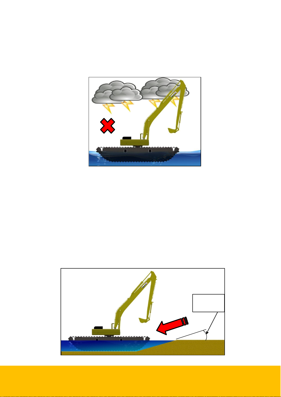
1. Work on wet ground, marshland, and shallow water.
2. The machine can travel and work in water not deeper than 2 meters, and work normally
under the following conditions:
a) The water flow speed: is 24 m/min (1.31 feet/second) or less.
b) The wave height: is 0.1m (3.93 in) or less.
c) The wind speed: is 240 m/min (8.94 mph) or less.
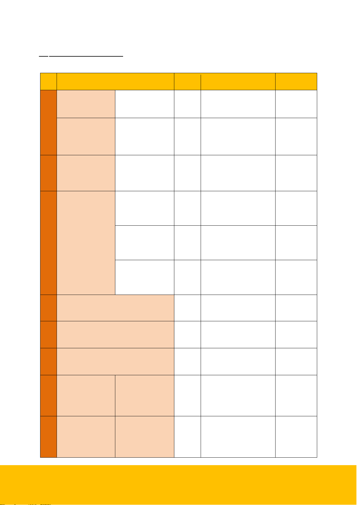
1.2.2 NON-ALLOWED CONDITIONS
1. Do not operate the machine on stumps, hard stones, or uneven ground that is frozen
and solid, when mounted with additional pontoons.
2. Do not attempt to operate the excavator when completely floating in water.
3. Do not travel over water of an unknown depth.
4. Do not use a bucket larger than the designated one. Otherwise, it will affect the stability
of the machine. The machine is only used for light loads and shouldn't be used for heavy
loads.
2.0 STRUCTURE
The AT300-V2/AT300PS-V2 hydraulic amphibious excavator has four traveling devices (two
traveling motors per amphibious undercarriage). Figure 2.0 shows a simple drawing of the
structure of the machine.