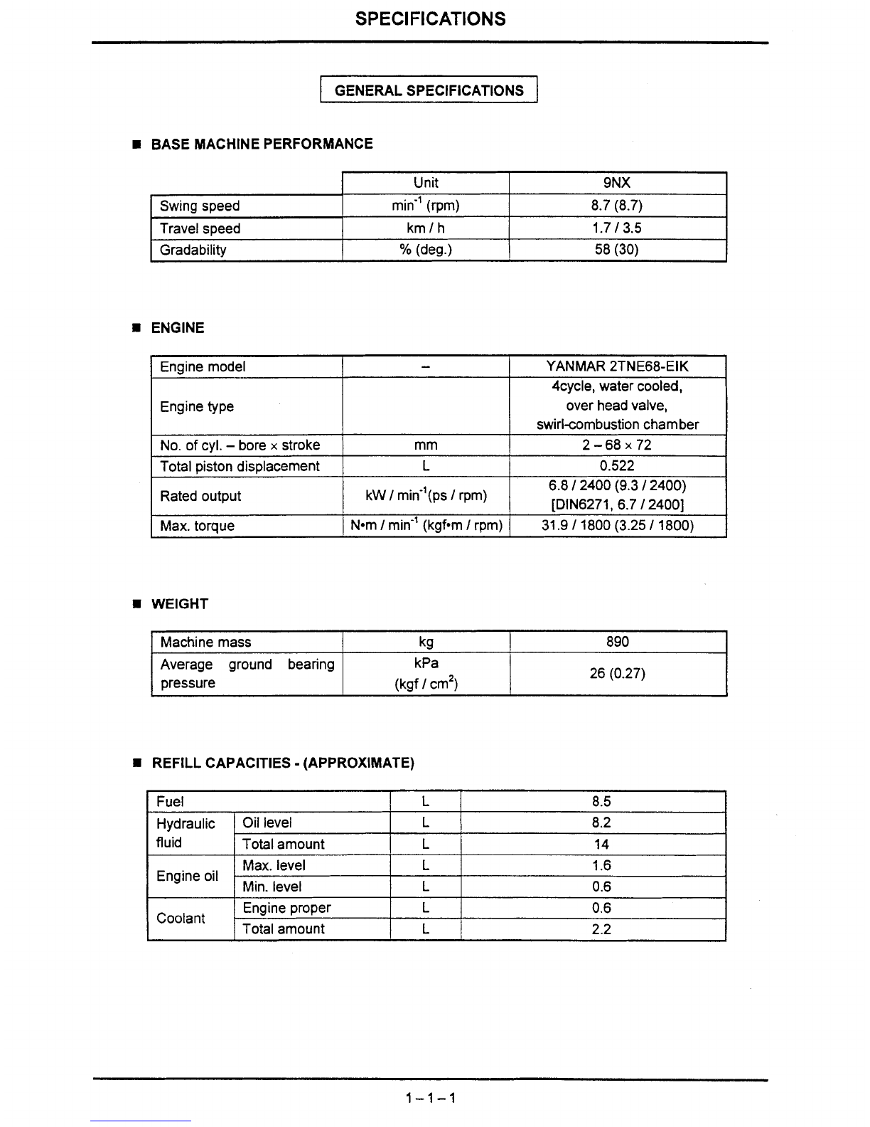
IHI 9NX User manual

Service
Guide
for
SERIAL NUMBERS:
BB000011
and
up
IHI
IHI
Construction Machinery Limited
PUB.
No.1
0404

HYDRAULIC MINI EXCAVATOR
-
TABLE OF CONTENTS
-
SECTION
1
..............................
SPECIFICATIONS
SECTION 2
..............................
STRUCTURE AND FUNCTION
SECTION
3
..............................
OPERATION
SECTION
4
..............................
MAINTENANCE
SECTION
6
..............................
PERFORMANCE STANDARDS

SECTION
I
SPECIFICATIONS
TABLE OFCONTENTS
Subject Page
.
.
.................................................................................................
Generalspecifications
1
1 1
.
.....................................................................
Overalldimensionsandworking ranges
1
-2
1
.
.
.......................................................................
Ratedobject handlingcapacitiestable
1
3
1
Weight breakdown
.................................................................................................
1
-4-
1
.
.
..........................................................................
Enginemaindate and specifications
1
5
1
Liftingcapacities
......................................................................................................
1
-6-
1

SPECIFICATIONS
GENERALSPECIFICATIONS
H
BASE MACHINEPERFORMANCE
H
ENGINE
Swing speed
Travelspeed
Gradability
H
WEIGHT
Unit
min" (rpm)
km/h
%
(deg.)
9NX
8.7 (8.7)
1.7
/
3.5
58 (30)
YANMAR 2TNE68-EIK
-
4cycle, water cooled,
over headvalve,
swirlcombustion chamber
2-68x72
0.522
6.8
/
2400 (9.3
/
2400)
[DIN6271, 6.7
1
24001
31.9
/
1800(3.25
/
1800)
Engine model
Enginetype
No. of cyl.
-
bore
x
stroke
Total pistondisplacement
Ratedoutput
Max.torque
-
mm
L
kW
/
min-'(ps
/
rpm)
N-m
/
min-' (kgfom
I
rpm)
Machine mass
H
REFILLCAPACITIES
-
(APPROXIMATE)
Average ground bearing
pressure
I
Fuel
L
8.5
I
I
kg 890
kPa
(kgf
/
cm2) 26 (0.27)
Hydraulic
I
fluid
I
Engineoil
Oil level
Total amount
Coolant
Max. level
.
Min. level
L
L
Engine proper
Total amount
8.2
14
L
L
1.6
0.6
L
L
0.6
2.2

SPECIFICATIONS
BUCKET
[ApplicableMachine]
@:
Std. applicable
0:
Applicable
x
:
Not applicable
Bucketcapacity
ISO
(m3)
Side
width
(mm)
370
320
220
Weight
(kg)
17.6
16.0
13.0
Heaped
0.022
0.017
0.011
Remarks
Standard
OPT'
OPT.
Number
of
teeth
4
3
2
Struck
0.015
0.013
0.008
1
Remarks
Generaldigging
Longarm
Ditchdigging
Ditchdigging
Combinations
Std.
arm
@
0
0
Long
arm
X
@
0

SPECIFICATIONS
OVERALL DIMENSIONS
1.
OVERALL DIMENSIONS
b.
I
t
'1
Unit: mm
D
E
F
G
H
@
R1105
Frontend
min
radius
(at
left
boom
swing)
STD
180
1220
700
-
950
Codes
A
B
C
I
J
K
L
M
N
0
R950
Frontend
rninradius
(at
right
boom
swing)
Description
Crawler shoewidth
Overalllengthof crawler
Overallwidth of crawler
Width
Height
Rear end swing radius
Rear end ground clearance
Mini.ground clearance
720
1405
485
405
160
Overalllengthof undercarriage
Blade height
Bladewidth
Overalllength Bladeinfront
Blade in rear
Frontend mini. radius at center
Arm headclearance
1500
240
700
2700
2980
1220
2180

SPECIFICATIONS
WORKING RANGE (BACK HOE)
I
A
I
Max. diaaina radius
I
2980
I
3190
I
Unit: mm
I
B
I
Max. bucket outreach at around level
I
2880
I
3100
I
I
C
I
Max. digging depth (Not used blade) 1570 1770
Key Std. arm
0.022
Description
Std. of bucketcapacity (m3),
IS0Heaped Long arm
0.017
D
E
F
G
H
I
J
K
L
M
N
Radiusof max. diggingdepth
Max. digging height
Radiusof max. digging height
Max. dumping height
Radiusof max. digging height
Min. dumping height
Radiusof min. dumpingheight
Max. vertical digging depth
Radiusof max. vertical digging depth
Radiusof min. digging ground level
Max. clean-upradius at floor level
1330
2755
1740
1340
2950
1820
1970
1590
850
1120
1175
2160
1040
2290
2150
1700
660
1220
1400
2140
990
2500

SPECIFICATIONS
WEIGHT BREAKDOWN
1. Totaloperating weight
2.
Basemachine
ShoelCabinSpec.
Rubbershoe
1
Rubbzy;E;bin Spec.
I
Weight (kg)
785
Weight (kg)
890
Thisweight isnotthemassofthe machine
body.
It
includestheweight of water, fuel,
bladeand others.
3.
Upper structure
I
Specification
1
Weight (kg)
4. Under carriage
5.
Hoeattachment
I
Specification
I
Weight (kg)
Specification
Rubbershoe Weight (kg)
340
Standardarm
Longarm 105
105

SPECIFICATIONS
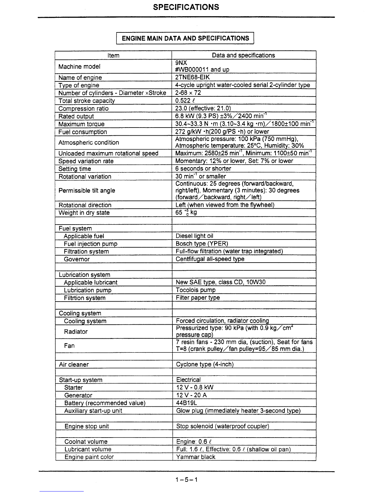
ENGINE MAIN DATA AND SPECIFICATIONS
ltem
Machine model
Name of engine
Type of engine
Number of cylinders
-
Diameter xStroke
Total stroke capacity
Compression ratio
Ratedoutput
Maximumtorque
Fuelconsumption
Atmospheric condition
Unloadedmaximum rotationalspeed
Speed variation rate
Settingtime
Rotationalvariation
Permissibletilt angle
Rotationaldirection
Weight in
dry
state
Fuelsystem
Applicable fuel
Fuel injection pump
Filtrationsystem
Governor
Lubricationsystem
Applicable lubricant
Lubrication pump
Filtrtionsystem
Coolingsy&m
Cooling system
Radiator
Fan
Air cleaner
Start-up system
Starter
Generator
Battery (recommended value)
Auxiliary start-up unit
Enginestop unit
Coolnat volume
Lubricantvolume
Enginepaint color
Dataand specifications
9NX
#WB000011and up
2TNE68-EIK
4-cycle uprightwater-cooledserial 2-cylinder type
2-68
x
72
0.522
!
23.0 (effective:21.O)
6.8 kW (9.3 PS) st3%/2400 min-'
30.4-33.3 N .m (3.10-3.4 kg .m)/1800+100 min-'
272 g/kW ~h(200g1PS ah) or lower
Atmospheric pressure: 100kPa (750 mmHg),
Atmospherictemperature: 25"C, Humidity: 30%
Maximum: 2580k25min", Minimum: 1100+50 min-'
Momentary: 12%or lower, Set: 7% or lower
6 seconds or shorter
30 min-' or smaller
Continuous:25 degrees (forwardlbackward,
rightlleft), Momentary(3 minutes): 30 degrees
(forward/backward, right/left)
Left(when viewed from the flywheel)
65
':
kg
Diesellight oil
Boschtype (YPER)
Full-flow filtration (watertrap integrated)
Centfifugalall-speedtype
New SAEtype, class
CD,
10W30
Tocolois pump
Filterpapertype
Forcedcirculation, radiatorcooling
Pressurizedtype: 90 kPa (with 0.9 kg/cmL
pressurecap)
7 resin fans
-
230 mm dia, (suction), Seat for fans
T=8 (crank pulley/fan pulley=95/85 mmdia.)
Cyclonetype (4-inch)
Electrical
12V-0.8 kW
12V-20A
44B19L
Glow plug (immediately heater 3-second type)
Stop solenoid (waterproof coupler)
Engine: 0.6
E
Full: 1.6
E,
Effective: 0.6
!
(shallowoil pan)
~
~-
Yammar black

SPECIFICATIONS
LIFTING CAPACITIES 9NX
LOAD RATING CHART (SAE
METHOD)
Note
:
At front over end and the Blade fulcrum with equipped standard arm.
Rated loads do not exceed
87%
of hydraulic capacity or
75%
stability.
4
3
2
1
0
(rn)
Lifting Radius (R
m)
Unit
:
ton Position of
normal lifting(+)
,
j
Position of
max. lifting
(*)
+
:
lifting height
*
:
Maximum lifting radius

SPECIFICATIONS
LOAD RATINGCHART (SAE METHOD)
Note
:
At front over end and the Bladefulcrumwith equippedstandard arm.
Rated loads do not exceed
87%
of hydraulic capacity or
75%
stability.
Position of
max. lifting
(Sr)
(m)
3
2
1
E
E.
E
cn
-
5
0
C
-
a5
3
-
1
-2
Lifting
Radius
(R
m)
(m)
Unit
:
ton
Positionof
+
:
lifting
height
normallifting(+)
radius
L
*
:
Maximumlifting
I
Multiply lifting
4
capacity by
220
to get figure in lbs.
0.1
1
v
1
I
0.13
-t-
0.1 6
016
T
0.09 0.10 0.16
x
+
t+
+
0.15 0.18
0.10
--
3
2
1
0
0.08
w,
I
11
0.09 0.10 0.1
I
I'
5 0.23 0.25
+
+
+
+
0.08 0.10 0.14 0.20
I
II
I
T
0.08 0.09 0.13 0.21 028
+
I
+
0.10 0.13 0.21
I
1
+
0.14 0.21

SECTION
2
STRUCTURE FUNCTION
TABLE OF CONTENTS
Subject Page
.
.
Nomenclature
.....................................................................................................
2
1 1
Common models of main components
..................................................................
-
Hydraulicsystem diagram
......................................................................................2-3-
1
......................................................................................
Hydraulicsystem diagram
2
-4
-
1
Hydraulicsystem
....................................................................................................
-
Locationof engine installedparts
...........................................................................2
-6-
1
Hydraulictank ass'y
...............................................................................................
2
-7-
1
Pumpdrive device
.................................................................................................
2
-
8
-
1
Hydraulicpump
......................................................................................................
2
-
9
-
1
Controlvalve ass'y
................................................................................................. 2
-
1
0
-
1
Swing drive device
&
bearing
.................................................................................
2
-
1
1
-
1
Swing motorass'y
................................................................................................
2
-
12
-
1
Rotaryjoint ass'y
..................................................................................................
2
-
1
3
-
1
Travel motor and reductiongear
..........................................................................
2
-
1
4
-
1
...............................................................................
Crawler shoe adjustingdevice
2-
15
-
1
Frong idler ass'y
..................................................................................................
2
-
1
6
-
1
...................................................................................................
Lower roller ass'y
2
-
1
7
-
1
Upper roller ass'y
...................................................................................................
-
.....................................................................................
Rubbercrawler shoe ass'y
2
-
1
9
-
1
Remotecontrolvalve
-
Blockvalve ass'y
....................................................................................................
-
Travel speed shift valve ass'y
................................................................................
2
-
22
-
1
Hydrauliccylinders
............................................................................................... 2
-2
3
-
1
Attachmentass'y
...................................................................................................
2
-
2
4
-
1
Bucket ass'y
.........................................................................................................
2
-
2
5
-
1
Attachmentdate
....................................................................................................
2
-
2
6
-
1
OK
monitorass'y
....................................................................................................
-
Electricalwiring and locations
................................................................................
2
-
2
8
-
1
Electricalwiring systemdiagram
...........................................................................
2
-
2
9
-
1

SPECIFICATIONS
NOMENCLATURE
Typical Example
(1) Bucket
(2) Bucket Link
(3)Arm Link
(4)Tooth
(5) Bucket Cylinder
(6)Arm
(7) Boom
(8) Arm Cylinder
(9) Boom Cylinder
(10) Control Valve
(11) Operator's Seat
(12) Swing Drive (with motor)
(13) Sprocket
(14) Travel Drive(with motor)
(15) Swing Bearing
(16) Track Roller
(17) Spanner Cylinder
(18) Guide Plate
(1
9)
Track Adjuster
(20) Front Idler
(21) Blade Cylinder
(22) blade
(23) Track Shoe
(24)Air Cleaner
(25) Muffler
(26) Rotaryjoint
(27) Engine
(28) Radiator
(29) Battery
(30) HydraulicPump
(31) FuelTank
(32)
Boom Swing Cylinder
(33) Return Filter
(34) Hydraulictank

SPECIFICATIONS
9NX
HYDRAULICSYSTEM DIAGRAM
Arm
Swing T Blade Spanner Tr
I
Main pump
Tank level capacity
:
8.2
L
suction
Total svstem volume
:
14
L
strainer
Relief valve set pressure
Pump
flow
rate (Max.):
P1
;
11.
Umin
P2
;
11.1
Umin
The service ports use the
flow
shared
by
the
P1
and
P2
pumps.

STRUCTURE
8
FUNCTION
9

SPECIFICATIONS
9NX
I
ENGINEAND AUXILIARY COMPONENTS
1
(enginecomponentnames, layout)
Oil
supply
port
Oil
filter
--
/:'
Oil drain plug
mm
dia..

SPECIFICATIONS
HYDRAULICTANK ASS'Y
Layout
Oil supply plug
Hydraulicoil tank
Returnfilter
(cartridge type)
0
ring
Drain plug Disassemblydrawing
\
'Strainer
o
ring
\
Suction strainer
Oil levelgauge
Bolt
'
cover
Maintenance Intervals (Every Hours)
--
Contents Initial After Brekeworks
Suction strainer Cleaning
-
1,000 500
P
Return filter Replace
50 500 100
Specifield strainer
IS-SUPER A
Genuine hydraulicoil
(wear-resistance
hydraulic oil)
Fluid Volume
(e)
Tank level
8.2
Replace Intervals
Total system
14
General
operation
1,000
Breakerworks
500

SPECIFICATIONS
9NX
Layout
Spring pin
Disassemblvdrawina
Treatmentbolt
(M10
x
25)
Notes:
1.
If the casing is empty and free from oil
due to pump exchange, etc., be sure to
supply clean hydraulic oil from the oil
supply port beforestart-up.
2.
Tighten hexagonal socket headed bolt
(3)
with the specified tightening torque
of
48
to
53
N-m.
3.
Before assembling the pump, coat the
Never-Seize (special grease) on the
spline and fill the space with it.
Assembly drawing (crosssection)
@
@
Treatment bolt
Treatment
(MI0
x
25)
L
J
washer

SPECIFICATIONS
9NX
HYDRAULIC PUMP
v~eliver~
port
PF3/8
Logicaldelivery volume
:
No.1 pump 4.64 cm3
No.2pump 4.64 cm3
Rated pressure
:
18.6
MPa
(190
kgf/cm2)

Reliefvalve assembly drawing cross sedion
MPa (kgf/cm2) MPa (kgf/cmz)
No.
1
2
3
4
STRUCTURE
8
FUNCTION
9NY
MR2
Maln
reliefvalve
5-1
-
-
6
Adjustment valve
1.
7 Adjustmentspring
1
8
Nut
1
9
Adjustmentvalve spring
1
10 Super pressurevalve spring 1
11
O-ring 1
12 O-ring
1
13 O-ring
2
14 Backupring
2
15 O-ring 1
Description
Socket
Super pressurevalve
Piston
Adjustmentsection body
Upon assemblingthe
valve block
Q'ty
1
1
1
1
CONTROLVALVE
(1)
0783 767 UA
OR1
Boom up MR1
Overload Main
reliefvalve relief valve
Notes on damages due to over-tightening
0
Pipingadapter on PIT
port
marked
%
Tighteningtorque:
69aN
.
m (7ilkgf. m)-
0
Other pipingadapters
Tighteningtorque: 344N
.
m (3.5-4.5kgf. m)
Table of contents
Other IHI Excavator manuals
Popular Excavator manuals by other brands

Schaeff
Schaeff HT 12 manual

jcb
jcb 8025 ZTS Operator's manual

achilles
achilles Kubota A15S Owner's handbook

Worldwide Construction And Forestry Division
Worldwide Construction And Forestry Division 27C ZTS Technical manual

Komatsu
Komatsu PC200LL-7L Operation & maintenance manual

Komatsu
Komatsu PC750LC-7 Operation manual