HBM VK20A User manual

Mounting Instructions | Montageanleitung |
Notice de montage
English Deutsch Français
VK20A

Hottinger Baldwin Messtechnik GmbH
Im Tiefen See 45
D-64239 Darmstadt
Tel. +49 6151 803-0
Fax +49 6151 803-9100
www.hbm.com
Mat.: 7-2001.2335
DVS: A2335-2.0 HBM: public
08.2017
EHottinger Baldwin Messtechnik GmbH.
Subject to modifications.
All product descriptions are for general information only.
They are not to be understood as a guarantee of quality or
durability.
Änderungen vorbehalten.
Alle Angaben beschreiben unsere Produkte in allgemeiner
Form. Sie stellen keine Beschaffenheits- oder Haltbarkeits
garantie dar.
Sous réserve de modifications.
Les caractéristiques indiquées ne décrivent nos produits
que sous une forme générale. Elles n'impliquent aucune
garantie de qualité ou de durabilité.

Mounting Instructions | Montageanleitung |
Notice de montage
English Deutsch Français
VK20A

2A2335-2.0 HBM: public VK20A
English
1 Safety instructions 3........................................
2 Markings used 6............................................
2.1 The markings used in this document 6..........................
2.2 Symbols on the product 6.....................................
3 Application 8...............................................
4 Installation 9...............................................
4.1 Dimensions 9...............................................
4.2 Mechanical design 10.........................................
5 Electrical connection 11......................................
5.1 Connection cable for evaluation electronics 11....................
5.1.1 Mechanical connection of the connector cables 14................
5.1.2 Electrical connection of T20WN, T21WN (St1 and St2) 16..........
5.1.3 Electrical connection of T22 (St1 and St2) 17.....................
5.1.4 Electrical connection of the voltage supply (St7) 18................
5.1.5 Electrical connection of torque output Md [V] 19...................
5.1.6 Electrical connection of torque output Md [I] 19...................
5.1.7 Electrical connection of speed/angle of rotation output (n/) 20.......
5.1.8 Functional check 21...........................................
5.1.9 Control signal (T20WN, T21WN) 21.............................
6 Specifications 23............................................
7 Accessories 25..............................................

Safety instructions
VK20A A2335-2.0 HBM: public 3
1 Safety instructions
Appropriate use
To ensure safe operation, the junction box may only be
used as described in the mounting instructions. It is also
essential to follow the respective legal and safety regula
tions for the application concerned during use. The same
applies to the use of accessories.
The junction box is not a safety element in terms of
appropriate use. For correct and safe operation of this
junction box, it is essential to ensure appropriate trans
portation, storage, installation, and fitting and to operate
and maintain all equipment with care.
General dangers of failing to follow the safety
instructions
The junction box corresponds to the state of the art and
is safe to operate. If the junction box is used and oper
ated inappropriately by untrained personnel, residual
dangers may arise.
Everyone responsible for installing, starting up, maintain
ing or repairing the junction box needs to have read and
understood the operating manual and in particular the
safety instructions.
Residual dangers
The scope of performance and supply of the junction box
covers only part of the connection technique. In addition,
equipment planners, installers and operators should plan,
implement and respond to the safety engineering consid
erations of the connection technique in such a way as to
minimize residual dangers. Prevailing regulations must
be complied with at all times. Residual dangers con

Safety instructions
4A2335-2.0 HBM: public VK20A
nected with the connection technique need to be pointed
out.
Qualified personnel
The junction box may be used by qualified personnel
only, the specifications and the special safety require
ments and regulations need to be followed in all cases. It
is also essential to observe the appropriate legal and
safety regulations for the application concerned during
use. The same applies to the use of accessories.
Qualified personnel means. personnel familiar with the
installation, fitting, starting up, and operation of the prod
uct and trained according to their job.
Conditions on site
Protect the junction box from dirt and humidity.
Maintenance
The junction box provides IP65 protection (protection
against dust and water jets). Make regular checks to
ensure the tightness and efficiency of the rubber lid seal
and the screw fittings.
Prevention of accidents
The prevailing accident prevention regulations must be
observed.
Unauthorized conversions and modifications are
prohibited
HBM's express consent is required for modifications
affecting the equipment's design and safety. HBM does
not take responsibility for damage resulting from unau
thorized modifications.

Safety instructions
VK20A A2335-2.0 HBM: public 5
It is strictly forbidden to carry out any repairs and solder
ing work on the motherboards or to replace any compo
nents. Repairs may only be carried out by persons autho
rized by HBM.
SDuring installation and when connecting the cables,
take action to prevent electrostatic discharge as this
may damage the connected electronics.
SWhen connecting additional devices, comply with the
safety requirements for electrical measurement, con
trol, regulatory and laboratory equipment (EN 61010).
SAll the interconnecting cables must be shielded
cables. The shield must be connected extensively to
ground on both sides.

Markings used
6A2335-2.0 HBM: public VK20A
2 Markings used
2.1 The markings used in this document
Important instructions for your safety are specifically
identified. It is essential to follow these instructions in
order to prevent accidents and damage to property.
Symbol Significance
CAUTION This marking warns of a potentially dangerous
situation in which failure to comply with safety
requirements can result in slight or moderate physical
injury.
Notice This marking draws your attention to a situation in
which failure to comply with safety requirements can
lead to damage to property.
Emphasis
See….
Italics are used to emphasize and highlight text and
references to other chapters and external documents.
2.2 Symbols on the product
CE mark
The CE mark enables the manufacturer to guarantee that
the product complies with the requirements of the rele
vant EC directives (the declaration of conformity is avail
able at http://www.hbm.com/HBMdoc).
Statutory marking requirements for waste disposal
National and local regulations regarding the protection of
the environment and recycling of raw materials require
old equipment to be separated from regular domestic
waste for disposal.

Markings used
VK20A A2335-2.0 HBM: public 7
For more detailed information on disposal, please contact
the local authorities or the dealer from whom you pur
chased the product.

Application
8A2335-2.0 HBM: public VK20A
3 Application
The VK20A junction box enables T20WN, T21WN and
T22 torque transducers to be connected to HBM mea
surement electronics. If the measurement electronics do
not feed supply voltage, the junction box needs to be
powered by a 24 V power source (14 V...30 V) to St7.

Installation
VK20A A2335-2.0 HBM: public 9
4 Installation
4.1 Dimensions
138
150
approx. 25
23.5
53
6
Ø 4.4
40
18.25
A
23.5
View A
65
18.25
53.5
approx. 25
Dimensions (in mm;
1 mm = 0.03937 inches)
Fig. 4.1 Dimensions
Installation
10 A2335-2.0 HBM: public VK20A
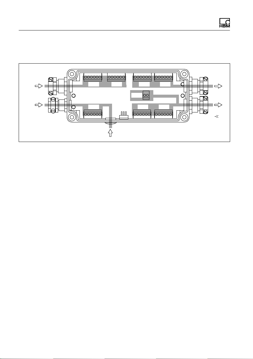
4.2 Mechanical design
St1 St2 St3 St4
St7 St6 St5
16161616
616161
Md [V]
n
External control signal
T20WN
T21WN
T22
Supply
voltage
St8 Md [I])
Fig. 4.2 Connection clamps in the opened VK20A junction
box

Electrical connection
VK20A A2335-2.0 HBM: public 11
5 Electrical connection
5.1 Connection cable for evaluation
electronics
HBM provides the following connector cables for con
necting the T20WN, T21WN and T22 through the VK20
junction box to the evaluation electronics:
S1-Kab 151-1.5 (15‐pin D‐sub connector (male) - free
ends)
S1-Kab 152-1.5 (SUBCON5 - free ends)
YE/RD
1
2
3
4
5
6
7
8
9
10
11
12
13
14
15
YE
BK
BU
BN/BU
WH
PK
GY/PK
GY
GN
BN
RD
1-Kab151-1.5 1-Kab152-1.5
1
2
3
4
5
bared
BK
BU
WH
RD
GN
Shield
Fig. 5.1 Cable for connecting to the evaluation electronics
Electrical connection
12 A2335-2.0 HBM: public VK20A
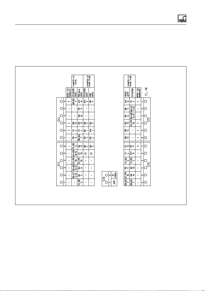
The cable configuration is adjusted to the system device
to be connected. In the junction box housing, there is an
instruction leaflet with the connection diagram for the var
ious HBM system devices (see both parts of Fig. 5.2).
Md [V]
Md [I]
Continuationof the figure on next page

Electrical connection
VK20A A2335-2.0 HBM: public 13
T20WN
T21WN
T22
Fig. 5.2 Connection diagram for the various HBM system
devices

Electrical connection
14 A2335-2.0 HBM: public VK20A
5.1.1 Mechanical connection of the connector
cables
The junction box includes a set of cable sleeves,
intended for bushing the transducer connection cable, the
voltage supply and the Md/n outputs. The side hole for
the external control signal is closed with a screw for
delivery. If need be, use a suitable PG7 screwed joint
with an anti‐buckling socket.
Anti‐buckling socket,
internal Ø 7 mm
Clamping ring
T20WN, T21WN, T22
Power
Cable shield
looped round
clamping ring
Anti‐buckling
socket, internal
Ø 5 mm
Cable sleeve
Rubber seal Wall of the housing
Fig. 5.3 Cable bushing ”T20WN, T21WN, T22” and
”POWER” at the junction box
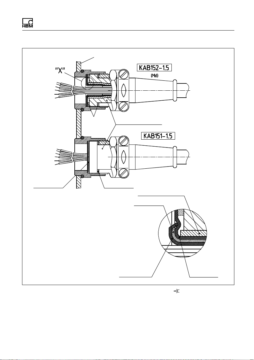
Electrical connection
VK20A A2335-2.0 HBM: public 15
Wall of the housing
Clamping ring Anti‐buckling socket,
internal Ø 8.5 mm
Cable shield
looped round
clamping ring Clamping ring
Outer sheath of cable
Earth sleeve
Stranded filler wire
of the internal
cable shields Cable shield
Detail X
Fig. 5.4 Cable bushing ”Md” and ”n/ ” at the junction box

Electrical connection
16 A2335-2.0 HBM: public VK20A
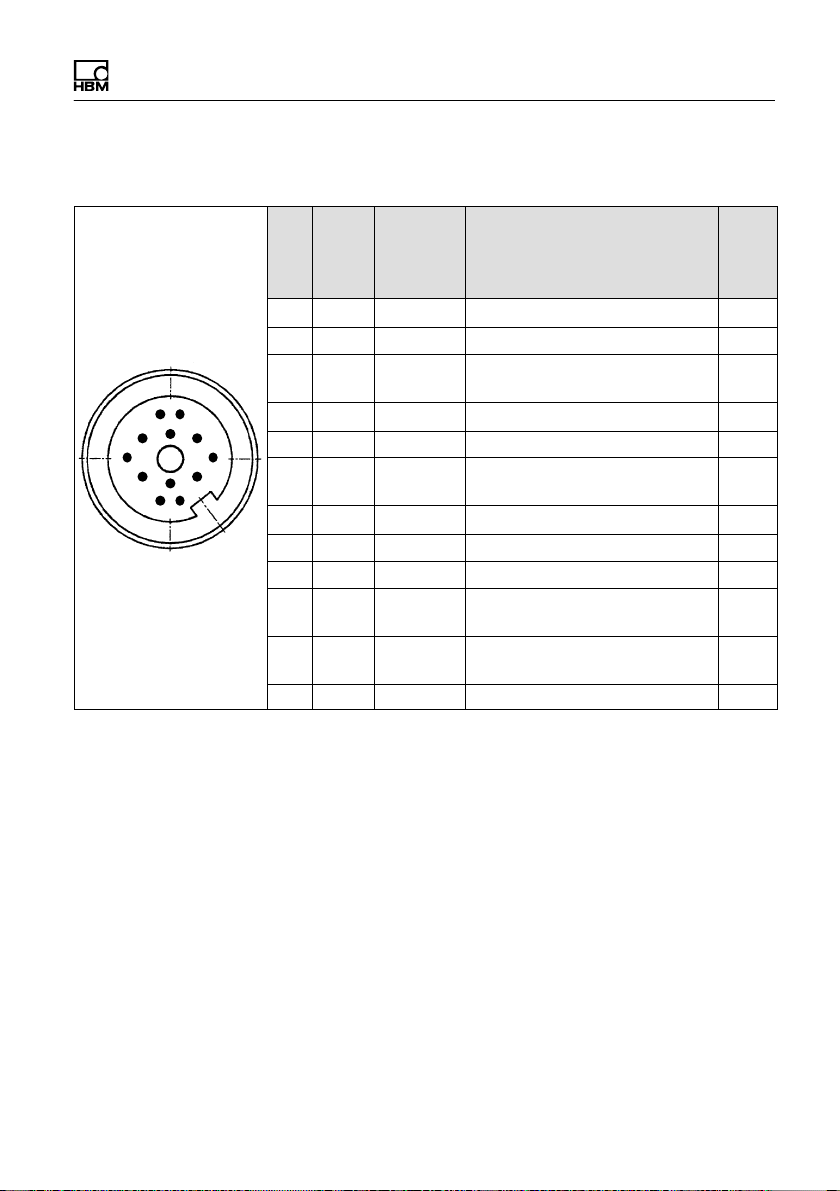
5.1.2 Electrical connection of T20WN, T21WN (St1
and St2)
A
B
C
D
E
F
G
J
H
L
M
K
Pin Wire
color
Strip
terminal/
terminal
VK20A
Function I/O1)
A BK St1/1 None -
B RD St2/1 Measurement signal: speed/
angle of rotation
I
C BN St1/3 Measurement signal: torque
±10 V
I
D WH St1/4 0 V; I
E YE St1/5 Supply voltage 0 V O
F VT St1/6 Supply voltage 12 V O
G GN St1/2 Measurement signal: speed/
angle of rotation (90°phase
shifted)
I
H PK St2/2 None -
J GY St2/3 None -
K GY/
PK
St2/4 Trigger control signal O
L BU/
RD
St2/5 None -
M BU St2/6 Cable shielding -
Tab. 5.1 Transducer connection T20WN, T21WN
1) O=Output; I=Input
Electrical connection
VK20A A2335-2.0 HBM: public 17
5.1.3 Electrical connection of T22 (St1 and St2)
A
B
C
D
E
F
G
J
H
L
M
K
Pin Wire
color
Strip
terminal/
terminal
VK20A
Function I/O1)
A BK St1/1 None -
B RD St2/1 None -
C BN St1/3 Measurement signal:
torque"5V
I
D WH St1/4 Ground (torque) I
E YE St1/5 Ground (supply) O
F VT St1/6 Supply voltage
+11.5 V … 30 V
O
G GN St1/2 None -
H PK St2/2 None -
J GY St2/3 None -
K GY/
PK
St2/4 None -
L BU/
RD
St2/5 Measurement signal: torque
10"8 mA I
M BU St2/6 Cable shielding -
Tab. 5.2 Connection T22
1) O=Output; I=Input
Electrical connection
18 A2335-2.0 HBM: public VK20A
5.1.4 Electrical connection of the voltage supply
(St7)
Strip terminal/
terminal
Function I/O1)
St7 /1 0 V; 2) O
/2 control signal (external trigger 0 V; ) I
/3 control signal (external trigger 5 V … 30 V) I
/4 24 V3) O
/5 Supply voltage VK20 24 V (14 … 30 V)4) I
/6 Supply voltage 0 V; I
Tab. 5.3 Connector pin assignment St7
1) O=Output; I=Input
2) Linked internally with St7/Pin6. Can be bridged with St7/Pin2 if necessary.
3) Linked internally with St7/Pin5. Can be used for triggering the control signal if necessary.
4) In conjunction with MGCplus through St3/1.
Other manuals for VK20A
1
Table of contents
Languages:


