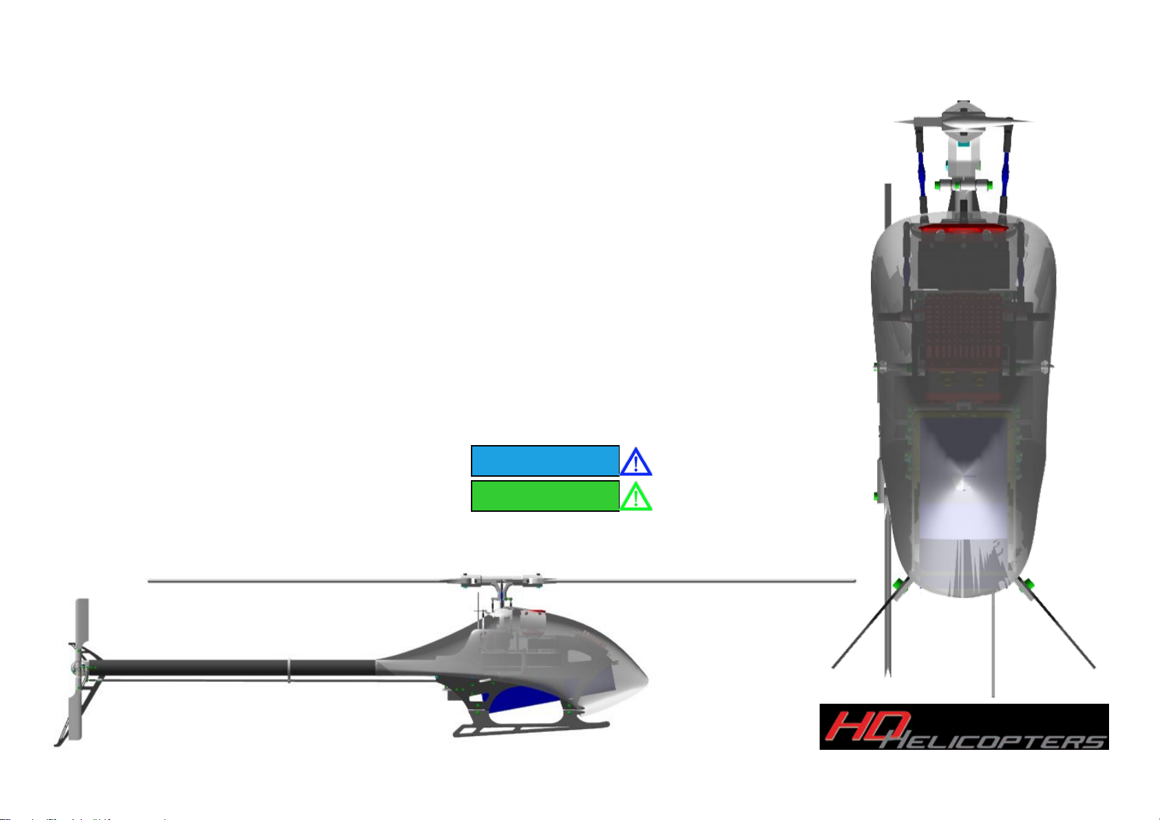
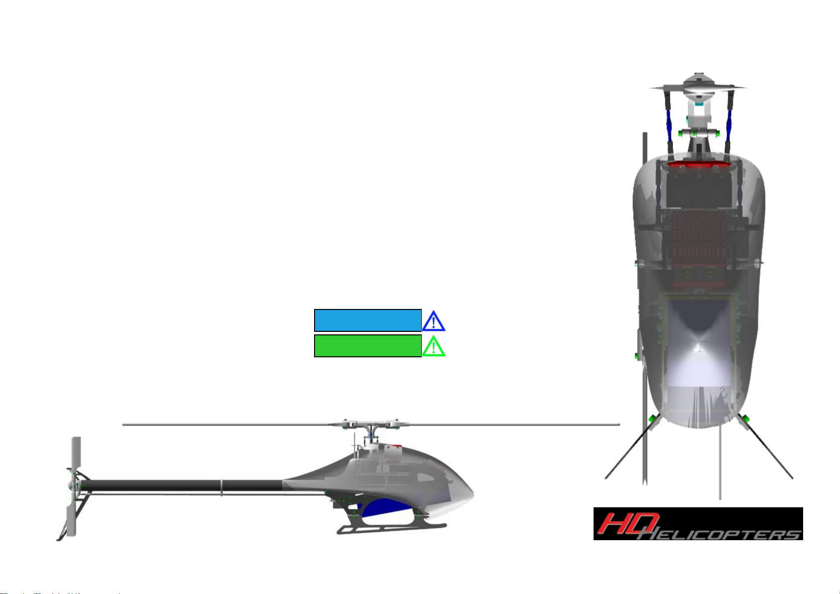
HD Helicopters HD 750 CELL DBDS User manual

PLEASE CAREFULLY READ AND UNDERSTAND THESE INSTRUCTIONS BEFORE ASSEMBLY
Copyright 2016. All rights reserved by HD-Helicopters GmbH.
www.hd-helicopters.com
HD 750 CELL DBDS Assembly Manual V1

Damit Sie Ihren HD 750 Helikopter korrekt zusammenbauen und sicher betreiben können, verwenden wir in der Anleitung dieses Symbol an Stellen, an denen besondere Aufmerksamkeit benötigt wird. Sollten
diese besonderen Hinweise beim
Zusammenbau nicht genau beachtet werden, können elektronische und mechanische Schäden oder sogar Verletzungen nicht ausgeschlossen werden.
Verwendungshinweise:
Diese Anleitung beinhaltet detaillierte Anweisungen, um den HD 750 CELL DBDS korrekt aufzubauen und einzustellen. Bitte folgen Sie den Instruktionen genau, um die bestmögliche Performance und mechanische
Exaktheit des fertigen Modelles zu erhalten. Für die erfahrenen Modellhelikopterpiloten empfehlen wir ausdrücklich, sich genau an die Schritte und Hinweise in der Anleitung zu halten, um das bestmögliche Endresul-
tat zu bekommen. Bitte bewahren Sie diese Anleitung gut auf und ziehen sie diese zu Rate, wenn Sie Teile austauschen oder ein Upgrade vornehmen.
Haftungsverzicht
Trotz größter Sorgfalt bei der Erstellung dieser Anleitung kann der Hersteller und Großhändler keine Garantie für das notwendige und korrekte Verständnis der beschriebenen Schritte beim Zusammenbau überneh-
men und lehnt somit jegliche Haftung und Ersatzansprüche ab, die aus dem missbräuchlichen Verwenden des Modellhelikopters entstanden oder abzuleiten sind.
Dieses Modell wurde für versierte und erfahrene Piloten entwickelt. Wenn Sie einem erfahrenen Piloten beim Betreiben seines Modelles zuschauen, vermag der Flug auf den ersten Blick einfach aussehen. Bedenken
Sie aber, dass sehr viel Übung und unzählige Stunden notwendig sind, um dieses Modell sicher zu betreiben.
Besonders Neueinsteiger oder weniger erfahrene Kunden des HD 750 CELL DBDS empfehlen wir, sich versierten Modellhelikopter Piloten anzuschließen um Unterstützung für die ersten sicheren Flüge zu erhalten.
wir empfehlen Ihnen, regelmäßig zu üben um einen sicheren Umgang des Modelles zu gewährleisten und das RC Helikopter-Hobby genießen zu können.
SICHERHEITSHINWEIS
LiPo Batterien benötigen besondere Aufmerksamkeit und Pflege! Unsachgemäße Lagerung, falsches Aufladen oder nicht korrekte Handhabung können Brände verursachen und den RC Helikopter beschädigen oder
gar ganz zerstören. Auch Verletzungen können nicht ausgeschlossen werden. Für weitere Informationen kontaktieren Sie bitte Ihren Modellbauhändler oder den Hersteller.
1. Bitte prüfen Sie unbedingt die Einstellungen an Ihrem Ladegerät und stellen Sie sicher, dass sie den Spezifikationen des Akkus entsprechen.
2. Für den Fall, dass LiPo Akkus in einem Metallbehälter oder feuersicheren Behältnis untergebracht sind, welche luftdicht verschlossen sind, kann nicht ausgeschlossen werden, dass die Batterien in Brand
geraten, da die austretenden Gase nicht entweichen können. Wir empfehlen, LiPo Akkus in einem nicht luftdicht versiegelten und speziellen LiPo-Beutel oder feuersicheren Behältnis aufzubewahren, um
diese über einen längeren Zeitpunkt zu lagern.
3. Bitte halten Sie LiPo Akkus von Wärmequellen fern.
4. LiPo Akkus niemals im voll geladenen Zustand lagern. Beachten Sie eventuelle Lagerungsprogramme (Storage-Ladung) Ihres Ladegerätes.
5. Die Plus- und Minus Leitungen der LiPo Akkus NIEMALS KURZ SCHLIEßEN
6. Bevor Sie den LiPo Akku mit dem Regler des Helikopters verbinden, stellen Sie sicher, dass der Sender eingeschaltet ist und sich alle Knüppel und Schalter in den sicheren Stellungen befinden.
VERMEIDUNG LOSER SCHRAUBEN UND MUTTERN
Es ist zweitrangig, wie fest Schrauben, Muttern oder Bolzen festgezogen sind, sie werden sich wegen der Vibrationen des Helikopters mit der Zeit lösen. Sollte dies während des Fluges geschehen, könnten Sie die
Kontrolle über Ihren RC Helikopter verlieren und sich bzw. Andere in eine eventuell gefährliche Situation bringen.
Deshalb empfehlen wir DRINGEND, Schrauben, Muttern oder Bolzen mit Schraubensicherungslack zu sichern. Es gibt grundsätzlich 2 unterschiedliche Arten, blau (mittelfest) sowie rot (endfest).
• Reinigen Sie die Schraube, Mutter oder den Bolzen mit Alkohol oder Nitro-Verdünnung BEVOR Sie Schraubensicherungslack verwenden.
• Benutzen Sie blauen Sicherungslack für Schrauben, die Sie später wieder lösen möchten/müssen.
• Roten Sicherungslack für Schrauben, die permanent gesichert sein sollen/müssen.
1. CA - An dieser Stelle bitte Sekundenkleber verwenden
2. LOCTITE 243 - LOCTITE 648 Zuerst die Schraube(n) von Öl- und Fettrückständen befreien, dann den entsprechenden Sicherungslack verwenden.
3. FETTEN; Bitte diese Teile fetten
Copyright 2016 All rights reserved by HD-Helicopters. www.hd-helicopters.com Page 1
HD 750 Cell DBDS Assembly Manual
HD 750 Cell DBDS Assembly Manual
Benötigte Werkzeuge zum Aufbau
Benötigte Komponenten, um den HD750 flugfertig aufzubauen
- CCPM, PCM oder 2,4 Ghz Funkfernsteuerung mit 3 x standard-Servo und 1 x Standard oder Midi Heck-Servo
- 3 Achsen Flybarless-System
- KONTRONIK Pyro 700-45 to 850-40 Brushless Außenläufer-Motor (falls nicht im Set enthalten)
- LiPo Pack 12S to 14S -3700 bis zu 5000 mAh (je nach Set-Up)
- 120A to 200A Regler
- CF FBL Hauptrotorblätter 690mm - 750mm (falls nicht im Set enthalten)
- LiPo Ladegerät
Benötigte Werkzeuge (nicht enthalten)
- Sechskant-Inbus Werkzeug der Größen 1,5 mm - 2 mm - 2,5 mm - 3 mm - 4 mm - 5 mm
- Kreuz-Schlitz Werkzeug in den Größen Groß- Mittel - Klein
- Nuss-Schraubendreher 4,5 mm - 5,5 mm - 7 mm
- Messer
- Universalzange
- Schere
- Schleifpapier
- Kugelkopfzange
- Maßband
- Digitale Pitch-Lehre
- Sekundenkleber
- Epoxy 10 Min.
- Fett
Loctite 243 –648
Copyright 2016 All rights reserved by HD-Helicopters. www.hd-helicopters.com Page 2
Use Loctite 243
Use Loctite 648

HD 750 Cell DBDS Assembly Manual
For the correct assembly and safe flying of your HD750 Model, this manual uses this symbol where special attention is required. Failure to carry out the instructions at
this point in the assembly will result in an electronic and/or mechanical failure or possible injury.
HOW TO USE THIS INSTRUCTION MANUAL
This manual contains the detailed instructions to build and set up the HD750 CELL DBDS. Please follow it to ensure that you achieve the best performance and mechanical
integrity from your finished kit.
For those of you who already have experience with model helicopters, we strongly suggest that you assemble and adjust your model according to these instructions for the
best results. Please keep this manual in a safe place and refer to it when replacing spare parts or upgrading.
DISCLAIMER
While every effort has been made to supply the proper information in this manual, the Manufacturer and Distributor cannot guarantee that the consumer will interpret or fol-
low these instructions as intended and therefore the Manufacturer and Distributor cannot assume any liability for damage or claims occurring from the misuse of our product.
This product is intended for advanced users. It may look easy when watching an experienced pilot flying his model, but it takes dedication and numerous hours of practice to
be able to operate this model safely and efficiently.
Beginners are encouraged to seek help from an experienced pilot to assist in the first test flights. We encourage you to practice frequently and enjoy the experience of RC
rotary flight!
WARNING
LiPo batteries need special care. Improper storage, handling or charging may result in a fire, with resulting damage to your helicopter and possibly to yourself and your sur-
roundings. Contact your dealer or supplier for more information.
1. Check your charger settings before charging your LiPo battery to insure they are correct for the specifications of the battery.
2. We recommend using the original LiPo Sack (manufactured in the USA) since it was designed to contain the jet flames discharged from a failing LiPo battery.
3. Please keep LiPo Batteries away from sources of heat.
4. Never store LiPo Batteries fully charged.
5. NEVER SHORT OUT LiPo Battery wires.
6. Before connecting your LiPo battery to the Helicopter, make sure your transmitter is turned ON and all sticks and switches are set properly.
TO PREVENT LOOSE SCREWS AND BOLTS
Regardless how strongly Nuts, Bolts and Screws are tightened, they may slowly loosen over time due to vibration of the helicopter. Should this happen, you will lose control
of the helicopter which may cause severe damage or a potentially dangerous situation.
We strongly recommend that you apply Thread Lock to all Nuts, Bolts or Screws. There are two types of Thread Lock, Blue (medium) and Red (hard).
• Clean the nuts, bolts and screws with Alcohol (or similar) before you apply the Thread Lock.
• Use Blue Thread Lock on screws that have to be removed regularly, and
• Red thread lock for screws that should be fixed permanently.
1. Use CA: Use Super Glue or similar at this point
2. LOCTITE 243 - LOCTITE 648: Remove Oil and Grease then apply the appropriate Thread Lock
3. GREASE: Use Grease to lubricate the indicated components
For maintenance or crash repairs, please refer to the list at the end of this manual when you need spare parts
Copyright 2016 All rights reserved by HD-Helicopters. www.hd-helicopters.com Page 3
HD 750 Cell DBDS Assembly Manual
Items required to complete the HD 750 Cell DBDS
-CCPM compatible PCM or 2,4Ghz Radio System with 3 x Standard-Servos and 1 x Standard Tail Servo (not included)
-3 axis Virtual Flybar System (not included)
-KONTRONIK Pyro 700-45 to Pyro 850-40 Brushless Outrunner Motor or equivalent (not included)
-LiPo Pack 12S or 14S 3700 to 5000mAh (depending on setup)
-120A to 200A ESC (not included)
-CF FBL Main Blades 690 - 766mm (not included)
-CF Tail Blades 115 to 126mm (not included)
-LiPo Charger
Tools required (not included)
-Allen Drivers 1.5 mm - 2 mm - 2.5 mm - 3 mm - 4 mm- 5 mm
-Philips Drivers large - middle - small
-Nut Drivers 4.5 mm - 5.5 mm - 7 mm
-Hobby Knife
-Universal Pliers
-Scissors
-Sandpaper
-Ball Link Pliers
-Metric Ruler
-Digital Pitch Gauge
-Cyanoacrylate (CA - Superglue)
-Epoxy (15 minute)
-Grease
-Ball Link Driver
-Loctite 243 –648
Copyright 2016 All rights reserved by HD-Helicopters. www.hd-helicopters.com Page 4
Use Loctite 243
Use Loctite 648
HD 750 Cell DBDS
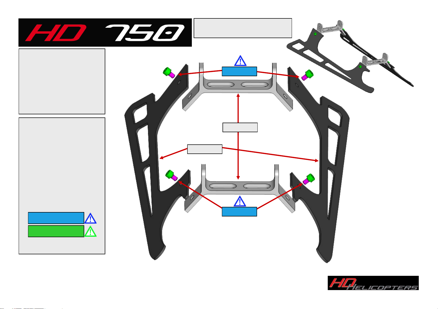
Step 1 Landing Skid
Parts:
2 x HD750-2061 Skid
2 x HD750-2021 Skid Mount
4 x D912-M4x6 Cap Bolt
HD750-2021
HD750-2061
D912-M4x6
Copyright 2016 All rights reserved by HD-Helicopters. www.hd-helicopters.com
Page 5
Assemble Skids as shown us-
ing Loctite 243 on all bolts.
Tighten M4 cap bolts with the
assembly on a flat surface.
D912-M4x6
Use Loctite 243
Use Loctite 648

Copyright 2016 All rights reserved by HD-Helicopters. www.hd-helicopters.com
Page 6
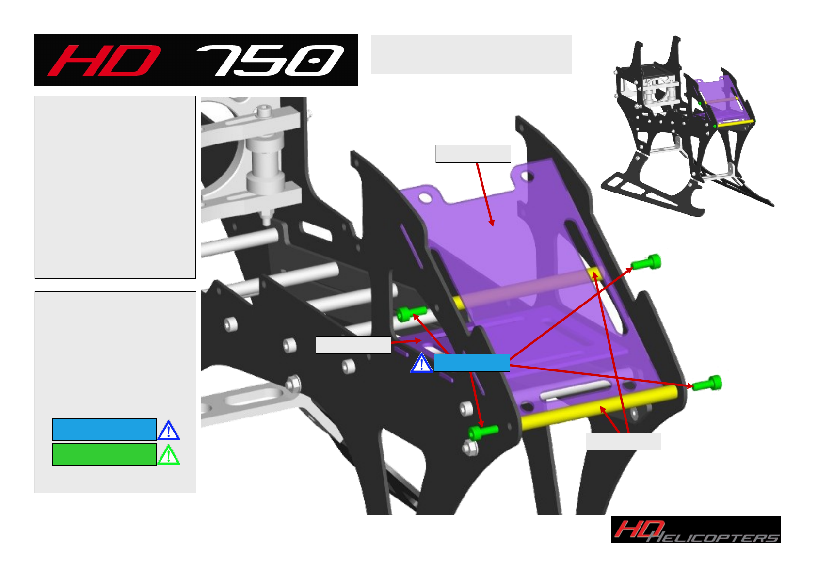
First install the battery
rails to the inside of both
main frames.
Mount Main Frames to
Skids using Loctite on all
hardware.
Using Loctite install the
frame separators as
shown in the illustration.
Parts:
2 x HD750-2001 Main Frames
2 x HD750-2018 Battery Rails
7 x HD750-2043 Frame Spacers
4 x D7991-M3x8 Taper Head Bolt
4 x D934-M3 Nut
4 x D912-M4x6 Cap Bolt
14 x D912-M3x8 Cap Bolt
HD 750 Cell DBDS
Step 2 Main Frame & Battery Sliders
D7991-M3x8
Install from the
inside out
HD750-2043
HD750-2001
D912-M3x8
Assemble both
sides the same
D912-M4x6
Assemble Both
sides the same
D934-M3
Nuts to outside of
frame sides
HD750-2018
Use Loctite 243
Use Loctite 648
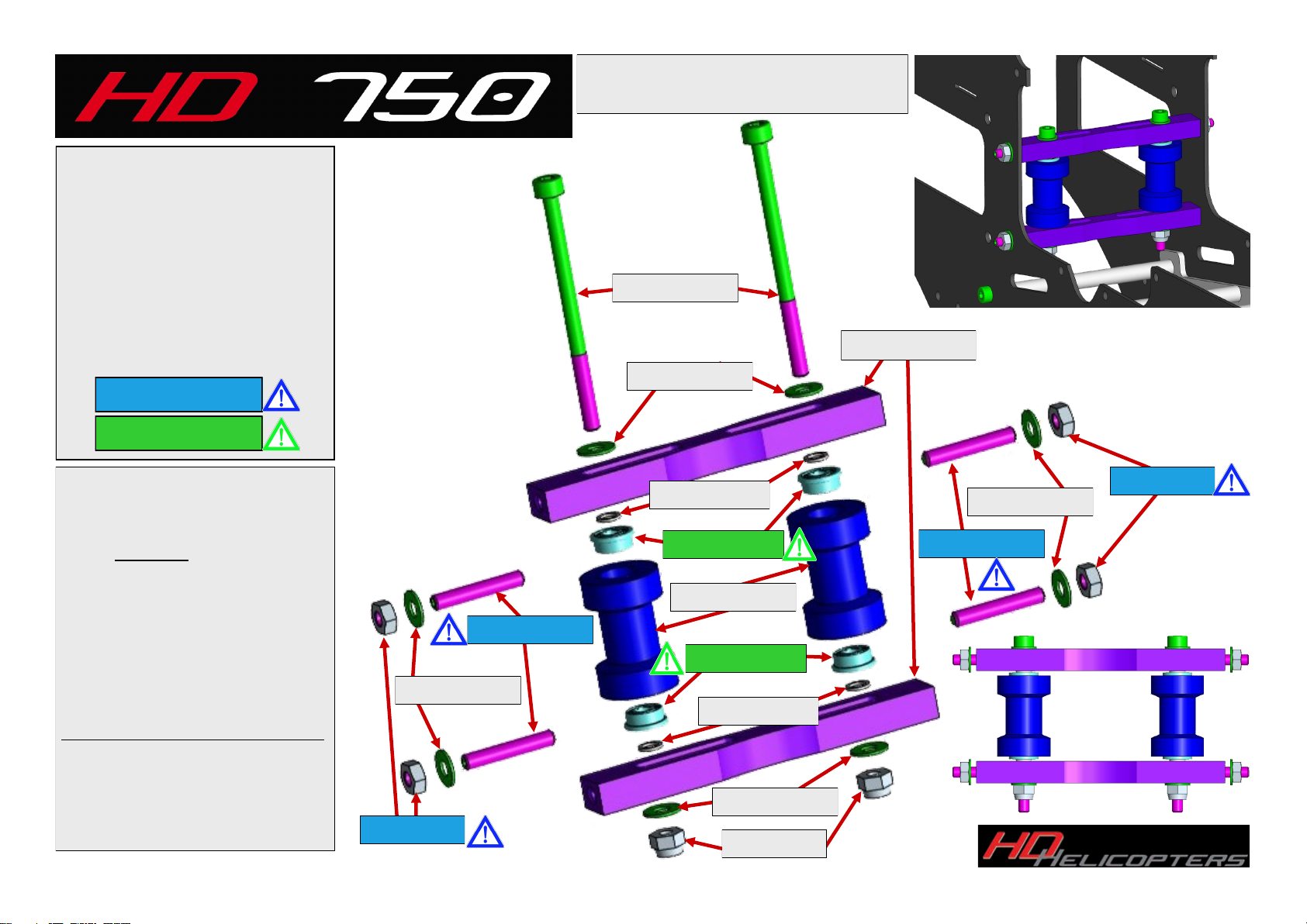
Parts:
2 x HD750-2023 Adjuster Mount
4 x HD750-2033 Bearing Spacer
2 x HD750-2041 Guide Pulley
4 x F683-2Z Bearings
4 x D912-M3x18 Grub Screws
2 x D912-M3x45 Cap Bolt
2 x D985-M3 Lock Nuts
4 x D934-M3 Nuts
8 x D125-3.2 Washers
Copyright 2016 All rights reserved by HD-Helicopters. www.hd-helicopters.com
Page 7
D985-M3
D912-M3x45
HD750-2023
D912-M3x18
Assemble the Tail Belt Adjuster
assembly before installing it into
the frames as shown in the dia-
gram. DO NOT Over-tighten the
M3x45mm Bolts this can cause
the pulley bearings to fail. Once
the pulleys are affixed to the
mounts install the unit into the
frame using the M3x18 Grub
Screws you may apply a small
amount of Loctite to these but
do not tighten them at this time,
finger tight is fine until the tail
belt is installed and ready for
vertical and belt tension adjust-
ment.
HD 750 Cell DBDS
Step 3 Tail Belt Guide Assembly
HD750-2041
F683-2Z
F683-2Z
D912-M3x18
HD750-2033
HD750-2033
D125-3.2
D125-3.2
D125-3.2
D125-3.2
D934-M3
D934-M3
Use Loctite 243
Use Loctite 648

HD 750 Cell DBDS
Step 4 Boom Clamps
Parts:
2 x HD750-2022 Boom Clamps
2 x HD750-2027 Pinch Bolts
1 x HD750-2014 FBL Mount
4 x D912-M4x12 Cap Bolt
4 x D125-4.3 Washer
4 x D934-M4 Nuts
Copyright 2016 All rights reserved by HD-Helicopters. www.hd-helicopters.com
Page 8
Install the FBL Plate (HD750-
2014) by snapping into place fol-
lowed by installing the Boom
Clamps as shown. Install all hard-
ware with Loctite. Do not tighten
the pinch bolts until later when
the boom is installed later on in
Step 13.
Important
Do Not over-tighten the pinch
bolts holding the boom. It can
damage the boom or the bolt.
HD750-2022
D934-M4
D125-4.3
D912-M4x12
HD750-2014
D934-M4
D125-4.3
HD750-2027
Use Loctite 243
Use Loctite 648
Copyright 2016 All rights reserved by HD-Helicopters. www.hd-helicopters.com
Page 9
HD 750 Cell DBDS
Step 5 ESC Mounting Plate
HD750-2015
Parts:
1 x HD750-2012 ESC Mount
1 x HD750-2013 CF Mount
2 x HD750-2015 Spacers
4 x D912-M3x8 Cap Bolt
HD750-2013
D912-M3x8
Install both CF plates before
installing the spacers as
shown. Do not tighten the
spacers until the CF Mounts
are in place, then tighten the
spacers using loctite on the
spacer bolts.
Use Loctite 243
Use Loctite 648
HD750-2012

HD 750 Cell DBDS
Step 6 Tail Box Assembly
Parts:
1 x HD750-3001 Tail Box
1 x HD750-3023 BC Mount
2 x D912-M2.5x8 Cap Bolt
Copyright 2016 All rights reserved by HD-Helicopters. www.hd-helicopters.com
Page 10
Install Tail Control Bell crank
Mount (BC Mount) as shown.
(*PLEASE NOTE THE
ORIENTATION OF THE
BELLCRANK MOUNT*)
HD750-3001
D912-M2.5x8
HD750-3023
*Please Note
Orientation*
Use Loctite 243
Use Loctite 648

Copyright 2016 All rights reserved by HD-Helicopters. www.hd-helicopters.com
Page 11
HD 750 Cell DBDS
Step 7 Tail Assembly
Parts:
1 x HD750-3002 Tail Spindle
1 x HD750-3005 Tail Pulley
1 x HD750-3006 Tail Spacer
2 x MF-126 2Z Bearing
1 x D6325-2x12 Lock Pin
1 x D913-M2x5 Grub Screw
Install Tail Spindle bearings as
shown. Using a small amount
of Loctite between the bearing
to the housing.
Please note direction of lip on
spacer HD750-3006 toward
the side bearing.
Slide Spindle from right side
installing the spacer with the
lip to outside followed by in-
stalling the pulley and lock pin.
Install Grub Screw with Lock-
tite to keep the pin for the tail
pulley in place..
HD750-3006
MF-126-2Z
D913-M2x5
D6325-2x12
Note Lip toward bearing
Install Pin
Loctite 243
HD750-3002
HD750-3005
Use Loctite 243
Use Loctite 648

Copyright 2016 All rights reserved by HD-Helicopters. www.hd-helicopters.com
Page 12
HD 750 Cell DBDS
Step 8 Tail Pitch Slider
Parts:
2 x HD750-3035 Pitch Arms
1 x HD750-3051 Slider Housing
1 x HD750-3052 Slider Bushing
1 x HD750-3053 Pitch Slider
1 x HD750-3055 Spacer
1 x HD750-1019 Spacer
1 x 9930XX Ball
2 x MR-128-2Z Bearings
4 x 682-X-2Z Bearings
1 x D912-M2x8 Cap Bolt
2 x D912-M2.5x14 Cap Bolt
2 x D985-M2.5 Lock Nuts
Install Tail Slider Bushing thru Bear-
ings and spacer using Locktite on
the threads.
Install Pitch arms onto the Pitch
slider as shown using Lock nuts as
shown. Assemble both sides the
same way
Install the Ball Link Ball using the
listed spacer as Shown Use Locktite
on bolt
HD750-3051
D985-2.5
HD750-3055
MR-128-2Z
HD750-1019
D912-2x8
DO NOT Over tighten the slider
bushing can cause damage.
HD750-3035
HD750-3052
MR-128-2Z
HD750-3053
F-682-X-2Z
D912-2.5x14
9930XX
Use Loctite 243
Use Loctite 648
Copyright 2016 All rights reserved by HD-Helicopters. www.hd-helicopters.com
Page 13
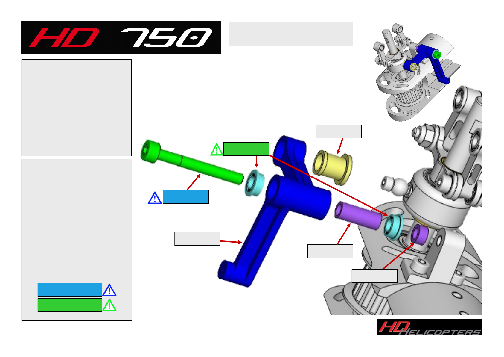
HD 750 Cell DBDS
Step 9 Bell crank & Pitch Slider
Parts:
1 x HD750-3025 Spacer
1 x HD750-3026 Bellcrank
1 x HD750-3027 Spacer
1 x HD750-3028 Bushing
2 x MF 683-2Z Bearings
1 x D912-M3x25 Cap Bolt
Press the plastic bushing into the
bell crank as shown you may
need to resize the bushing after
installation.
Slide the pitch slider assembly
onto the tail shaft then as shown
in the picture install the bell
crank making sure to use Lock-
tite on the bolt.
Do not over tighten the bolt this
can cause the crank to not move
freely.
D912-M3x25
HD750-3028
HD750-3027
MF 683-2Z
HD750-3025
HD750-3026
Use Loctite 243
Use Loctite 648

Copyright 2016 All rights reserved by HD-Helicopters. www.hd-helicopters.com
Page 14
HD 750 Cell DBDS
Step 10 Tail Grip Assembly
Parts:
6 x HD750-1019 Spacer
1 x HD750-3004 Tail Hub
2 x HD750-3033 Blade Grip
2 x HD750-3034 Spacer
4 x MR 105 2Z Bearing
4 x F_682_X_2Z Bearing
2 x F_5_10_M Bearing
2 x D912-M3x10 Cap Bolt
2 x D912-M2.5x10 Cap Bolt
2 x D913-M4x4 Grub Screw
2 x D125-3.2 Washer
Install Tail blade grips as shown
Make sure that the thrust bearing
half with the large inside diame-
ter goes on first also use a high
quality grease on this bearing
using care to not get any grease
on the threads of the Hub or
bolts. Use Locktite on the Bolts
Before installing the outer por-
tion of the pitch link install the
tail hub on the spindle using loc-
tite on the grub screws.
Now install the pitch links to the
grips making sure the assembly
is smooth after assembly.
HD750-3004
HD750-3033
D912-M2.5x10
D913-M4x4
D913-M4x4
HD750-1019
D125-3.2
F_5_10_M
HD750-3034
D912-M3x10
MR_105_2Z
Small ID to Outside
Large ID to Inside
F_682_X_2Z
Use Loctite 243
Use Loctite 648

Copyright 2016 All rights reserved by HD-Helicopters. www.hd-helicopters.com
Page 15
HD 750 Cell DBDS
Step 11 Tail Belt & Guide Roller
Parts:
2 x HD750-1019 Spacer
1 x HD750-1054 Tail Belt
1 x HD750-3007 Guide Pulley
1 x HD750-3008 Spacer
2 x F_682_X_2Z Bearing
1 x D912-M2.5x30 Cap Bolt
1 x D985-M2.5 Lock Nut
Install Tail Belt onto tail box be-
fore installing the belt guide.
You may apply a small amount of
grease to the outer spacers this
will help hold them in place dur-
ing installation.
When adjusting the roller make
sure it does not contact the tail
pulley should have approx 1mm
clearance from the pulley.
Do not over tighten bolt. Verify
the roller spins free after adjust-
ment has been made.
F_682_X_2Z
HD750-3008
HD750-3007
D985-M2.5
HD750-1054
HD750-1019
D912-M2.5x30
Use Loctite 243
Use Loctite 648

Copyright 2016 All rights reserved by HD-Helicopters. www.hd-helicopters.com
Page 16
HD 750 Cell DBDS
Step 12 Tail Boom
Parts:
1 x HD750-2068 Tail Fin
1 x HD750-3009 Rod Guide
1 x HD750-3056 Tail Boom
2 x D912-M3x6 Cap Bolt
2 x D912-M3x8 Cap Bolt
1 x D912-M2.5x8 Cap Bolt
Install the tail control guide on
boom set to approx 480mm from
rear of boom (do not tighten
2.5mm bolt at this time).
Noting the rotation of the tail belt
install the belt thru the boom as
shown. Line up tail box with
mounting holes and using Loctite
mount the tail fin and tighten the
four M3x6 bolts. Taking care to
not over-tighten.
480mm
Approx
HD750-3009
HD750-3056
HD750-2068
D912-M2.5x8
D912-M3x6
D912-M3x8
Use Loctite 243
Use Loctite 648

Copyright 2016 All rights reserved by HD-Helicopters. www.hd-helicopters.com
Page 17
HD 750 Cell DBDS
Step 13 Mating the Boom
By following this step you will find the
mechanical assembly will drop into place
with ease after it’s assembly.
Insert Tail Boom into boom clamps
please take note to set the boom at
90° right angle to frame.
Important!
Install boom 3mm thru the front
boom clamp. This is a fixed distance
and must be set to this length before
tightening the boom-clamps.
3mm
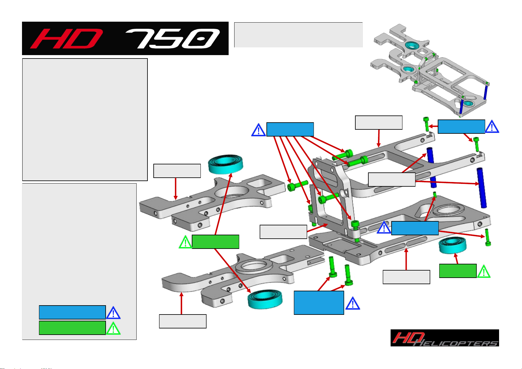
Install the Main and secondary
shaft bearings by heating the cell
using a hair drier or heat gun,
this will allow the bearings to
slide in.
Assemble the front section of the
cell making sure to use Loctite on
all of the bolts followed by the
rear sections of the cell please
note the direction of the parts as
shown otherwise bearings can
move causing damage to the
Helicopter.
Copyright 2016 All rights reserved by HD-Helicopters. www.hd-helicopters.com
Page 18
HD 750 Cell DBDS
Step 14 The Cell
HD750-2007
HD750-2011
HD750-2005 698_2Z
Parts:
1 x HD750-2004 Upper Cell FRT
1 x HD750-2005 Lower Cell FRT
1 x HD750-2007 Upper Cell Rear
1 x HD750-2011 Lower Cell Rear
1 x HD750-2024 Center Cell Tower
2 x HD750-2025 Spacer
2 x 61901_2Z Bearing
1 x 698_2Z Bearing
6 x D912-M3x12 Cap Bolt
2 x D6912-M3x12 Shoulder Cap Bolt
2 x D912-M2x8 Cap Bolt
2 x D912-M2x10 Cap Bolt
D912-M3x12
D6912-M3x12
Shoulder Bolt
61901_2Z
D912-M2x10
HD750-2024
HD750-2025
D912-M2x8
HD750-2004
Use Loctite 243
Use Loctite 648
Copyright 2016 All rights reserved by HD-Helicopters. www.hd-helicopters.com
Page 19
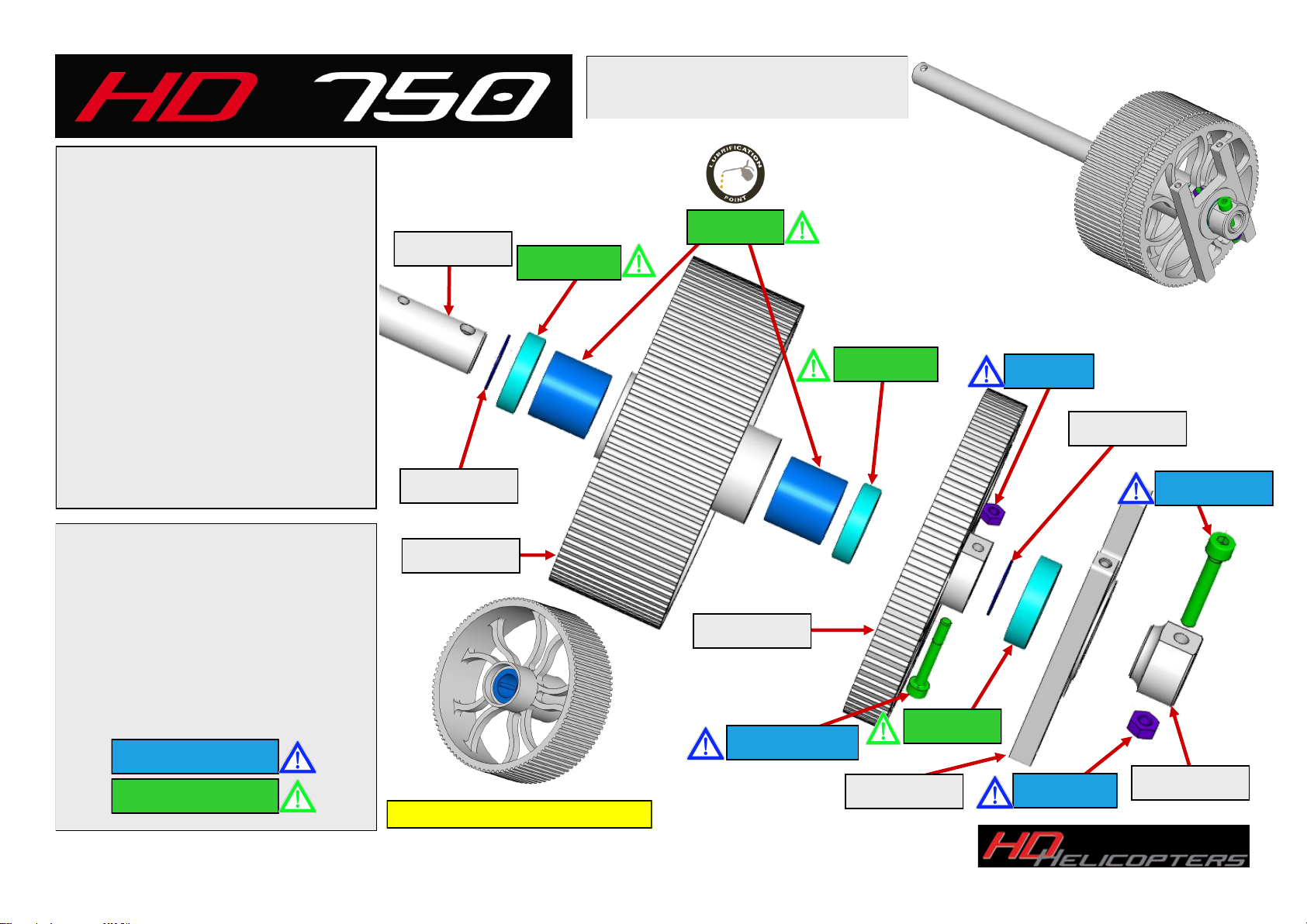
HD 750 Cell DBDS
Step 15 Pulley Stack
Assemble the pulley stack onto the
mainshaft in the order shown. Use a
light oil on the One Way Bearings Tri-
Flow is a good option.
Be sure to use Loctite on the M3 and
M4 bolts to ensure they do not come
loose.
Parts:
1 x HD750-2000 Tail Pulley
1 x HD750-2010 Lower Bearing Block
2 x HD750-2035 Spacer
1 x HD750-2038 Main Pulley
1 x HD750-2044 Mainshaft
1 x HD750-2045 Retainer
2 x 61801_2Z Bearing
1 x 61901_2Z Bearing
2 x HF1216 One-Way Bearing
1 x D912-M4x25 Cap Bolt
1 x D934-M4 Nut
1 x D912-M3x25 Shoulder Bolt
1 x D934-M3 Nut
HD750-2000
One Way Bearings Pre-Installed
HF1216
D934-M3
61901_2Z
D934-M4
HD750-2035
HD750-2044
HD750-2038
D912-M3x25
HD750-2045
D912-M4x25
61801_2Z
61801_2Z
HD750-2035
HD750-2010
Use Loctite 243
Use Loctite 648
Popular Toy manuals by other brands


Baby Einstein
Baby Einstein Zen's Activity Milestones 16636-WW manual

Little Partners
Little Partners the learning Tower LP0141 R3 manual

Horizon Hobby
Horizon Hobby A-10 instruction manual

Fisher-Price
Fisher-Price GCW11 Assembly guide

Toys for life
Toys for life SYMETRIX instructions

Mattel
Mattel Mega Bloks Hot Wheels Super Stunt Test... manual