Installation, Operation & Maintenance Manual
1. Scope
2
Sussman l ctric hot wat r boil rs provid saf , v rsatil , asy to us h at sourc s for low or high pr ssur hot wat r in
industrial, comm rcial, or spac h ating applications.
2.1 Principles of Operation
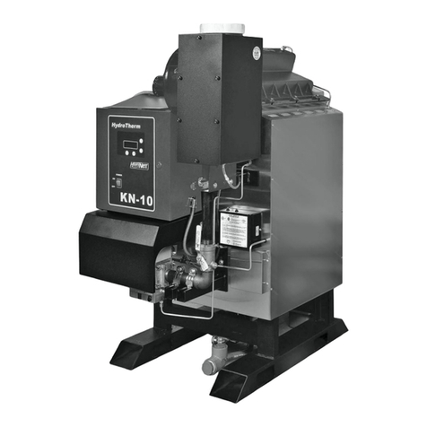
2.1.1 Sussman SVW l ctric hot wat r boil rs utiliz
stat of th art t chnology, control compon nts,
valv s and acc ssori s. Th S ri s SVW f atur s v rti-
cally position d h ating l m nts which hav many
advantag s ov r horizontally position d l m nts:
a.Sinc th l m nts ar r mov d from th top, th
boil r r quir s l ss spac .
b.V rtical hot wat r boil r l m nts ar l ss pron to
scal build-up, a major caus of l m nt failur .
c. Boil rs with v rtical l m nts, b ing mor compact,
hav fast r r spons tim than boil rs r quiring larg-
r v ss ls.
2.1.2 El ctric boil r op ration:
a. A st l v ss l is fitt d with tubular r sistanc typ
h ating l m nts, inl t and outl t conn ctions, a
drain/blowdown valv (s), an air v nt, a wat r control
m chanism, a pr ssur r li f valv , and a t mp ra-
tur control. Th s d vic s ar configur d with a
s ri s of l ctrical controls for automatic op ration.
b. Wh n th boil r is switch d on, an l ctronic l v l
s nsor first d t cts if a low wat r l v l condition
xists.
If th s nsor d t cts a low wat r l v l condition, th
h at rs will not n rgiz until wat r is introduc d
through th piping syst m at th boil r inl t.
If a low wat r l v l condition do s not xist, th s n-
sor will activat th l m nts and imm diat ly b gin
to h at th wat r.
c. Th air v nt at th top of th boil r allows air to xit
th boil r as it fills.
If air and oth r gas s ar not liminat d from th
flow circuit, th y may caus failur of th h ating
l m nts and nois in th piping circuit.
This manual d tails th installation, op ration and maint -
nanc instructions, and spar parts list for Sussman S ri s SVW
Hot Wat r Boil rs.
R f r to s ction 6.0 for sp cific drawings and bills of mat rial
for r lat d quipm nt suppli d und r this ord r.
Sussman hot wat r boil rs ar d sign d and manufactur d
to m t A.S.M.E. and cod r gulations. Wh n prop rly
op rat d and maintain d, you can xp ct y ars of troubl
fr s rvic .
Car fully follow th instructions outlin d in this manual to
nsur prop r installation and p rformanc of your boil r.
d. In forc d r circulating syst ms, th n c ssary flow through
th boil r is maintain d by a circulation pump (by oth rs).
For most calculation purpos s, pr ssur drop through th
boil r can b assum d to b th quival nt of 10 ft. of
standard inl t piping siz
Flow through th boil r nt rs at th inl t (bottom of th
boil r) and xits through th outl t (top of th boil r).
. Th boil r is controll d by s nsing wat r t mp ratur .
An adjustabl t mp ratur controll r will switch off th
h at rs wh n th s t t mp ratur is r ach d. Th t mp ra-
tur controll r is back d up by a high limit t mp ratur
controll r.
In th v nt that th boil r t mp ratur ov rshoots th
high limit s t point, th controll r will trip and d - n rgiz
all th h ating circuits.
Th high limit t mp ratur controll r must th n b manu-
ally r s t b for th h at rs will com back on.
N te: Cycling n the high limit is unacceptable. The cause
f a high limit trip must be determined and rectified bef re
resetting the limit.
f. All boil rs ar fitt d with a pr ssur r li f valv which will
op n if th pr ssur approach s a s t point chos n to b
w ll b low th withstand pr ssur of th boil r and syst m
compon nts.
g. Drain and/or blowdown valv (s) locat d at th bottom of
th boil r ar provid d for maint nanc purpos s. Boil rs
should pr f rably b install d with flang d conn ctions or
unions with stop valv s on th inl t and outl t to allow th
boil r to b drain d without draining th ntir syst m and
to simplify s rvicing.
h. P riodic insp ctions of th v ss l int rior will giv
advanc d notic of an imp nding probl m. Th local boil r
insp ction authority is availabl for guidanc in th s
instanc s.
2. Operating Principles


