manuals.online logo
Brands
  1. Home
  2. •
  3. Brands
  4. •
  5. Bosch
  6. •
  7. Boiler
  8. •
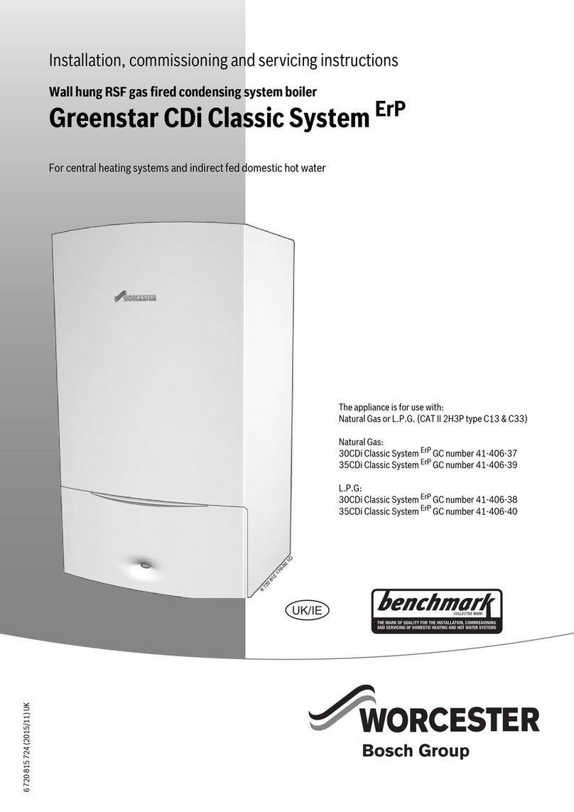
  9. Bosch Worcester Greenstar 350 Combi Operation instructions

Bosch Worcester Greenstar 350 Combi Operation instructions

W
RCESTER
Bosch Thermotechnik
35
c
bi
WALL
MOUNTED
COMBINATION
BOILER
FOR
CENTRAL
HEATING
AND
MAINS
FED
DOMESTIC
HOT
WATER
USERS
G
INST
IMP
OR
T
AN
T:
THIS
APPLIANCE
IS
F
OR
USE
WITH
NA
TU
RA
LG
AS
ONLY
THESE
INSTRUCTIONS
APPLY
IN
THE
UK
ONLY
THESE
INSTRUCTIONS
ARE
TO
BE
LEFT
WITH
THE
US
ER
OR
AT
THE
GAS
METER
·
··-
.J
£
;>JJO
!
;';f;~>y~"":-
""'~
;;""-~l~~~"~"'
,_"
"'
,
':
~
',
\,,
~
;',SMs~~~,,~,~,l!~l:~n
,, ,
~ ~
, ,
~,
~
~ "'~
"
"'
~
:
",
-~
2 "
,s":
2"',1 ,
:w~'"'~
;
~
'"'
"
SEALED
WATER
SYSTEM
The
Worcester
350
is
designed
to
operate
on
a sealed system
only.
To
ensure that the appliance operates
correctly
a
minimum
water operating pressure must
be
maintained.
The
minimum
pressure
required
for
your appliance
is
indicated
by
the
green
needle
on
the pressure
gauge,
which
is
located
on
the
facia
panel.
If the pressure
falls
below this
level
to the minimum the red
indicator
light
on
the
facia
panel
will
light.
In
the event that the
red
light
operates, the system must
be
re·
pressurised
using
the method described
by
your
installer.
:l
"v,,,tR"'':
,~;-c£,-:
1
,Yi"'(~,~~/"',.7J1;~,;<~~er:~~tf"f''/t,~t>;z;:;
/0'~::~~1f"'
4'"
~t,
2
: ,
'·
:·.
··.
$!~fill~.
~:~~si~·e:~~tii~i;JJ;
:
~,
· .\··
"''!
""
"'<
0
i''
~
>!~X
/':<
~
«
,'
~kz"'J
'j
;;:;
{ "'
r'c~
/~a"'<:,;,<'
f
~,....,4'<
Vi"'
~~"'C
" J
"'
'
CLEARANCES
Your
Installer
will
have
provided
space around the appliance
for
safety
and
servicing.
It
is
important that
you
do
not restrict this
space.
The
minimum
clearances
are:
Left-hand
side
Right-hand
side
Top
Below
In
front
5mm.
5mm.
35mm.
200mm.
600mm.
If
the
flue
is
connected to the side
of
the appliance then a
clearance
of
25
mm
is
required
at that
side.
Fig. 1.
To
ensure
that
the boiler and system are
full
of
water and
pressurised, check the white pressure needle
on
the pressure
gauge. Contact your installer
or
maintenance engineer
if
the
system continues
to
lose
pressure
as
this
may
indicate
a
leak.
CENTRAL
HEATING
SYSTEM
During
the
first
operation
of
the heating system,
check
that
all
radiators
are
heated
evenly.
If
the
top
of
the radiator
is
at a
lower
temperature than the bottom, then vent
it
by
releasing air
through the vent
screw
at the top
of
each
radiator.
Please
refer
to
the
preceding
paragraph
as
excessive
venting
may
cause a
drop
in
system pressure.
FLUE
OPERATION
In
cold
weather,
vapour
may
be
emitted
from
the
flue.
This
is
a
normal operating characteristic and
no
remedial action
is
necessary.
VENTILATION
This
is
a room sealed appliance and ventilation openings
provided
by
the installer
in
a
wall
or
door
must not
be
blocked.
The
flue
terminal
in
the outside
wall
must not
be
obstructed
or
damaged.
Do
not place any combustible matP.rial
nn
nr arnund the
appliance.
CUPBOARD
INSTALLATION
If
the appliance
is
fitted
in
a cupboard
and
the cupboard
is
to
be
used
for
storage, as
in
an
airing
cupboard
for
clothes, the
airing
space must
be
separated
from
the boiler and
flue
so
that
no
combustible material
may
come
into
contact
with
the appliance
or
the
flue,
or
restrict
any
permanent
air
vent
which
may
have
been
installed.
Please
consult your
Gas
Region
or
Worcester
Heat
Systems
Ltd.
for
advice should you wish
to
fit
a compartment around the
appliance after installation.
tL-f---
Overheat
Thermostat
Reset
Button
Sightglass
(behind
front
panel)
J J
Indicator
Lights
,
....
\ ,
......
\
'-~' '-~'
Amber-
Standby
Green
-
Demand
1-----------:-ld
Red-
Low
System
Pressure
I
,.,,
, I
"r~·~~~
8
""""j"
1
Central
Heating
Temperature
Control
l
"'""":::
9_j
t·.0.'
01--
Central
Heating
System
Pressure
Gauge
~~!.,_-~==.t=~==~:}--
Operating
Switch
(or
programmer)
L__
Gas
Service
Cock
The Worcester
350
is
a combination boiler which will supply
mains fed domestic hot water plus central heating
at
an
output
of
between 9.0 and 25
kW.
HOT
WATER
PROVISION
When a
tap
is
turned
on
the appliance
will
begin
to
operate. Hot
water
will
become available
at
the tap
in
a continuous supply
at
a
constant
temperature, after a short delay, depending
on
when
the
appliance was last fired. The fan
will
continue to run
for
a few
seconds after the tap has been turned
off,
to remove any residual
heat from the appliance.
CENTRAL
HEATING
AND
HOT
WATER
PROVISION
A
demand
for
hot water
will
take priority over the supply of
heat
to
the
central heating system. The
burner
will
remain
off for
approximately three minutes after the demand
for
hot
water
is
completed
before
automatically
returning to
central
heating
operation.
CENTRAL
HEATING
PROVISION
When a demand
is
made
for
central heating the burner
will
light
at
its minimum
output
before rising to
the
preset
maximum
output. The appliance
will
then automatically
match
output
to
the
system load.
In
the event of
the
system requiring less
than
9
l<W,
the
burner will light only periodically
to
maintain
system
temperature.
When
the
automatic
controls close
the
burner
down, the fan
will
continue to operate
for
a
few
seconds.
The
appliance
Serial
Number
must
be
quoted
in
any
correspondence.
It
will
comprise
C350RSF
and a 10-digit number.
It can be seen through the lower opening
in
the inner cover panel
accessible
by
removing the cabinet front panel.
CENTRAL HEATING
AND
HOT
WATER
PROGRAMME
CONTROL
Your
Worcester
350
is
fitted with either a 3-position Operating
Switch or
an
Electronic Programmer
on
the
facia panel for
the
control of domestic hot water and central heating.
OPERATING
SWITCH
The switch offers the following positions:
WATER
The
appliance
will
provide
hot
water
when a tap or shower
is
turned on.
OFF
Both
the
central heating
and
domestic
hot
water
will
remain
off.
HEATING
&
WATER
The
central~heating
will
operate
in
response
to
any
system
controls
and
domestic hot water
will
be supplied when
a tap or shower
is
turned on.
ELECTRONIC
PROGRAMMER
Your
Installer
may
have
mounted
the
optional
electronic
programmer
on
the appliance facia panel.
For
full
details
on
how
to
operate
the
Programmer
please
refer
to
the
Operating
Instructions which are supplied with the Programmer.
CENTRAL
HEATING
TEMPERATURE
CONTROL
The
temperature control knob
on
the facia panel allows control
ofthe water temperature to the radiators.
INDICATOR
LIGHTS
There are three indicator lights
on
the
facia panel.
The
red light when
on
indicates
that
the system pressure
is
too
low (see System Operation). The amber light when
on
indicates
that
the
mains electricity to
the
appliance
is
on.
The
green light
when
on
indicates
that
the
appliance
is
supplying
either
domestic hot water or central heating.
PRESSURE
GAUGE
A
pressure
gauge
is
located
on
the
facia
panel.
The
green
pressure needle
has
been
preset
to
show
the
water
pressure
which is required for
the
appliance to operate effectively. The
white pressure needle
will
show
the
amount
of water pressure
in
your particular system.
If
the
pressure drops below the required
minimum
pressure
the
red
indicator
will light. For remedial
action please refer to System Operation.
By
slightly reducing the flow of domestic hot water from the tap,
the temperature of the
water
will increase. This
is
of particular
advantage
in
the
winter, for
example
to increase
bath
water
temperature and to remove heavy grease deposits
on
plates, etc.
Also
this
will
provide an
added
advantage of reducing
the
delay
before
hot
water
is
obtained.
The
maximum discharge temperature of hot water to the taps
is
preset
at
the factory.
TO
LIGHT
THE
APPLIANCE
Make sure
that
the appliance is off by:
(a)
Positioning the Operating Switch or Programmer to
OFF.
(b)
Switching
the
mains electricity
off.
Turn
the gas service cock
on
and
check
that
all
the water valves
to
the
central heating
supply
are open. Check
that
the
white
needle
on
the pressure gauge
is
not
below the required pressure.
See
Fig.
1.
Switch
on
the
mains
electricity
and
turn
the
central
heating
temperature control knob to max. Set the Operating Switch
(or
Programmer) to
HEATING
&
WATER.
This will light
the
main
burner.
The
burner
can
be
seen
through
the
sightglass
which
is
accessible by removing
the
cabinet front panel.
To
remove the
panel, pull it away
at
the
bottom
and
lift
it
off
the
top support.
Set
the
Operating
Switch
(or
Programmer)
to
the
required
position.
If
a room thermostat
is
fitted to
the
system,
set
to
the
desired
temperature. Set the central heating temperature control knob to
the required position.
FAILURE
TO
LIGHT
If
the
appliance fails to light
or
it locks our during operation,
switch
the
operating
switch
to
OFF
and
then
to
ON.
If
the
appliance fails to light after several
attempts
at
ignition check
the overheat thermostat by pressing the reset button.
In
the event
that
the problem continues call a Service Engineer.
TO
STOP
THE
APPLIANCE
For Short Periods
Set the Operating Switch (or programmer) to
OFF.
For Long Periods
Set the Operating Switch (or programmer) to
OFF.
Switch off the mains electricity. The facia mounted programmer
will retain its settings for
about
four weeks after which it
will
return to the factory
set
programme. The display
will
disappear
after approximately 12 hours.
Appliance and System
Care
.
SERVICE
Annual
servicing
of
your
350
is
important
to
ensure
efficiency
and
prolong
the
life
of
your
appliance
.
Worcester
Heat
Systems
or your
Gas
Region can offer service
contracts
for the
maintenance
of
your
appliance.
CLEANING
To
clean
your
appliance
use
a
damp
cloth
and a
little
detergent.
Do
not
use
abrasive
cleaners
on
the
casing
.
FROST
PRECAUTIONS
Afrost thermostat, suitable
for
mains
voltage,
may
have
been
fitted
by
your
installer.
If
the 350 has not been
fitted
with
a
frost
thermostat
and
is
not
to
be
used
for
a
long
time
in
a
period
of
cold weather then the appliance and the system should
be
drained.
For
short periods leave the appliance on a low
temperature
setting.
USE
IN
HARD
WATER
AREAS
The
350 has
been
designed
to
overcome
scale
accumulation
in
most normal conditions.
However,
in
exceptionally
hard
water
areas a
Worcester
scale
inhibitor
can
be
fitted
to
prevent
scale
formation.
system
Fitting
ROOM
THERMOSTAT
A
room
thermostat, suitable
for
mains
voltage,
can
be
fitted
for
improved
control
of
the
room
temperature.
THERMOSTATIC
RADIATOR
VALVES
Thermostatic radiator valves fitted to your central heating
system must
conform
to
852767.
10
.
SHOWERS,
BIDETS,
TAPS
AND
MIXING
VALVES
laps and
mixing
valves
used
with
the 350 must
be
suitable
for
operating at a
mains
pressure.
Thermostatically controlled shower valves
will
give
added
comfort
and
safeguard
against
excessive
temperatures.
Hot
and
cold
mains
fed
water can
be
supplied
direct
to
an
over-
rim
flushing
bidet
subject
to
local
Water
Company
requirements.
If
a
loose-head
shower
with
a
flexible
hose
is
to
be
used
over
a
bath, the
hose
must
be
fixed
so
that the head cannot
fall
closer
than
25
mm
(1
in.)
above
the
top
edge
of
the bath
to
prevent
its
immersion
in
bath water. Alternatively the shower must
incorporate or
be
fitted
with
an
anti-syphonage
device
at the
point
of
the
flexible
hose
connections.
HOT
AND
COLD
FLOW
The
flow
of
water
from
the hot and
cold
taps depends
on
the
mains water
pressure
and
it
may
not
be
possible,
in
some
homes
to
operate a
number
of
taps simultaneously.
To
ensure
an
even
supply
of
water
to
all
outlets
individual
flow
regulators
may
be
fitted
to
the supply
pipes
to
provide
an
even
water distribution.
Mains Service Interruptions
. ,.
GAS
LEAK
If
you
suspect a gas
leak,
turn
off
the appliance and
call
your
local
Gas
Region.
WATER
MAINS
FAILURE
In
the
event
of
mains
water
supply
failure
no
domestic hot water
will
be
available
from
the
appliance.
However,
the central heating
will
continue
to
operate.
ELECTRICITY
SUPPLY
FAILURE
If the supply
of
electricity
fails
the appliance
will
not operate.
Once
the supply
is
restored
the
appliance
will
return
to
normal
operation.
If
a programmer
is
fitted please check that the
settings
have
been
maintained.
To
Connect
a
-
P~~~
":
,
' ' "
~
The
colour
of
the
wires
in
the
mains
lead
of
the appliance
may
not correspond with the coloured markings identifying the
terminals
in
your
plug.
In
this
case
please
proceed
as
follows
:
The
wire
coloured
green
and
yellow
must
be
connected
to
the
terminal
in
the
plug
that
Is
marked
with
the letter
E,
or
by
the
earth
symbol
~,
or
coloured
green
or
green
and
yellow.
The
blue wire must be connected
to
the terminal which
is
marked
with
f2ither
the
let
t
er
Nor
mlmm'!rl
hlilr.k
The
brown
wire
must
be
connected
to
the terminal
which
is
marked
with
the letter L
or
coloured
red
.
GAS
SAFETY
(INSTALLATION
AND
USE)
REGULATIONS
1984:
It
is
the
law
that
all
gas
appliances
are
installed
by a
competent person in accordance with the above regulations.
Failure
to
install
appliances
correctly
could
lead
to
prosecution.
It
is
in
your interest and that
of
safety, to ensure
compliance with the
law.
The
manufacturers notes must not
be taken,
in
any
way,
as over-riding statutory obligations.
WARNING
This
appliance
must
be
earthed and protected
by
a 3 amp
fuse
if
a
13
amp
plug
is
used.
If
any
other type
of
plug
is
used a 5
amp
fuse
must
be
fitted
in
the
plug
or
adaptor
or
at the distribution
board.
~~~ORCESTER
Bosch Thermotec
hn
ik
Worcester Heat
Systems
Limited,
Cot
swold
Way,
Warndon, Worcester
WR4
9SW.
Telephone:
(01905)
754624
Fax:
(01905) 754619
This
booklet
is
accurate
at the date
of
printing but
will
be
superseded
and
should
be
disregarded
if
specifications
and/
or
appearances
are
changed
in
the i
nte
rests
of
continued
i
mprovement.
All
goods
sold
are
subiect
to
Qur
officia
\
Condit
_i
ons
of
Sale
, a
cop
y
of
which
may
be
obtained
on
applicat
i
on.
8
716
115
058a

Other Bosch Boiler manuals

Bosch ZBR16-3A User manual

Bosch

Bosch ZBR16-3A User manual

Bosch Worcester Danesmoor Utility Regular ErP+... User guide

Bosch

Bosch Worcester Danesmoor Utility Regular ErP+... User guide

Bosch Buderus SSB399 Use and maintenance manual

Bosch

Bosch Buderus SSB399 Use and maintenance manual

Bosch WORCESTER GREENSTAR HE ZB 7-27 User manual

Bosch

Bosch WORCESTER GREENSTAR HE ZB 7-27 User manual

Bosch Greenstar ZBR 16-3 A Series Operating instructions

Bosch

Bosch Greenstar ZBR 16-3 A Series Operating instructions

Bosch CONDENS 5000W User manual

Bosch

Bosch CONDENS 5000W User manual

Bosch benchmark Greenstar12i User manual

Bosch

Bosch benchmark Greenstar12i User manual

Bosch Condens 8300i W User manual

Bosch

Bosch Condens 8300i W User manual

Bosch Worcester GREENSTAR 12i System User manual

Bosch

Bosch Worcester GREENSTAR 12i System User manual

Bosch Singular 4000 User manual

Bosch

Bosch Singular 4000 User manual

Bosch GREENSTAR HEATSLAVE II EXTERNAL 12/18 User manual

Bosch

Bosch GREENSTAR HEATSLAVE II EXTERNAL 12/18 User manual

Bosch TR4000 18 EB User manual

Bosch

Bosch TR4000 18 EB User manual

Bosch Worcester 24CDi User manual

Bosch

Bosch Worcester 24CDi User manual

Bosch Uni Condens 8000 F UC8000F User manual

Bosch

Bosch Uni Condens 8000 F UC8000F User manual

Bosch WORCESTER GREENSTAR DANESMOOR WALL MOUNTED OIL... User manual

Bosch

Bosch WORCESTER GREENSTAR DANESMOOR WALL MOUNTED OIL... User manual

Bosch ZWB28-3A User manual

Bosch

Bosch ZWB28-3A User manual

Bosch 47 311 67 User manual

Bosch

Bosch 47 311 67 User manual

Bosch ZSB 30-2 A User guide

Bosch

Bosch ZSB 30-2 A User guide

Bosch Worcester Greenstar Danesmoor User manual

Bosch

Bosch Worcester Greenstar Danesmoor User manual

Bosch SSB120 Operating instructions

Bosch

Bosch SSB120 Operating instructions

Bosch Worcester Greenstar CDi Conventional Series User manual

Bosch

Bosch Worcester Greenstar CDi Conventional Series User manual

Bosch Uni 3000 F User manual

Bosch

Bosch Uni 3000 F User manual

Bosch Jungers ELAFLUX ED 18-1 HE User manual

Bosch

Bosch Jungers ELAFLUX ED 18-1 HE User manual

Bosch TWK7101 User manual

Bosch

Bosch TWK7101 User manual

Popular Boiler manuals by other brands

Viessmann VITODENS 333 Service instructions

Viessmann

Viessmann VITODENS 333 Service instructions

ACV Smart SL 100 Installation operation & maintenance

ACV

ACV Smart SL 100 Installation operation & maintenance

Grant Combi 70 V3 User's installation guide

Grant

Grant Combi 70 V3 User's installation guide

Wolf CSW-120 installation instructions

Wolf

Wolf CSW-120 installation instructions

Bio Bronpi HYDROBOX Installation, operating and servicing instructions

Bio Bronpi

Bio Bronpi HYDROBOX Installation, operating and servicing instructions

Vaillant ecoTEC VU 466/4 Installation and maintenance instructions

Vaillant

Vaillant ecoTEC VU 466/4 Installation and maintenance instructions

Ariston CLAS HE R 24 user manual

Ariston

Ariston CLAS HE R 24 user manual

Burnham LE L7248 Operation and service instructions

Burnham

Burnham LE L7248 Operation and service instructions

SCHUSTER SWG A 23 Installation and Servicing Manual

SCHUSTER

SCHUSTER SWG A 23 Installation and Servicing Manual

Econo Heat OWB-9 Installation & operation manual

Econo Heat

Econo Heat OWB-9 Installation & operation manual

Riello Condexa Pro3 Series installation instructions

Riello

Riello Condexa Pro3 Series installation instructions

Baxi Bermuda BBU 15 HE Installation & servicing instructions

Baxi

Baxi Bermuda BBU 15 HE Installation & servicing instructions

Clyde CKRS 05 datasheet

Clyde

Clyde CKRS 05 datasheet

Windhager PUROWIN PWPE 60 installation instructions

Windhager

Windhager PUROWIN PWPE 60 installation instructions

Buderus G234X/64 Installation and service instructions

Buderus

Buderus G234X/64 Installation and service instructions

U.S. Boiler Company PVG PVG-3 Installation, operating and service instructions

U.S. Boiler Company

U.S. Boiler Company PVG PVG-3 Installation, operating and service instructions

SENKO SENel instruction manual

SENKO

SENKO SENel instruction manual

Immergas VICTRIX 26 2 I Instruction booklet and warning

Immergas

Immergas VICTRIX 26 2 I Instruction booklet and warning

manuals.online logo
manuals.online logoBrands
  • About & Mission
  • Contact us
  • Privacy Policy
  • Terms and Conditions

Copyright 2025 Manuals.Online. All Rights Reserved.