Heath Company Heathkit SB-220 User manual
LINEAR AMPLIFIER
MODEL
SB-220

Assembly
and
Operation
of
the
LINEAR AMPLIFIER
MODEL
SB-220
HEATH
COMPANY
BENTON
HARBOR, MICHIGAN
49022
Page
2
~~~-=m~
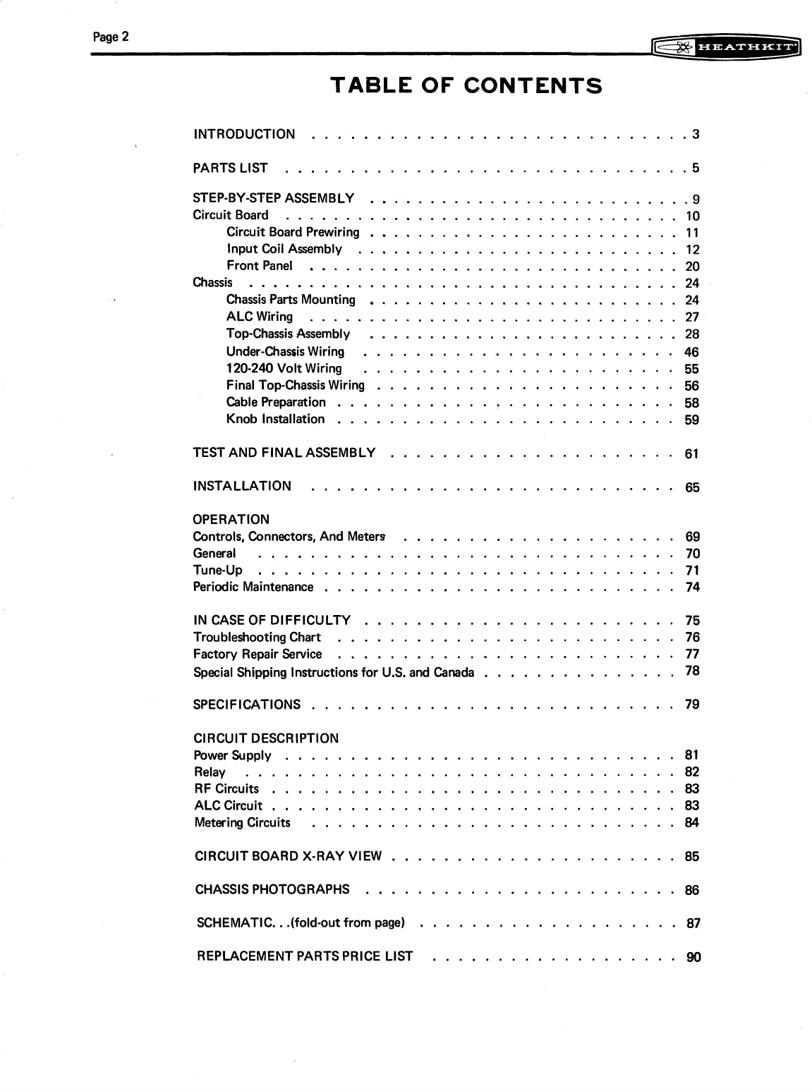
TABLE OF CONTENTS
INTRODUCTION
.............................
3
PARTS LIST
...............................
5
STEP-BY-STEPASSEMBLY
...........................
9
Circuit Board
.................................
10
Circuit Board Prewiring
..........................
11
InputCoil Assembly
...........................
12
Front Panel
...............................
20
Chassis
....................................
24
Chassis Parts Mounting
..........................
24
ALCWiring
...............................
27
Top-ChassisAssembly
..........................
28
Under-ChassisWiring
........................
46
........................
120-240
Volt Wiring
55
FinalTop-ChassisWiring
.......................
56
Cable Preparation
..........................
58
Knob Installation
..........................
59
TEST AND FINALASSEMBLY
......................
61
INSTALLATION
............................
65
OPERATION
Controls. Connectors. And Meters
.....................
69
General
................................
70
Tune-up
................................
71
...........................
Periodic Maintenance
74
INCASE OF DIFFICULTY
........................
75
TroubleshootingChart
..........................
76
Factory Repair Service
..........................
77
...............
Special Shipping Instructionsfor U.S. and Canada
78
............................
SPECIFICATIONS
79
CIRCUIT DESCRIPTION
PowerSupply
..............................
81
Relay
.................................
82
RF Circuits
...............................
83
ALC Circuit
...............................
83
MeteringCircuits
............................
84
CIRCUIT BOARD X-RAY VIEW
......................
85
CHASSIS PHOTOGRAPHS
........................
86
SCHEMATIC
..
.(fold.out from page)
....................
87
REPLACEMENTPARTSPRICE LIST
...................
90
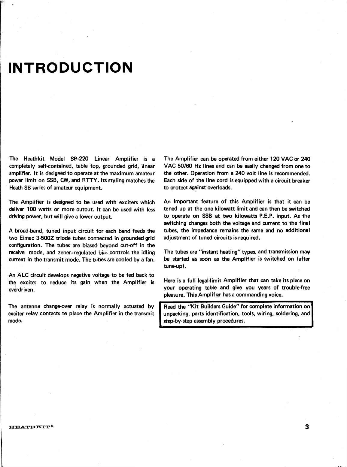
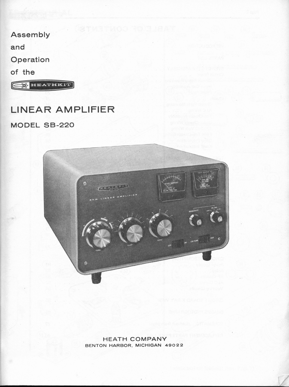
INTRODUCTION
The Heathkit Model
SP-220
Linear Amplifier
is
e
completely self-contained, table top, grounded grid, linear
amplifier.
It
is
designed tooperate at the maximumamateur
power limit on
SSB,
CW, and RTTY.
Its
stylingmatchesthe
Heath
SB
series of amateur equipment.
The Amplifier
is
designed to
be
used with exciters which
deliver
100
watts
or
more output.
It
can
be
used with less
drivingpower, butwill givealower output.
A
broad-band, tuned input circuit for each band feeds the
two Eimac
3-5002
triode tubes connected in grounded grid
configuration. The tubes are biased beyond cut-off in the
receive1 mode, and zener-regulated bias controlsthe idling
current in thetransmitmode. The tubes arecooled by afan.
An ALC circuit develops negative voltage to be fed back to
the exciter to reduce
its
gain when the Amplifier
is
overdriven.
The antenna change-over relay
is
normally actuated by
exciter relay contacts to place the Amplifier inthe transmit
mode.
The Amplifier can be operatedfrom either
120
VACor
240
VAC
50/60
Hz lines and can be easily changed from one to
the other. Operation from a
240
volt line is recommended.
Each side of the line cord
is
equipped withacircuit breaker
to protectagainstoverloads.
An important feature of this Amplifier is that
it
can be
tuned up at the one kilowatt limitand can then
be
switched
to operate on
SSB
at
two kilowatts
P.E.P.
input. As the
switching changes both the voltage and current tothe final
tubes, the impedance remains the same and no additional
adjustmentof tuned circuits
is
required.
The tubes are "instant heating" types, and transmission may
be
started as soon as the Amplifier
is
switched on (after
Here is
a
full legal-limitAmplifier that can take
its
placeon
your operating table and give you years of troublefree
pleasure. ThisAmplifier hasacommandingvoice.
Read the "Kit BuildersGuide" for complete informationon
unpacking, parts identification, tools, wiring, soldering, and
step-by-stepassernbly procedures.
v

PARTS PICTORIAL
BROWN
u
(continued on fold-outfrom
Page
7)


PARTS
LIST
This Parts List contains all of the partsused intheassembly To order replacement parts, refer to the "Replacement
of the kit. Some parts are packaged in envelopes with the PartsPrice List" and use the Parts Order Formfurnished.
part number of the contents printed onthe outside. Except
for
the
initial
parts
check,
retain
these
parts
in
their
Check each
part
against the following Parts List. The key
envelopesuntilthey are calledfor intheassembly steps. numbers correspond to the numbers on the Parts Pictorial
(fold-out from Pages
4
and
7).
KEY PART PARTS DESCRIPTION
No. No.
--
Per Kit KEY PART PARTS DESCRIPTION
No. No.
--
Per Kit
RESISTORS CAPACITORS
112
Watt
1 1-9
1-44
1-18
1-22
1-23
1-24
1-25
1-26
Other Resistors
2 1-8-1
1-38-1
1000
S2 (brown-black-red)
2200
S2.
(red-red-red)
5600
S2
(green-blue-red)
22
kS2 (red-red-orange)
27
kS2 (red-violet-orange)
33
kS2 (orange-orange-orange)
47
kS2 (yellow-violet-orange)
100
kS2 (brown-black-yellow)
68
kS2
1
watt (biuegray-orange)
4.7
MS2
1
watt (yellow-violet-
green)
.82
S2
wire-wound
2
watt (gray-
red-silver)(same sizeas
1
watt),
5%
1
S2 wire-wound,
5
watt,
1%
3600
$2 wire-wound,
5
watt,
1
%
30
kS2 film,
7
watt
Molded
Mica
5 20-3
6 20-123
Mica
7 20-99
20-124
20-103
20-105
20-120
20-116
20-113
20-107
Disc
8 21-79
9 21-14
21-70
21-31
200
pF (red-black-brown)
500
pF
(.0005
pF)
.001
pF
6
kV
.001
pF
500
volt
.O1
pF
1.4
kV
.02
pF
500
volt

Page 6
KEY PART PARTS
No. No.
--
Per Kit
Other Capacitors
10 2i-28
I
CONTROLS-SWITCHES
DESCRIPTION
10 pF (10MMF or 10pyF)
tubular ceramic
,001 pF (1000MMFD)
6 kV, ceramic
20 yF (MFD)electrolytic
200 yF (MFD) electrolytic
437-437 pF ganged
variable, 2-section
250 pF variable
100kS2 control
DPST rocker switch
DPDT rocker switch
3-positionrotary switch
5-positionrotary switch
Rotary switch wafer
Circuit breaker
TPDT 110VDC relay
COILS-CHOKES-TRANSFORMERS
80120 plate coil
10115-meterinput coil
20-meter input coil
40-meter input coil
80-meter input coil
15/10 plate coil
Parasitic choke
1 mH RF choke
8.5 pH RF choke
9 pH RF choke
50 uH RF choke
Highvoltage transformer
Filament and bias transformer
DIODES-TUBES
33 56-24 1 1N458 silicon diode (yellow-
green-gray
)
34 56-26 1 1N191 germanium diode
(brown-white-brown)
35 56-82
1
1N3996A zener diode, 5.1V,
10watt, wlmounting hardware
36 57-27 15 Silicon diode
37 411-245 2 3-5002tube
KEY PART PARTS DESCRIPTION
No. No.
--
Per Kit
INSULATORS-GROMMETS-TERMINAL STRIPS-
CONNECTORS
38 71-2 1 Ceramic feedthrough insulator
(disassembled inbag)
39 73-4 1 5116" grommet
73-3 4 112" grommet
73-2 1 314" grommet
40 75-123
1
Linecord strain relief
75-124 1 6" x 4-112" fish paper
insulator
41 75-125 8 Capacitor mounting insulator
42 255-39 1 6-32x 1-114" tapped
phenolic spacer
43 255-42 3 6-32x 314" tapped phenolic
spacer
44 431-14
1
2-lugterminal strip
45 431-10 3 3-lugterminal strip
46 43142
1
5-lugterminal strip
47 431-20 1 6-lug terminal strip
48 431-13 1 4-screwterminal strip
49 432-137 6 Connector tab (large)
kXA3S66
L/'c-51-^-42memW
@mat
I)
'-.
51 43442 2 Phonosocket
52 434-93 2 5-lugceramic tube socket
53 436-5 2 Coaxial jack
54 438-9 1 Coaxial plug
55 438-12 1 Coaxial plug insert
WIRE-CABLE-SLEEVING
89-40 1 Line cord
134-36 2 Phonocable assembly
340-1 1 Barewire
343-2 1 Coaxial cable, RG-58AlU
343-8 1 Coaxial cable, RG-8lU
344-2 1 Small black strandedwire
344-7 1 Large black strandedwire
344-13 1 Blue hookupwire
344-50 1 Black hookupwire
344-51 1 Brown hookup wire
344-52 1 Red hookup wire
344-53 1 Orange hookup wire
344-54 1 Yellow hookupwire
344-55 1 Green hookup wire
,
344-56 1 Blue hookupwire (thick
insulation)
345-1 1 Large metal braid
345-2 1 Small metal braid
346-4 1 Black sleeving
346-7 2 Clear sleeving (large)
346-29
1
Clear sleeving (small)
56 354-5 6 Cable tie

Page
7
KEY PART
No. No.
--
HARDWARE
#6
Hardware
57 250-138
58 250-56
59 250-416
60 250-8
61 250-32
62 250-89
63 250-218
64 250-206
65 250-40
66 250-47
67 252-3
68 253-1
69 253-2
70 254-1'
71 255-71
PARTS
Per Kit
#8
Hardware
74 250-43
75 250-137
76 2524
77 254-2
78 25566
79 259-2
#10
Hardware
80 250-188
81 252-30
82 252-31
83 254-3
Other
Hardware
84 207-8
85 250-213
86 252-15
87 252-7
88 252-10
89 253-10
90 253-42
91 253-19
92 254-4
93 254-9
94
259-25
DESCRIPTION
6-32x 3/16"
screw
6-32x 114"
binderheadscrew
6-32
x
114"
flat head screw
#6 x 318"
sheet metalscrew
6-32x 318"
flat head screw
6-32x 318"
binderhead screw
6-32x 318"
phillipshead screw
6-32x
1
1116"
screw
6-32x 1-112"
screw
6-32x 2"
screw
6-32
nut
#6
fiber flatwasher
#6
fiber shoulder washer
#6
lockwasher
6-32x 3/4"
tapped :metal
spacer
6-32x 1-118"
tappedspacer
#6
solder lug
8-32x 114"
setscrew
8-32x 318"
screw
832
nut
#8
lockwasher
8-32.x1-318"
spacer
#8
solder lug
10-24
x
1
"
round head screw
10-24
riut
10-24
wing nut
#10
lockwasher
Cable damp
440x 5/16"
screw
440
nut
Control nut
Speednut
Control flatwasher
112"
flatwasher
314"
flatwasher
Control lockwasher
#5
lockwasher
#10
double lug
KEY PART PARTS DESCRIPTION
No. No.
--
Per Kit
Other Hardware(cont'd.)
95 258-115
1
Brass spring
518" x 5112"
96
25410 1
Control solder lug
97 25424 1
Longsolder lug
98 260-12 2
Plateconnector
99 456-16 1
Shaftcoupler
METAL PARTS
MISCELLANEOUS
Cabinet
Chassis.
.
Capacitorbank bracket
Front panel
Rear panel
Leftside panel
Right side panel
Angle bracket
Platecoil bracket
Top rear platecover
Perforatedtopcover
Perforatedfancover
RF shield
Coil mountingshield
Silver platedstrip
Printedcircuit board
Black tapered spacer
Rubberfoot
Fan blade
Siliconegrease
Plateamperes meter
Multi-meter
Fan motor
Phenolicshaft
Small knob
Largeknob'
Danger highvoltagelabel
Nameplate
Blueand white label
Nutstarter
PartsOrder Form
KitBuildersGuide
Manual
(See
front cover
for
partnumber.)
,
Solder

PARTS PICTORIAL
(cont'd.)

Page
8
pre
b=~----=*-l&g
STEP-BY-STEP ASSEMBLY
Before starting to assemble this kit, read the "Kit Builders
Guide" for complete information on wiring, soldering, and
step-by-stepassembly procedures.
The illustrations in this section of the Manual are called
Pictorials and Details. Pictorialsshow the overall operation
for
a
group of assembly steps; Detailsare used inadditionto
the Pictorials to illustrate
a
single step. When you are
directed to refer to a certain Pictorial "for the following
steps," continueusingthat Pictorial untilyou are referred to
another Pictorialfor another group of steps.
86 through 89) from time totime to setheactual positions
of wires and components.
Lockwashers and nuts will be used with most screws when
mounting parts, unless the assembly steps state otherwise.
Consequently, the applicable stepswillcall out only the size
and type of hardware used. For example, the phrase "Use
6-32
x
114"
hardware" means to use
6-32
x
114"
screws, one
or more #6 lockwashers, and 6-32nuts. Refertothe Details
for the proper installationof hardware. Be sure to position
each part as shown in the Pictorials. Follow the instructions
carefully, and read the entire step before performing the
operation.
As
,the drawings in the Manual may be slightly distorted to When
a
step directsyou to "connect" an insulatedwire, first
show all the parts clearly, look at the Chassis Photos (Pages prepare
its
ends by removing
114"
of insulation.

Page
10
-k-J
CIRCUIT BOARD
Solder a part or group of parts only when directed. Use
112
On the circuit board, be especially careful not to cover
watt resistoks unless directed otherwise in a step. Each unused holes with solder or bridge solder acrossfoilsduring
resistor will be called out by the resistance value (in
a,
kQ,
assembly. Perform thesteps inPictorial
1-1.
or
MQ)
and color code. Capacitors will becalled out bythe
capacitance value and type.
START
FOR GOOD SOLDERED
CONNECTIONS. YOU MUST
KEEP THE SOLDERING
IRON TIP CLEAN..
WIPE IT OFTEN WlTH
A
DAMP SPONGE OR CLOTH.
NOTE: DIODES MAY BE SUPPLIED
I
N ANYOF THE FOLLOWING SHAPES.
THE
CATHODE
END
OF THE DIODE
IS MARKED WlTH A BAND OR
2ANDS. ALWAYS POSITION THIS
END AS SHOWN INTHE PICTORIAL.
(y/~ositionthe circuit board as
shown andinstalldiodes(#57-27)
at D7, D5, D3, Dl, D9, D11, and
D13. Make sure all seven cath-
ode banded ends are to the
({)
Solder.all leads to the foil and
cut off the excess lead lengths.
(dInstall diodes (#57-27) at D6,
D4, D2, D8, D10, D12, and Dl4
with their cathode ends to the
(
\/)
Solder all leads to the foil and
cut off the excess lead lengths.
(4
CAREFULLY INSPECT ALL
DIODES IN THE PRECEDING
STEPS TO BE SURE THEYARE
POSITIONED
AS
SHOWN IN
THE PICTORIAL AND ON THE
1
CIRCUIT BOARD.
CONTINUE
PICTORIAL
1-1

Page 11
~~=*~--*=*=~J
CIRCUIT BOARD PREWlRlNG
Refer to Pictorial 1-2for the following steps.
From the component side of the circuit board, insert one
NOTE:
To prepare lengths of hookup wire, as in the end of each of the following wires intothe designated hole.
following step, cut the wire to the indicated length and Solder each wire onthefoil side.
remove 114" of insulation from each end. If the wire is
solder to hold the strands together. Unlessotherwise stated,
V/
sranded, twist the ends tightly and apply amamountof
(
Connect a 5-114" length of red hookupwire to hole
A
inthe circuit board (S-1
).
"hookup wire" will mean the small solid-conductor wire
supplied invariouscolors.
(
d"
Connect a 3-314" length of black hookupwiretohole
B
onthe circuit board 6-1).
(
/
)
Preparethefollowing lengthsof hookupwire:
L.--
-
5-1
14"
red
3-314" black
6-112" black
17-112" small black strandedwire
7-112" orange
6-112" yellow
9-112" heavy blue (thick insulation)
I
2-314"'heavy blue (thick insulation)
(,/Connect a 6-112" length of black hookupwireto hole
Con the circuit board (S-1
1.
(
f
1
Connect a 17-112" length of black stranded wire to
hole
E
onthe circuit board 6-1).
Connect a 7-112" length of orange hookup wire to
hole
G
onthe circuit board 6-1).
(d
Connect
a
6-112'' length of yellow hookup wire to
hole
F
onthe circuit board (S-1).
(
J)
Connect a 9-112" lengthof heavy blue hookupwireto
hole
H
onthecircuit board 6-1).
(/Connect a 2-314" lengthof heavy blue hookupwireto
hole
J
onthe circuit board 6-1).
(./fTrim all excess lead lengths from the foil side of the
circuit board.
-2-314"
HEAVY
BLU
BLU
17-112" BLK--
STRANDED
PICTORIAL
1-2
RED-
BLK-
BLK-

Page
12
-*;--).-3
(
)
Carefully inspect the foil side of the circuit board;
all
lettered holes except
D
and
K
should be soldered.
Make sure there are no solder bridges between foils.
Also notethat one diode
is
not installed.
This completes the prewiring of the circuit board. Set
it
aside until called for later. Proceed with the "Input Coil
Assembly" section.
INPUT COIL ASSEMBLY
Refer to Pictorial
2-1
for thefollowingsteps.
Refer to Detail 2-1Afor the next two steps.
NOTE: A
plastic nut starter has been providedwiththis kit.
Use
it
to hold and start nuts on screws. See Page
3
of the
"Kit BuildersGuide" for more information.
PICTORIAL
2-1
Detail
2-1A

Page 13
INSIDE OF
COIL MOUNTING
n
SHIELD
LUG
1
LOCATING
LUG
LOCATING
SLOT
ING
IS
Detail
2-1C
Detail 2-18 shows the coil mounting locations for the
following steps. Notethat the locatinglugofeach
mil
must
be
positioned inthe locatingslot, and that each mil.must be
pushed into
its
mounting hole until the mountingears snap
outto holdthecoil inplaceas shown inDetail2-1C.
Detail
2-1B
(d
lnstall the 2ameter
mil
(#40965) at CV.
See
Detail
2-1C.
/
( )
Installthree #6 solder lugsonthe coil mountingshield
(4
Install
a
10115-metercoil
(#40-964)
at CX.
(#206-457)
at
CLwith 6-32x 318" hardware. Position
the lugsas shown inDetail2-1
0.
(4
Installa 10115-meter
mil
(#40-964)
at CY.
(d
Installthe 8hetercoil (#40-1012) at
CS.
;
(d
Installa
#6
solder lug at DFwitha6-32
x
1/4"&rew
and a6-32nut. Formthe solder lugas shown.
(d
Installthe40meter
mil
(#40-966) at CT.
(4
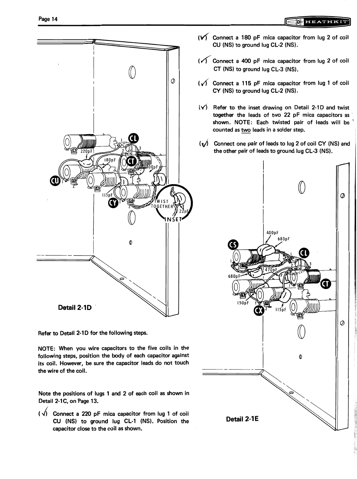
Connect a
180
pF mica capacitor from lug
2
of coil
CU
(NS)toground lug
CL-2
(NS).
Detail
2-1D
'
Refer toDetail
2-1
Dfor thefollowingsteps.
NOTE: When you wire capacitors to the five coils in the
following steps, position the body of each capacitor against
its
coil. However, be sure the capacitor leads do not touch
thewireof the coil.
(/(Connect a
400
pF mica capacitor from lug
2
of coil
CT
(NS) toground lug
CL-3
(NS).
(
d
Connect a
115
pF mica capacitor from lug
1
of coil
CY
(NS)toground lug
CL-2
(NS).
(4
Refer to the inset drawing on Detail
2-ID
and twist
together the leads of
two
22
pF mica capacitors as
shown. NOTE: Each twisted pair of leads will be
'
countedas leads inasolder step.
I
('t/j
Connect one pair of leads to lug
2
of coil
CY
(NS) and
theother pairof leadstoground lug
CL-3
(NS).
Notethe positionsof lugs
1
and
2
of each coil as shown in
Detail
2-1C,
on Page
13.
(
d
Connect a
220
pF mica capacitor from lug
1
of coil
CU
(NS) to ground lug
CL-1
(NS). Position the
capacitor closetothe coil as shown.
Page
15
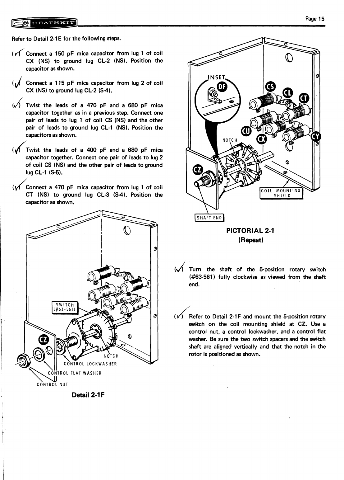
Refer to Detail 2-1
E
for thefollowing steps.
(
Jf
Connect a
150
pF mica capacitor from lug
1
of coil
CX
(NS)
to ground lug CL-2
(NS).
Position the
capacitor as shown.
(4
Connect a 115 pF mica capacitor from lug
2
of coil
CX
(NS)
toground lug CL-2
(S-4).
Id
Twist the leads of a
470
pF and a
680
pF mica
capacitor together as in a previous Rep. Connect one
pair of leads to lug
1
of coil
CS
(NS)
and the other
pair of leads to ground lug CL-1
(NS).
Position the
capacitorsas shown.
(4Twist the leads of a
400
pF and a
680
pF mica
capacitor together. Connect one pair of leads to lug
2
of coil
CS
(NS)
and the other pair of leads toground
lug CL-1
6-5).
(y/Connect
a
470
pF mica capacitor from lug
1
of coil
CT
(NS)
to ground lug CL-3
(S-4).
Position the
capacitoras shown.
PICTORIAL
2-1
(Repeat)
(d
Turn the shaft of the bposition rotary switch
(#63-561)
fully clockwise as viewed from the shaft
end.
J
(
)
Refer to Detail
2-IF
and mount the 5-position rotary
switch on the coil mounting shield at CZ. Use a
control nut, a control lockwasher, and acontrol flat
washer. Be sure the two switchspacers and the switch
shaft are aligned vertically and that the notch in the
rotor
is
positionedas shown.
CONTROL
FLAT
WASHER
\\
Detail
2-1
F
Page
16
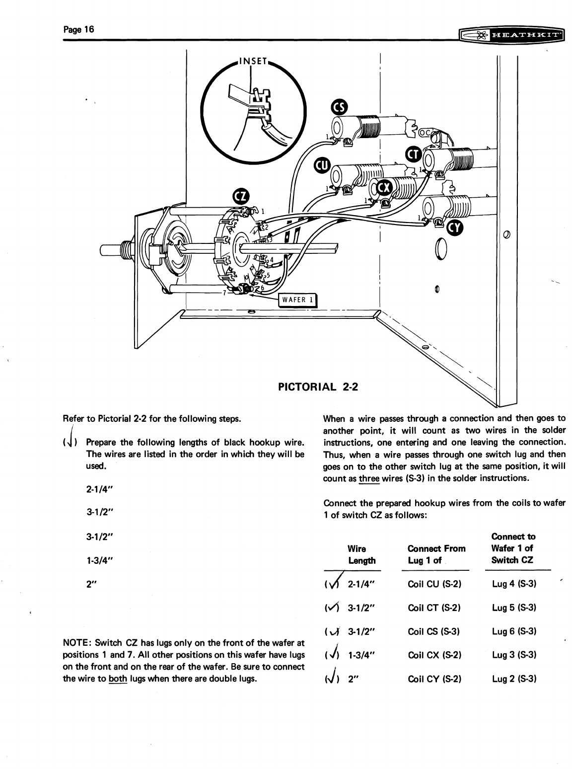
Refer to Pictorial
2-2
for thefollowing Reps. When a wire passes through a connection and then goes to
another point,
it
will count as two wires in the solder
1
Prepare the following lengths of black hookup wire. instructions, one entering and one leaving the connection.
The wires are listed in the order inwhich theywill be Thus, when a wire passes through one switch lug and then
used. goes on to the other switch lug at the same position,
it
will
countas
three
wires
6-3)
inthesolder instructions.
2-114"
Connect the prepared hookupwires from the coilstowafer
1
of switch CZ as follows:
Connect
to
Wire Connect
From
Wafer
1
of
Length Lug
1
of
Switch
CZ
IV/2-1/4"
Coil
cu
(s-2)
Lug
4 6-31
(4
3-112"
Coil CT
(S-2)
Lug
5
(S-31
(4
3-112"
Coil
CS
6-31
Lug
6
6-31
NOTE: Switch CZ has lugsonly on thefront of thewafer
at
positions
1
and
7.
All other positionson this wafer have lugs
(
j)
13/4"
Coil CX
(S21
Lug
3 631
on thefront and on the rear of thewafer. Be sure toconnect
thewire to
@
lugswhen thereare double lugs.
(1
2"
Coil CY
6-21
Lug
2 6-31
Table of contents


