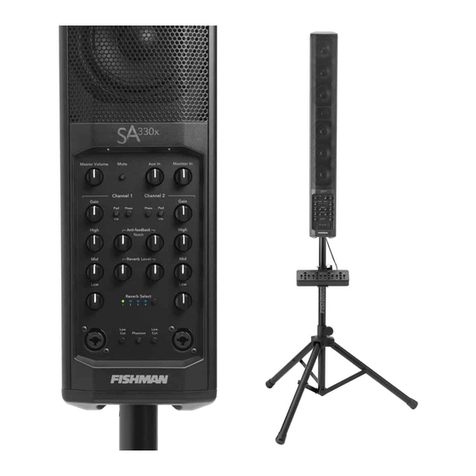
Heco Ascada 600 TOWER Quick start guide

ASCADA 600 TOWER
Wichtige Hinweise zur Installation / Garantieurkunde
Important notes for installation / warranty card
Mode d’emploi / certicat de garantie
Avvertenze importanti per l’installazione / certifcato di garanzia
Notas importantes sobre la instalación / certicado de garantía
/

Bitte führen Sie das Gerät am Ende seiner Lebensdauer den zur Verfügung stehenden Rückgabe-
und Sammelsystemen zu.
At the end of the product’s useful life, please dispose of it at appropriate collection points provided
in your country.
Une fois le produit en n de vie, veuillez le déposer dans un point de recyclage approprié.
© 2013 CSR plc and its group companies.
The aptX® mark and the aptX logo are trade marks of CSR plc or one of its group companies and
may be registered in one or more jurisdictions.
The
Bluetooth
® word mark and logos are registered trademarks owned by Bluetooth SIG, Inc.
and any use of such marks by Heco is under license. Other trademarks and trade names are
those of their respective owners.
KONFORMITÄTSERKLÄRUNG
Hiermit erklärt die Firma Magnat Audio-Produkte GmbH, dass sich das Gerät Heco Ascada 600
Tower in Übereinstimmung mit den grundlegenden Anforderungen und anderen relevanten
Vorschriften der Richtlinie 1999/5/EG befindet. Die Konformitätserklärung finden Sie unter www.
heco-audio.de im Downloadbereich des Gerätes.
Declaration of conformity
Hereby, Magnat Audio-Produkte GmbH declares that the Heco Ascada 600 Tower is in compliance
with the essential requirements and other relevant provisions of directive 1999/5/EC. The Declaration
of Conformity can be found at http://www.heco-audio.de in the download area of the device.
DÉCLARATION DE CONFORMITÉ
Magnat Audio-Produkte GmbH déclarons que le produit Heco Ascada 600 Tower est conforme aux
exigences essentielles et aux autres dispositions pertinentes de la Directive 1999/5/EC. Une copie
de la Déclaration de conformité est disponible à l‘adresse http://www.heco-audio.de (espace de
téléchargement du produit).

45
Abbildungen/Illustrations
4
10
17
24
31
38

4
Sehr geehrter HECO-Kunde,
vielen Dank dafür, dass Sie sich für ein HECO-Produkt entschieden haben. Wir möchten Ihnen hierzu von unserer Seite
recht herzlich gratulieren. Durch Ihre kluge Wahl sind Sie Besitzer eines Qualitätsproduktes geworden, das weltweite
Anerkennung ndet.
WICHTIGE SICHERHEITSHINWEISE:
Bitte lesen Sie die Bedienungsanleitung vor der Inbetriebnahme aufmerksam durch. Die Bedienungsanleitung
enthält wichtige Hinweise zum Betrieb und zur Sicherheit. Befolgen Sie unbedingt alle Hinweise. Bewahren Sie
die Bedienungsanleitung gut auf.
• WARNHINWEISE: Alle Warnzeichen auf den Lautsprechern, dem Zubehör und in der Bedienungsanleitung müssen
beachtet werden.
• WÄRMEEINWIRKUNG: Betreiben Sie die Lautsprecher mit Zubehör nur im Temperaturbereich von 0°C bis 40°C.
• Die Lautsprecher sollen nicht in der Nähe von Wärmequellen aufgestellt werden (Heizkörper, Öfen, Heizstrahler,
offene Flammen). Beim Aufstellen in Nähe von Verstärken sollte ein Mindestabstand von 10 cm nicht unterschritten
werden.
• EINFLUSS VON FEUCHTIGKEIT: Die Lautsprecher dürfen nicht Tropf- oder Spritzwasser ausgesetzt werden. Ebenfalls
dürfen sie nicht zum Abstellen von Vasen oder anderen mit Feuchtigkeit gefüllten Behältern benutzt werden. Setzen
Sie die Lautsprecher weder Wasser noch hoher Luftfeuchtigkeit aus. Es besteht die Gefahr eines Stromschlags. Bei
Kontakt mit Feuchtigkeit oder Flüssigkeiten sofort den Netzstecker ziehen.
• FREMDKÖRPER: Achten Sie darauf, dass keine Fremdkörper durch die Öffnungen des Lautsprechers ins Innere
gelangen. Sie könnten Kurzschlüsse auslösen und auch einen Stromschlag und Brand.
• REINIGUNG: Bitte verwenden Sie ein trockenes und weiches Tuch und keine Reinigungsmittel, Sprays oder
chemische Lösungsmittel, da sonst die Oberäche beschädigt werden könnte.
• STROMANSCHLUSS: Bitte beachten Sie die Spannungswerte auf dem Hinweisschild. Das Netzteil der Lautsprecher
darf nur mit den angegeben Spannungswerten und Frequenzwerten betrieben werden.
• BLITZSCHUTZ/VORSICHTSMASSNAHMEN: Wird das Gerät längere Zeit (z.B. im Urlaub) nicht benutzt, sollte es
durch Ziehen des Netzsteckers vom Netz getrennt werden. Das Gerät sollte auch bei Gewitter vom Netz getrennt
werden. Somit wird eine Beschädigung durch Blitzschlag und Überspannung verhindert.
• NETZKABEL: Das Netzkabel muss immer betriebsbereit sein und sollte nur so verlegt sein, dass niemand auf das
Netzkabel treten kann. Auch darf es nicht durch Gegenstände eingeklemmt sein, die das Kabel beschädigen können.
Bei Verwendung von Steckern und Mehrfachsteckdosen ist darauf zu achten, dass das Kabel an der Stelle, wo es aus
der Steckdose kommt, nicht geknickt wird. Das Netzkabel nicht mit feuchten Händen anschließen oder entfernen.
• ÜBERLASTUNG: Steckdosen, Mehrfachsteckdosen und Verlängerungskabel sollten nicht überlastet werden. Bei
Überlastung besteht Stromschlag- und Brandgefahr.
• Die Lautsprecher sollten nur auf festem Untergrund und nicht auf bewegliche Untergestelle gestellt oder montiert
werden, da sonst Verletzungsgefahr besteht.
SCHÄDEN, DIE VOM FACHMANN BEHOBEN WERDEN MÜSSEN:
Bei den folgenden Schäden sollte der Lautsprecher sofort vom Netz getrennt werden und ein Fachmann mit der
Reparatur beauftragt werden:
- Beschädigungen des Netzkabels oder Netzsteckers.
Ein beschädigtes Kabel darf nicht repariert, sondern muss komplett ausgetauscht werden.
- Wenn Feuchtigkeit oder Wasser in das Gerät gelangt ist oder Gegenstände in das Gerät gefallen sind.
- Wenn der Lautsprecher heruntergefallen ist und das Gehäuse beschädigt ist.
- Wenn das Gerät nicht richtig funktioniert, obwohl man alle Hinweise in der Bedienungsanleitung beachtet hat.
Es dürfen nur nachträgliche Änderungen vorgenommen werden, die vom Hersteller genehmigt sind.
Es dürfen zur Reparatur nur Originalersatzteile verwendet werden.
Nach einer Reparatur sollte das Gerät auf Sicherheit überprüft werden, um eine ordnungsgemäße und sichere Funktion
sicherzustellen.
Reparaturen müssen immer qualizierten Fachkräften überlassen werden, da man sich sonst gefährlichen
Hochspannungen oder anderen Gefahren aussetzt.
Das Dreieck mit Blitzsymbol warnt den Benutzer, dass innerhalb des Gerätes hohe Spannungen verwendet
werden, die gefährliche Stromschläge verursachen können.
Das Dreieck mit Ausrufezeichen macht den Benutzer darauf aufmerksam, dass in der beigefügten
Bedienungsanleitung wichtige Betriebs- und Wartungsanweisungen (Reparatur) enthalten sind, die unbedingt
beachtet werden müssen.

5
Nicht öffnen! Gefahr des elektrischen Schlages!
ACHTUNG: Weder das Gehäuse/Netzteile öffnen noch Abdeckungen entfernen, um
Stromschläge zu vermeiden. Keine Reparatur durch den Benutzer. Reparatur nur durch
qualizierte Techniker! Keine Steckdosen oder Verlängerungskabel benutzen, die den Stecker
des Gerätes nicht vollständig aufnehmen.
ENTSORGUNGSHINWEISE
Gemäß der europäischen Richtlinie 2002/96/EC müssen alle elektrischen und elektronischen Geräte über lokale
Sammelstellen getrennt entsorgt werden. Bitte beachten Sie die lokalen Vorschriften, und entsorgen Sie Ihre Altgeräte
nicht mit dem normalen Hausmüll.
BATTERIE-ENTSORGUNG
Alt-Batterien sind Sondermüll und müssen gemäß den aktuellen Vorschriften entsorgt werden.
INHALT:
(A) 1 Stk. Aktivlautsprecher rechts (Master)
(B) 1 Stk. Aktivlautsprecher links (Slave)
(C) 2 Stk. Netzkabel für die Aktivlautsprecher
(D) 1 Stk. Fernbedienung einschließlich Batterie (Knopfzelle CR2025)
(E) 1 Stk. XLR-Kabel (5m)
(F) 1 Stk. USB-Kabel (1.8m)
(G) 2 Stk. Bodenplatten
(H) 2 Sätze Befestigungsschrauben für Bodenplatten incl. Innensechskantschlüssel
(I) 1 St. Bedienungsanleitung (einschl. Garantieurkunde)
AUSPACKEN DES LAUTSPRECHERSETS
Bitte die Lautsprecher und das Zubehör vorsichtig auspacken und den Inhalt des Originalkartons anhand der Liste
oben überprüfen. Im Falle eines Transportschadens wenden Sie sich bitte an Ihren Lieferanten. Bewahren Sie das
Verpackungsmaterial gut auf. Die Originalverpackung ermöglicht bei einem späteren Umzug und im Servicefall einen
problemlosen Transport.
MONTAGE DER BODENPLATTEN
An beiden Lautsprechern müssen vor dem Betrieb die im Lieferumfang enthaltenen Bodenplatten montiert werden.
Stellen Sie hierzu die Lautsprecher mit der Unterseite nach oben auf eine saubere und stabile Unterlage. Am besten
entfernen Sie den Schutzbeutel erst nach der Montage vollständig, um Beschädigungen der Lackoberäche zu
vermeiden.
Montieren Sie nun die Bodenplatte mit den beigelegten M6-Innensechskantschrauben wie in Bild 1 dargestellt. In die
Gewindeeinsätze der Bodenplatten können wahlweise Gummi-Füße oder Metall-Spikes eingeschraubt werden. Von
beiden sind jeweils 8 Stück im Lieferumfang enthalten.
BEDIENUNGSELEMENTE RECHTER LAUTSPRECHER (MASTER), FRONT (ABB. 2)
(1) STBY/POWER:
•Rot:Stand-By-Modus
•Weiß:Betriebsmodus
(2) Zustandsanzeige Funkverbindung rechte – linke Box:
•langsamblinkend:Verbindungsaufbau
•dauerhaftleuchtend:Verbindunghergestellt
•aus:KeineFunkverbindung,SignalübertragungüberKabel
(3) LED Display:
Das zweistellige Display zeigt den gewählten Eingang und Informationen über den Betriebszustand an
• Eingänge:
BT: Bluetooth - Eingang Die Anzeige blinkt während Verbindungsaufbau / im Pairing-Modus.
OP: Optischer Digitaleingang
CO: Coaxialer Digitaleingang
UB: USB-Audio Eingang
AX: Analoger Eingang

6
•Lautstärkeanzeige:BeiVeränderungderLautstärkewirdderaktuelleWert(0…40)angezeigt.WenndieWiedergabe
stummgeschaltet ist (Mute), blinkt der aktuelle Wert.
•TD:Derrechte(Master-)LautsprecherkonntekeineFunkverbindungzumlinken(Slave-)Lautsprecheraufbauen.
•TC:AnzeigeblinktwährendAufbauderkabellosenAudioverbindungzwischenrechtemundlinkemLautsprecher.
•DieAnzeigeerlischtca.10sec.nachderletztenBedienung.
(4) Fernbedienungssensor: zielen Sie mit der Fernbedienung stets auf diese Stelle am rechten (Master-) Lautsprecher.
BEDIENUNGSELEMENTE RECHTER LAUTSPRECHER (MASTER), RÜCKSEITE OBEN (ABB. 3)
(7) Dreh-/Drückregler zur Quellenwahl (Drücken) und Einstellung der Lautstärke (Drehen). Benden sich die Lautsprecher
im Standby Modus, können sie über die Druckfunktion eingeschaltet werden.
(8) Regler zur Anhebung / Absenkung des Basspegels
(9) Regler zur Anhebung / Absenkung des Hochtonpegels
BEDIENUNGSELEMENTE RECHTER LAUTSPRECHER (MASTER), RÜCKSEITE UNTEN (ABB. 4)
(10) Power-Schalter
(11) Netzspannungswahlschalter
(12) Netzanschluss
(13) Sicherung
(14) USB-Ladeausgang
(15) USB-Eingang Stereo
(16) optischer Digitaleingang
(17) koaxialer Digitaleingang
(18) Stereo-Eingang (Cinchbuchsen)
(19) Ausgang zum Anschluss eines aktiven Subwoofers
(20) Anschluss für den linken Lautsprecher über das mitgelieferte XLR-Kabel
(21) Pairing Taste Funkverbindung links - rechts
BEDIENUNGSELEMENTE LINKER LAUTSPRECHER (SLAVE), FRONT (ABB. 2)
(5) STBY/POWER:
•Rot:Stand-By-Modus
•Weiß:Betriebsmodus
(6) Zustandsanzeige Funkverbindung rechte – linke Box:
•langsamblinkend:Verbindungsaufbau
•dauerhaftleuchtend:Verbindunghergestellt
•aus:KeineFunkverbindung,SignalübertragungüberKabel
BEDIENUNGSELEMENTE LINKER LAUTSPRECHER (SLAVE), RÜCKSEITE UNTEN (ABB. 5)
(22) Power-Schalter
(23) Netzspannungswahlschalter
(24) Netzanschluss
(25) Sicherung
(26) Anschluss für den rechten Lautsprecher über das mitgelieferte XLR-Kabel
(27) Pairing Taste Funkverbindung links - rechts
ACHTUNG:
Da es sich um einen Lautsprecher mit eingebautem Verstärker handelt, muss dieser über das beiliegende Netzkabel an
die Netzleitung angeschlossen werden. Der Netzspannungswahlschalter (11) ist ab Werk auf 230 V für die Verwendung
im europäischen Raum eingestellt.
Sehr wichtig: Wird der Lautsprecher in 120 V-Stellung an das 230 V Netz angeschlossen, führt dies zwangsläug
zur Zerstörung des eingebauten Verstärkers!

7
BEDIENUNG MIT DER SYSTEM-FERNBEDIENUNG (ABB. 6)
BITTE BEACHTEN SIE: Nur der rechte Lautsprecher (Master) besitzt einen Fernbedienungssensor (siehe Abb. 2, (4)).
Zielen Sie also stets auf diese Stelle.
(28)ON/STBY:Schaltet die Lautsprecher ein, wenn sie sich im Standby-Modus benden. Der rechte (Master-)
Lautsprecher schaltet den linken (Slave-) Lautsprecher automatisch mit ein und aus. Leuchten die Stand-by LEDs (Abb.
2, (1) und (5)) nicht, müssen Sie die Netzschalter der Lautsprecher (Abb. 4, (10), Abb. 5, (22)) einschalten. Umgekehrt
können die Lautsprecher vom Power-Betrieb auf Standby geschaltet werden.
(29)AUX: Schaltet das Gerät auf den analogen Stereoeingang um. Im Display wird AX angezeigt.
(30)COAX:Schaltet das Gerät auf den digitalen Koaxialeingang um. Im Display wird CO angezeigt.
(31) OPT:Schaltet das Gerät auf den optischen Koaxialeingang um. Im Display wird OP angezeigt.
(32)USB:Schaltet das Gerät auf den USB-Eingang um. Im Display wird UB angezeigt.
(33)BT:Schaltet das Gerät auf den Bluetootheingang um. Im Display wird BT angezeigt.
(34)PAIR:Schaltet das Gerät bei Bluetooth-Betrieb in den Pairing-Modus, um Kopplung zu einem Bluetooth-Quellgerät
herzustellen. Die Display-Anzeige BT blinkt schnell.
(35, 36) VOLUME: Erhöht (+) oder verringert (-) die Lautstärke.
(37)MUTE:Schaltet den Ton stumm und wieder ein.
(38)PLAY/PAUSE: Pausiert den aktuell abgespielten Titel eines Bluetooth-Quellegeräts bzw. setzt die Wiedergabe fort.
(39)TITELSPRUNG ZURÜCK: Einmaliges Drücken startet den aktuell abgespielten Titel eines Bluetooth-Quellgeräts
von vorne. Durch mehrmaliges Drücken springt das Quellgerät zu vorherigen Titeln.
(40)TITELSPRUNG VOR: Einmaliges Drücken startet den nächsten Titel eines Bluetooth-Quellgeräts. Durch
mehrmaliges Drücken springt das Quellgerät zu folgenden Titeln.
BITTE BEACHTEN SIE: Die Steuerungsfunktionen für Bluetooth-Geräte über die Tasten 38, 39 und 40 unterliegen aus
technischen Gründen einer kurzen Reaktionsverzögerung. Zudem sind die Funktionen der Steuerung vom individuellen
Bluetooth-Quellgerät abhängig.
ANSCHLIESSEN DES HECO ASCADA 600 TOWER
Audioverbindung zwischen rechtem Lautsprecher (Master) und linkem Lautsprecher (Slave):
1. Kabellose Verbindung über “Point to point“ Bluetooth mit aptX®. Dies ermöglicht ein komplett kabelloses Stereo-
Setup (außer Stromkabel) und damit besonders hohen Komfort. Durch die hochwertige Funkverbindung in CD-Qualität
entstehen keine Einbußen beim Klang.
Bei der Erst-Inbetriebnahme muss diese Verbindung einmal eingerichtet werden:
Schalten Sie bei beiden Lautsprechern den Netzschalter ein, beide Lautsprecher benden sich nun im Standby Modus,
die Betriebs-LEDs leuchten rot. Schalten sie nun den rechten (Master-) Lautsprecher per Fernbedienung (Abb. 3, (7))
oder an den rückseitigen Bedienungselementen (Abb. 4, (10)) ein. Um das Pairing einzuleiten, drücken Sie die Pairing-
Taste am linken (Slave-) Lautsprecher. Dies schaltet den linken (Slave-) Lautsprecher ein und aktiviert seine Pairing-
Funktion, die Funkverbindungs-LED (Abb. 2, (6)) blinkt schnell. Drücken Sie danach die Pairing-Taste am rechten (Master-)
Lautsprecher, die Funkverbindungs-LED (Abb. 2, (2)) blinkt schnell. Nach kurzer Zeit verbinden sich die Lautsprecher,
die beiden LEDs leuchten jetzt durchgehend blau. Das Lautsprecherset ist nun betriebsbereit. Dieser Vorgang muss nur
einmal durchgeführt werden, danach erfolgt die Verbindung bei jedem Einschalten automatisch.
Bitte beachten Sie, dass bei der Funkverbindung technisch bedingt das Audiosignal leicht verzögert wiedergegeben
wird. Bei reiner Audioanwendung ist das jedoch irrelevant.
2. Verbindung mittels XLR-Audiokabel
Wenn Sie die Lautsprecher auch in Verbindung mit Video-Inhalten nutzen möchten (z.B. Wiedergabe von Fernsehton),
sollten die Lautsprecher mit einem XLR-Kabel verbunden werden, um eine lippensynchrone Wiedergabe zu
gewährleisten. Hierzu verbinden Sie die Buchsen der rechten (Abb 4, (20)) und linken Box (Abb 5, (26)) mit dem im
Lieferumfang enthaltenen XLR-Kabel. Beide Lautsprecher sollten dabei ausgeschaltet sein. Sollte das Kabel zu kurz
sein, kann es durch ein hochwertiges XLR-Kabel mit der benötigten Länge ausgetauscht werden.
ANSCHLIESSEN DER STROMVERSORGUNG DER AKTIVLAUTSPRECHER
Zum Lieferumfang gehören zwei Netzkabel für die beiden Standlautsprecher. Das in Ihrem Land verwendete Netzkabel
könnte jedoch anders sein. Falls das Netzkabel nicht zu Ihren Steckdosen passen sollte oder Sie sich nicht sicher sind,
wenden Sie sich bitte an Ihren Heco-Fachhändler.
1. Stecken Sie die Netzkabel in die Buchsen (Abb. 4 (12)) bzw. (Abb. 5 (24)) am Verstärker des rechten bzw. linken
Lautsprechers.
2. Stecken Sie die Netzkabel jeweils in eine Steckdose. Achten Sie darauf, dass Sie den zur Steckdose passenden
Netzstecker verwenden (siehe Hinweis oben).

8
ANSCHLIESSEN VON TONQUELLEN AN DEN RECHTEN LAUTSPRECHER (MASTER)
BITTE BEACHTEN SIE: Nur der rechte (Master-) Lautsprecher kann mit Quellgeräten verbunden werden. Er reicht die
Signale für den linken Kanal automatisch an den linken (Slave-) Lautsprecher weiter. Der linke (Slave-) Lautsprecher
besitzt keinerlei Eingänge, welche für die Zuspielung genutzt werden können.
1. Anschluss an einen Vorverstärkerausgang/Verstärker/AV-Receiver
Schließen Sie den rechten Lautsprecher mit einem Stereo-Verbindungskabel an den Vorverstärkerausgang Ihres
Vorverstärkers/Verstärkers/AV-Receivers an.
2. Anschluss an einen Kopfhörerausgang oder Vorverstärkerausgang mit 3.5 mm Klinkenbuchse
Schließen Sie den rechten Lautsprecher mit einem Adapterkabel Stereo-Cinch auf 3,5-mm-Stereo-Klinke an den
Kopfhörerausgang Ihres Verstärkers, TV-Gerätes, MP3-Spielers, Smartphones etc. an.
3. Anschluss an einen Computer mit USB-Anschluss
Schließen Sie den rechten Lautsprecher mit dem USB-Kabel (Typ A auf Typ B, im Lieferumfang enthalten) an den
USB-Ausgang eines Computers an (siehe Bild 7). Ein Treiber wird nicht benötigt. Wenn in den Systemeinstellungen
oder der Audio-Software eine Auswahlmöglichkeit besteht, wählen Sie bitte die SPDIF-Schnittstelle
„Ascada 600 Tower“.
4. Anschluss an digitale Audioquellen
Schließen Sie den rechten Lautsprecher mit einem optischen oder koaxialen Digital-Audiokabel an den Digitalausgang
Ihres CD-Players/Computers/Spielekonsole/Netzwerkspielers an. Die Digitaleingänge können getrennt angewählt
werden, deshalb ist der gleichzeitige Anschluss zweier digitaler Quellen möglich.
BITTE BEACHTEN SIE: Die Digitaleingänge sind für Stereo-Signale bis 24Bit/96kHz geeignet
5. Verbindung mit einem Bluetooth-Quellgerät
Wählen Sie den Bluetooth-Eingang. Wenn vorher bereits eine Kopplung mit einem Bluetooth-Quellgerät bestand,
wird selbsttätig versucht, die Verbindung mit diesem Gerät wiederherzustellen. Dabei kann es vorkommen, dass Sie
die Wiederaufnahme der Verbindung am Quellgerät manuell bestätigen müssen.
Wenn keine vorherige Kopplung bestand oder die Verbindung nicht wiederhergestellt werden kann, aktivieren Sie
den Kopplungs-Modus, auch Pairing-Modus genannt. Um den Lautsprecher in den Pairing-Modus zu schalten,
drücken Sie kurz die Taste PAIR (Abb. 6, (34)) auf der Fernbedienung oder drücken und halten Sie den VOLUME/
SOURCE-Knopf (Abb. 3, (7)) für mindestens 3 Sekunden. Solange der Pairing-Modus aktiv ist, blinkt „BT“ im Display
(Abb. 2 (3)) schnell.
Schalten Sie nun den Bluetooth-Modus Ihres Quellgeräts ein. Der Lautsprecher wird in der Liste mit Bluetooth-
Geräten als „Ascada 600 Tower“ angezeigt. Falls er nicht in der Liste angezeigt wird, aktivieren Sie am Quellgerät
manuell die Suche nach Bluetooth-Geräten und stellen Sie sicher, dass sich der Lautsprcher im Pairing-Modus
bendet.
Je nach Quellgerät kann es vorkommen, dass während des Kopplungsvorgangs gefragt wird, ob das Passwort
angenommen werden soll. Das können Sie einfach mit „Annehmen“ bestätigen. Wenn weiterhin nach einem Passwort
gefragt wird, benutzen Sie die Standard-Passwörter „0000“ oder „1234“. Falls nach erfolgter Kopplung gefragt wird,
ob Sie eine Verbindung herstellen möchten, beantworten Sie dies ebenso mit „Ja“. Nach erfolgreicher Kopplung und
Verbindung hört die Display-Anzeige auf zu blinken.
Dieser Lautsprecher unterstützt den besonders hochwertigen Audio-Übertragungsstandard „aptx®“. Wenn Ihr
Quellgerät diese Technik ebenfalls unterstützt, wird beim Herstellen einer Bluetooth-Verbindung automatisch „aptx®“
als Übertragungsmodus gewählt.
BITTE BEACHTEN SIE: Bitte überprüfen Sie, ob der Ausgang der Tonquelle
a) einen festen Lautstärkepegel hat oder
b) der Pegel mit dem Lautstärkeregler der Tonquelle eingestellt werden ist.
Im Falle a) können Sie die Lautstärke mit der Fernbedienung des Heco Ascada 600 Tower einstellen,
im Falle b) sollte der Pegel der Tonquelle maximal so hoch eingestellt werden, dass bei höchster Lautstärkeeinstellung
der Ascada 600 Tower keine Verzerrungen zu hören sind. Die Lautstärke der Tonquelle ist ebenfalls zu beachten. Auch
hier dürfen keine Verzerrungen auftreten.
ANSCHLUSS EINES SUBWOOFERS AM RECHTEN LAUTSPRECHER (MASTER)
Der rechte (Master-) Lautsprecher hat auf der Rückseite einen Subwooferausgang (Abb. 3 (19)) zur Ansteuerung eines
aktiven Subwoofers. Benutzen Sie dazu ein Mono-Audiokabel und den LINE-IN-Eingang des Aktivsubwoofers. Der
Subwooferausgang verfügt über einen Tiefpass mit einer Grenzfrequenz von 150Hz. Ideal ist daher der Betrieb mit
einem Aktivsubwoofer mit variablem Tiefpass.

9
ANSCHLUSS EINES MOBILEN QUELLGERÄTS AM USB-LADEAUSGANG DES RECHTEN LAUTSPRECHERS
(MASTER)
Um ein Smartphone/Tablet/E-Book-Reader oder sonstige auadbare Geräte mit USB-Ladeeingang aufzuladen, können
diese mit einem passenden USB-Kabel an den USB-Ladeausgang (Abb. 4, (14)) angeschlossen werden.
BITTE BEACHTEN SIE: Es handelt sich ausschließlich um einen reinen Ladeausgang ohne jegliche Audiofunktionalität.
Eine unsachgemäße Benutzung (z.B. Versuch der Zuspielung mittels USB-Stick oder mobiler Festplatte) kann zu
Beschädigung oder Zerstörung der Geräte führen!
BEDIENUNG
Sobald beide Lautsprecher mit Strom versorgt sind, und beide Power-Schalter (Abb. 4, (10) und Abb.5(22)) eingeschaltet
sind, leuchten die Power-LEDs beider Lautsprechers rot (Abb 2 (1) und (5)). Die Lautsprecher benden sich dann im
Standby-Mode. Über die Eingänge am rechten Lautsprecher und über Bluetooth können insgesamt 5 verschiedene
Tonquellen gleichzeitig an das Lautsprecherset angeschlossen werden. Mittels der Fernbedienung (Abb. 6, (28)) werden
die Lautsprecher eingeschaltet und mit den Tasten (29) bis (33) eine Tonquelle ausgewählt. Die Lautstärke wird mittels
der Tasten (35) und (36) reguliert, mit Taste (37) kann der Lautsprecher stumm geschaltet werden.
Alternativ kann der Lautsprecher am hinteren Bedienpanel des rechten Lautsprechers (Abb. 3) bedient werden. Mit
dem ersten Drücken des VOLUME/SOURCE-Reglers (7) werden beide Lautsprecher eingeschaltet, weiteres Drücken
schaltet die Eingänge nacheinander durch. Durch das Drehen des Reglers wird die Lautstärke reguliert. Mit den Reglern
BASS (8) und TREBLE (9) können der Bass- und Hochtonpegel an die Aufstellung und den persönlichen Hörgeschmack
angepasst werden.
BITTE BEACHTEN SIE: Alle Heco-Lautsprecher sind auf bestmöglichen Klang abgestimmt, wenn sich die Klangregler
in Mittelstellung benden, d.h. bei linearer Wiedergabe des Verstärkers. Bei stark aufgedrehten Klangreglern wird dem
Tieftöner und dem Hochtöner vermehrt Energie zugeführt, was bei hohen Lautstärken zu deren Zerstörung führen kann.
Bitte achten Sie deshalb bei der Lautstärkeeinstellung auf Verzerrungen – und drehen Sie dann sofort leiser.
AUFSTELLUNGSHINWEISE
Die Ascada 600 Tower sollte nach Möglichkeit, leicht auf den Hörplatz angewinkelt, frei aufgestellt werden.
Die optimale Hörposition ist dann gegeben, wenn Lautsprecher und Hörplatz ein gleichschenkliges Dreieck bilden.
Durch die gleiche Entfernung des linken und rechten Lautsprechers zum Hörplatz werden die akustischen Signale
zeitrichtig wiedergegeben, und es entsteht ein natürliches, ausgewogenes Klangbild. Zwischen den Lautsprechern und
dem Hörplatz sollte Sichtverbindung bestehen. Schallabsorbierende oder reektierende Hindernisse verfälschen den
Klang.
ACHTUNG: Bei Eingriff in den Lautsprecher oder das Zubehör erlischt die Betriebserlaubnis. Zum Betrieb ist das
mitgelieferte Zubehör zu verwenden. Zusätzliches Zubehör muss für den Einsatzzweck vorgesehen und in einwandfreiem
Zustand sein.
TECHNISCHE DATEN:
Prinzip: Aktiver Stereo-Regallautsprecher
3-Wege Bassreex, vollaktiv
Lautsprecherbestückung: 3 x 125 mm Tieftöner,
1 x 125 mm Mitteltöner
1 x 25 mm Hochtonkalotte
Ausgangsleistung pro Lautsprecher: 110/220 Watt (RMS/Max.)
Gesamt-Ausgangsleistung: 220/440 Watt (RMS/Max.)
Frequenzbereich: 25 – 40.000 Hz
Übergangsfrequenz: 350/2.600 Hz
Wirkungsgrad: Aktiv
Netzspannung: 110/240 V AC / 50/60 Hz
Abmessungen (BxHxT): 185 x 930 x 300 mm
Gewicht: rechter (Master) Lautsprecher: 18,7 kg
linker Lautsprecher: 18,5 kg
TECHNISCHE ÄNDERUNGEN VORBEHALTEN

10
Dear HECO Customer,
Congratulations on your ne new loudspeakers and thank you very much for choosing Heco! You have made an excellent
choice. The high-quality speakers produced by HECO are renowned all over the world.
Please study the instructions and information below carefully before using your new loudspeakers.
IMPORTANT SAFETY PRECAUTIONS
• Pleasereadthroughtheinstructionmanualcarefullybeforestartingtousethedevice.Thismanualcontainsimportant
information concerning operation and safety aspects. It is imperative you observe all of the information. Keep the
manual in a safe location.
• WARNINGNOTICES:Allofthewarningsymbolsonthespeakers,accessoriesandintheinstructionmanualitself
must be adhered to.
• EXPOSURETOHEAT:Onlyoperatethespeakersandaccessoriesinatemperaturerangefrom0°Cto40°C.
• The speakers should not be positioned near heat sources (heaters, ovens, radiant heaters, naked ames, etc.).
When setting up close to an amplier a minimum distance of 10 cm must be maintained.
• EFFECT OF MOISTURE: The speakers should not be exposed to dripping or splash water. Neither should they
be used to support vases or other containers lled with liquid. Do not expose the speakers to water or high levels of
humidity. There is a danger of electric shock. In the event of contact with moisture or liquids remove the mains
adapter immediately.
• FOREIGN MATERIAL: Ensure that no foreign material enters through the speaker openings and into the interior.
This could trigger short circuits and even result in electric shock and re.
• CLEANING:Pleaseuseasoft,dryclothwithnocleaningagents,spraysorchemicalsolvents,asthesecoulddamage
the surfaces.
• ELECTRICAL CONNECTION: Please note the voltage levels on the information sign. The mains adapter for the
speakers should only be operated with the voltage and frequency values specied on the sign.
• LIGHTNINGPROTECTION/PREVENTIVEMEASURES:Ifthedeviceisnotgoingtobeusedforaprolongedperiod
(e.g. when on holiday), it should be disconnected from the mains by removing the plug. The device should also be
disconnected from the mains in the event of a thunderstorm. Doing this will prevent damage caused by lightning and
overvoltage.
• MAINSCABLE:Themainscablemustalwaysbesuitableforoperationanditshouldonlyeverbelaidoutinamanner
that prevents it from being trodden on. It should not be pinched by objects either, as this can damage the cable.
When using plugs and power strips it must be ensured that the cable is not kinked at the point where it emerges from
the socket. Do not connect or remove the mains cable with damp hands.
• OVERLOAD:Sockets,powerstripsandextensioncablesshouldnotbeoverloaded.Ifanoverloadoccurs,thereisa
risk of electric shock and re.
• Thespeakersshouldonlybepositionedormountedonasolidsurfaceandnotonmovingbaseframes,otherwise
there is a risk of injury.
DAMAGE THAT MUST BE RECTIFIED BY A SPECIALIST:
If any of the following damage occurs, disconnect the speaker from the mains immediately and contact a specialist to
conduct the repair work:
• Damagetothemainscableorthemainsplug.
A damaged cable should not be repaired, but must be replaced.
• Ifmoistureorwaterhasenteredthedeviceorforeignobjectshavefallenintothedevice.
• Ifthespeakerhasfallenandthehousingisdamaged.
• Ifthedevicedoesnotworkproperly,eventhoughalloftheinformationintheinstructionmanualhasbeenobserved.
Only those subsequent alterations approved by the manufacturer may be conducted.
Only original spare parts should be used for repair.
After conducting any repairs the safety of device should be checked to ensure it is functioning correctly and safely.
Repairs must always be conducted by qualied specialists, as you might otherwise be exposed to dangerous high
voltage levels or other hazards.

11
The triangle with a lightning symbol warns the user that high voltage is used within the device which can result
in electric shock.
The triangle with an exclamation mark informs the user that important operating and maintenance instructions
(repair) are contained in the accompanying instruction manual, which must be observed.
Do not open! Risk of electric shock!
CAUTION: In order to avoid electric shock do not open the speaker housing/mains adapter or
remove the covers. The user is not to conduct any repairs him/herself. Repairs should only be
conducted by qualied technicians! Do not use any sockets or extension cables that do not
fully accommodate the plug of the device.
INSTRUCTIONS FOR DISPOSAL
In accordance with European Directive 2002/96/EC all electrical and electronic appliances must be disposed of
separately via local collection points. Please observe the local regulations and do not dispose of your old appliances
with normal household waste.
BATTERY DISPOSAL
Old batteries are hazardous waste and must be disposed of in accordance with current regulations.
CONTENTS
(A) 1 x active loudspeaker right (master)
(B) 1 x active loudspeaker left (slave)
(C) 2 x power cables for the active loudspeakers
(D) 1 x remote control, including battery (button cell CR2025)
(E) 1 x XLR cable (5m)
(F) 1 x USB cable (1.8m)
(G) 2 x oor plates
(H) 2 sets of fastening screws for the oor plates, including Allen key
(I) 1 x user guide (including guarantee document)
UNPACKING THE SPEAKER SET
Please unpack the speakers and accessories carefully and check the contents of the box using the list above. In the
event of any transport damage, please contact your supplier. Keep the packing material in a safe location. The original
packaging enables trouble-free transportation for any subsequent relocation and servicing requirements.
FITTING THE FLOOR PLATES
The oor plates provided must be tted to both speakers before use. To do this, place the speakers on a clean, stable
base with the bottom facing upwards. It is better not to remove the protective bag until after tting has been completed
so as to avoid damage to the paint surface.
Now t the oor plate using the M6 hexagon socket screws provided, as shown in Fig. 1. Rubber feet or metal spikes
can be screwed into the threaded inserts in the oor plate. Eight of each are provided in the package
CONTROLS FOR RIGHT SPEAKER (MASTER), FRONT (FIG. 2)
(1) STBY/POWER:
•Red:Standbymode
•White:Operatingmode
(2) Status display wireless connection right – left speaker:
•ashingslowly:Establishingconnection
•permanentlylit:Connectionestablished
•off:Nowirelessconnection,signaltransmissionviacable

12
(3) LED display:
The 2-digit display shows the selected input - information about the operating status
• Inputs:
BT: Bluetooth input - The display ashes while the connection is being established / in pairing mode.
OP: Optical digital input
CO: Coaxial digital input
UB: USB audio input
AX: Analogue input
•Volumedisplay:Whenchangingthevolume,thecurrentvalue(0...40)isdisplayed.Iftheplaybackismuted(mute),
the current value ashes.
•TD:Theright(master)speakercouldnotestablishawirelessconnectionwiththeleft(slave)speaker.
•TC:Thedisplayasheswhilethewirelessaudioconnectionisbeingestablishedbetweentherightandleftspeakers.
•Thedisplaygoesoutapprox10secondsafterthelastoperation.
(4) Remote control sensor: always point the remote control towards this point on the right (master) speaker.
RIGHT (MASTER) SPEAKER CONTROLS, TOP REAR (FIG. 3)
(7) Rotary/push button for source selection and volume control. If the speakers are in standby mode, they can be
switched on via the push-button function.
(8) Controller to boost / reduce the bass level
(9) Controller to boost / reduce the treble level
RIGHT (MASTER) SPEAKER CONTROLS, BOTTOM REAR (FIG. 4)
(10) Power switch
(11) Mains voltage selector switch
(12) Mains connection
(13) Fuse
(14) USB charging port
(15) Stereo USB input
(16) Optical digital input
(17) Coaxial digital input
(18) Stereo input Eingang (RCA jack)
(19) Output for connecting an active subwoofer
(20) Connection for the left speaker via the XLR cable supplied
(21) Pairing button for wireless connection left - right
LEFT (SLAVE) SPEAKER CONTROLS, FRONT (FIG. 2)
(5) STBY/POWER:
•Red:Standbymode
•White:Operatingmode
(6) Status display wireless connection right – left speaker:
•ashingslowly:Establishingconnection
•permanentlylit:Connectionestablished
•off:Nowirelessconnection,signaltransmissionviacable
LEFT (SLAVE) SPEAKER CONTROLS, BOTTOM REAR (FIG. 5)
(22) Power switch
(23) Mains voltage selector switch
(24) Mains connection
(25) Fuse
(26) Connection for the right speaker via the XLR cable supplied
(27) Pairing button for wireless connection left - right

13
ATTENTION: The loudspeaker is equipped with an integrated amplier and needs to be connected to a mains outlet by
means of the supplied mains cable. The voltage selector (11) has been set at the factory to 230 V for operation in Europe.
Warning: Connecting the loudspeaker to a 230 V mains outlet while the voltage selector is set to 120V will lead
to immediate destruction of the amplier!
OPERATION WITH THE SYSTEM REMOTE CONTROL (FIG. 6)
PLEASE NOTE: Only the right (master) speaker has a remote control sensor (see Fig. 2, (4)). So always point
towards this.
(28) ON/STBY:Switch the speakers on if they are in standby mode. The right (master) speaker also switches the left
(slave) speaker on and off automatically. If the standby LEDs (Fig. 2, (1) and (5)) do not light up, you need to turn on the
power switches on the loudspeakers (Fig. 4, (10), Fig. 5, (22)). Conversely, the speakers can be switched from power
operation to standby.
(29) AUX:Switches the device to the analogue stereo input. AX is shown on the display.
(30)COAX:Switches the device to the digital coaxial input. The orange LED status indicator (Fig. 1, (3)) illuminates. CO
is shown on the display.
(31) OPT:Switches the device to the optical coaxial input. The white LED status indicator (Fig. 1, (3)) illuminates. OP is
shown on the display
(32)USB: Switches the device to the USB input. UB is shown on the display.
(33) BT:Switches the device to the Bluetooth input. The blue LED status indicator (Fig. 1, (1)) ashes or illuminates
(see section System installation - Connecting to a Bluetooth audio source). BT is shown on the display.
(34) PAIR:Switches the device to the pairing mode when in Bluetooth operation to establish a connection to a Bluetooth
source device. The blue LED status indicator (Fig. 1, (1)) ashes quickly. The BT display ashes quickly.
(35/36) VOLUME:Increases (+) or decreases (-) the volume.
(37)MUTE:Switches the sound on and off.
(38) PLAY/PAUSE: Pauses the current track on a Bluetooth device or resumes playback.
(39) SKIP TRACK BACKWARDS: Pressing this once starts the track currently being played on a Bluetooth source
device from the beginning. Repeatedly pressing the button allows you to skip to previous tracks.
(40) SKIP TRACK FORWARDS: Pressing this once starts the track currently being played on a Bluetooth source device
from the beginning. Repeatedly pressing the button allows you to skip to subsequent tracks.
PLEASE NOTE: You may experience a short delay when activating Bluetooth functions via buttons 38, 39 and 40; this
is due to reasons of a technical nature. In addition, the control functions are also dependent on the individual Bluetooth
device.
CONNECTING THE HECO ASCADA 600 TOWER
Audio connection between the right (master) speaker and left (slave) speaker:
1. Wireless connection via “point to point“ Bluetooth with aptX®. This enables a completely wireless stereo setup (apart
from the power cable) and, therefore, a particularly high level of comfort and convenience. The high-quality wireless
connection in CD quality means that there is no loss of sound.
When using for the rst time, this connection has to be established once.
Turn on the power switch on each of the speakers; both speakers will then be in standby mode with the power LEDs
lighting up red. Now switch on the right (master) speaker via the remote control (Fig. 3, (7)) or using the controls at the
rear (Fig. 4, (10)). To initiate pairing, press the pairing button on the left (slave) speaker. This switches on the left (slave)
speaker and activates its pairing function; the wireless connection LED (Fig. 2, (6)) ashes quickly. Then press the pairing
button on the right (master) speaker; the wireless connection LED (Fig. 2, (2)) ashes quickly. The speakers connect after
a brief period, with the two LEDs lighting up solid blue. The speaker set is then ready for operation. This process only
has to be carried out once. After that, the connection is established automatically every time after switching on.
Please note that, for technical reasons, there is a slight delay in the audio signal playback in the event of a wireless
connection. However, this is irrelevant for pure audio application.
2. Connection via XLR audio cable
If you also want to use the speakers in conjunction with video content (e.g. TV sound playback), the speakers should be
connected using an XLR cable in order to guarantee lip-synch playback. To do this, connect the XLR cable supplied to
the sockets on the right (Fig. 4, (20)) and left speakers (Fig. 5, (26)). Both speakers should be switched off when doing
this. If the cable is too short, it can be exchanged for a high-quality XLR cable of the required length.

14
CONNECTING THE POWER SUPPLY OF THE TRANSMITTER AND THE ACTIVE SPEAKERS
Two power cables are supplied for the two oor-standing speakers. The mains cable used in your country, however,
may be different. If the mains cable is not compatible with your power sockets or if you are in any doubt, please contact
your HECO dealer.
1. Connect the power cables to the sockets (Fig. 4 (12)) and (Fig. 5 (24)) on the amplier of the right and left speakers.
2. Plug the power cable into the power socket. Make sure that you are using the mains plug that is compatible with the
socket (refer to the information above).
CONNECTING AUDIO SOURCES TO THE RIGHT (MASTER) SPEAKER
PLEASE NOTE: Only the right (master) speaker can be connected to source devices. It passes on the signals for the
left channel automatically to the left (slave) speaker. The left (slave) speaker does not have any inputs that can be used
for playback.
1. Connecting to a pre-amplier output/amplier/AV receiver
Connect the right speaker to the pre-amplier output of your pre-amplier/amplier/AV receiver using a stereo
connection cable.
2. Connect to a headphone jack or pre-amplier output with 3.5mm jack
Use an RCA to 3.5mm jack adapter cable to connect the right speaker to the headphone jack on your amplier, TV
set, MP3 player, smartphone, etc.
3. Connecting to a computer with a USB port
Connect the right speaker to the USB port on your computer by using a USB cable (type A to type B) (see Fig. 7).
A driver is not required. If you are prompted to make a selection, please select the SPDIF interface
„Ascada 600 Tower“.
4. Connecting to digital audio sources
Connect the right speaker to the digital output on your CD player/computer/games console/network player, etc. by
using an optical or coaxial digital audio cable. The digital inputs can be selected separately, therefore it is possible to
connect two digital sources simultaneously.
PLEASE NOTE: The digital inputs are suitable for stereo signals up to 24 bit/96kHz
5. Connection to a Bluetooth device
Switch the active loudspeaker to the Bluetooth input. If you have previously connected a Bluetooth device, the
loudspeaker will automatically attempt to re-establish a connection with this device. If this is the case, you may be
required to manually reconrm the connection on the source device.
If a connection has not already been made or the connection cannot be re-established, activate the ‚pairing mode‘.
To switch the speaker to the pairing mode, briey press the PAIR button (Fig. 6, (34)) on the remote control or press
and hold the volume/source button (Fig. 3, (7)) for at least 3 seconds. The blue STBY/Pair LED (Fig. 2, (3) will ash
quickly whenever the pairing mode is active.
Now activate the Bluetooth mode on your source device. The speaker will appear in the list of Bluetooth devices as
„Ascada 600 Tower“. If it is not displayed in the list, set your source device to search for Bluetooth devices manually
and make sure that the speaker has been switched to the pairing mode.
Depending on the source device, you may be asked whether the password is to be accepted during the pairing
procedure. You can conrm this by simply pressing „Accept“. If you are still asked for a password, use the default
passwords „0000“ or „1234“. If you are asked if you want to establish a connection after pairing, please select
„Yes“. When the device has been paired and connected successfully the Bluetooth LED status indicator will illuminate
continuously and the STBY-Pair LED goes out.
The loudspeaker supports the „aptx®“ high quality audio transmission standard. If your source device also supports
this standard, „aptx®“ will be selected automatically as the transfer mode when establishing a Bluetooth connection.
PLEASE NOTE: Please check whether the output of the audio source
a) has a xed volume level or
b) the level can be adjusted with the volume controller of the audio source.
In case a) you can adjust the volume using the remote control of the Ascada 600 Tower; in case b) the level of the audio
source should be set to a maximum level where no distortions can be heard at the highest volume setting of the Ascada
600 Tower. The volume of the audio source should also be taken into account. No distortions should be evident here
either.

15
CONNECTING A SUBWOOFER TO THE RIGHT SPEAKER
The right (master) speaker has a subwoofer output (Fig. 3(19)) at the rear for controlling an active subwoofer. Use a mono
audio cable and the LINE-IN input of the active subwoofer. The subwoofer output has a low-pass lter with a cut-off
frequency of 150Hz. This speaker is ideally suited for operation with an active subwoofer with a variable low-pass lter.
CONNECTING A MOBILE SOURCE DEVICE TO THE USB CHARGING PORT OF THE RIGHT (MASTER) SPEAKER
To charge a smartphone/tablet/e-reader or other rechargeable device that is equipped with a USB input, simply connect
it to the USB charging port (Fig. 4, (14)) by using a suitable USB cable.
PLEASE NOTE: This is a pure charging port without any audio functionality. Improper use (e.g. attempting to play music
via a USB stick or portable hard drive) may damage or destroy the device!
OPERATION
As soon as both speakers have been supplied with power and both power switches (Fig. 4, (10) and Fig. 5(22)) have been
turned on, the power LEDs of both speakers light up red (Fig. 2 (1) and (5)). The speakers are now in Standby mode. The
inputs on the right speaker and via Bluetooth mean a total of 5 different audio sources can be connected to the speaker
set simultaneously. The remote control (Fig. 6, (28)) can be used to switch on the speakers and buttons (29) to (33) can
be used to select an audio source. The volume can be adjusted by using buttons (35) and (36), while the speaker can
be muted via button (37).
Alternatively, the speaker can also be operated via the control panel at the rear of the right speaker (Fig. 3). Both
speakers are switched on when the VOLUME/SOURCE knob (7) is pressed for the rst time; pressing it again cycles
sequentially through the inputs. The volume can be adjusted by turning the knob. The BASS (8) and TREBLE (9) knobs
can be used to adjust the bass and treble level to suit your surroundings and personal taste.
PLEASE NOTE:
All HECO loudspeakers are designed and built for optimum sound reproduction with the tone controls in the central
position – i.e. with “linear” amplier output. Turning up the bass and treble controls too far delivers more power to the
woofers and/or tweeters, and at high volumes this can actually destroy the speaker units! Always turn the volume down
immediately as soon as you hear distortion!
SET-UP INFORMATION
The Ascada 600 Tower should if possible be set up without obstruction and slightly inclined towards the place of listening
(g. 1). In the ideal conguration the speakers and the listening position should form an equilateral triangle. When the left
and right speakers are the same distance from the listening position their sound arrives at the same time, resulting in a
harmonious, natural music reproduction.
There should be a clear line of sight between the loudspeakers and the listening position. Any sound-absorbing or
reecting obstacles in the path will distort the sound.
CAUTION
Interfering with the speaker or accessories shall result in the expiration of the operating licence. The supplied accessories
are to be used for operation. Additional accessories must be intended for the purpose at hand and in perfect working
order.

16
SPECIFICATIONS
Conguration: 1 active stereo speaker
3 way bass reex, fully active
Speaker assembly: 3 x 125 mm bass
1 x 125 mm midrange,
1 x 25 mm tweeter
Output power per speaker: 110/220 Watt (RMS/Max.)
Total output power: 220/440 Watt (RMS/Max.)
Frequency range: 25 – 40.000 Hz
Crossover frequency: 350 / 2.600 Hz
Efciency: Active
Mains voltage: 110/240 V AC / 50/60 Hz
Dimensions (wxhxd): 185 x 930 x 300 mm
Weight: Right (master) speaker: 18.7 kg
Left speaker: 18.5 kg
SUBJECT TO TECHNICAL CHANGE.

17
Très cher client,
Félicitations : vous venez d’acquérir de nouvelles enceintes d’excellente qualité et nous vous remercions d’avoir choisi
HECO ! Votre choix est excellent: les enceintes produites par HECO ont en effet d’une réputation mondiale.
CONSIGNES DE SÉCURITÉ IMPORTANTES
• Veuillezlireattentivementlanoticed’utilisationavantlamiseenmarchedel’appareil.Lanoticed’utilisationcomporte
des consignes de fonctionnement et de sécurité importantes. Respectez impérativement toutes les consignes.
Conservez soigneusement la notice d’utilisation.
• AVERTISSEMENTS:Touslessymbolesd’avertissementindiquéssurleshaut-parleurs,lesaccessoiresetdansla
notice d’utilisation doivent être impérativement respectés.
• EFFETDELACHALEUR:Utilisezuniquementleshaut-parleursàunetempératurecompriseentre0°Cet40°C.
• Évitez d’installer les haut-parleurs à proximité de sources de chaleur (éléments de chauffage, fours, radiateurs
rayonnants, ammes nues). Si vous disposez les haut-parleurs à proximité d’amplicateurs, garantissez un écartement
minimum de 10 cm.
• INFLUENCEDEL’HUMIDITÉ:Leshaut-parleursnedoiventpasêtreexposésauxgouttesd’eauetprojectionsd’eau.
De même, ils ne doivent pas être utilisés pour poser des vases ou des récipients contenant un liquide. N’exposez les
haut-parleurs ni à l’eau ni à une humidité importante de l’air. Cela risquerait d’entraîner une décharge électrique.
En cas de contact avec des objets humides ou des liquides, débranchez immédiatement le cordon d’alimentation.
• CORPSÉTRANGERS:Veillezàcequ’aucuncorpsétrangernepénètreàl’intérieurduhaut-parleuràtraversles
ouvertures. Leur présence risquerait de provoquer des courts-circuits mais également une décharge électrique ou
un incendie.
• NETTOYAGE:Utilisezunchiffonsecetsoupleet évitezd’appliquertoutproduitde nettoyage,sprayou solvant
chimique an de ne pas endommager la surface de l’appareil.
• RACCORDEMENT ÉLECTRIQUE : Veuillez respecter les valeurs de tension indiquées sur l’étiquette. Le bloc
d’alimentation des haut-parleurs doit uniquement fonctionner aux tensions et fréquences indiquées sur l’étiquette.
• PROTECTIONCONTRELAFOUDRE/MESURESDEPRÉCAUTION:Sil’appareiln’estpasutilisépendantunepériode
prolongée (par ex. en vacances), mettez-le hors tension en débranchant le cordon d’alimentation. En cas d’orage,
l’appareil doit également être mis sous tension an d’éviter tout risque d’endommagement dû à un coup de foudre ou
à une surtension.
• CORDOND’ALIMENTATION:Lecordond’alimentationdoittoujoursêtreenétatdefonctionneretposédemanière
à ce que personne ne puisse marcher dessus. Pour éviter tout risque d’endommagement du cordon, veiller à ce qu’il
ne soit coincé par aucun objet. En cas d’utilisation de connecteurs et de prises multiples, veillez à ce que le cordon
ne soit pas plié à l’endroit où il sort de la prise. Ne pas brancher ou débrancher le cordon d’alimentation avec les
mains humides.
• SURCHARGE:Lesprises,prisesmultiplesetrallongesnedoiventpasêtresurchargées.Toutesurchargeentraîne
un risque de décharge électrique et d’incendie.
• Leshaut-parleursdoiventêtreuniquementposésoumontéssurunesurfacexeetnonsurdeschâssismobilesan
d’éviter tout risque de blessure.
DOMMAGES DEVANT ÊTRE RÉPARÉS PAR UN SPÉCIALISTE :
En présence d’un ou plusieurs des dommages mentionnés ci-dessous, mettez immédiatement le haut-parleur sous
tension et conez la réparation à un spécialiste :
• Endommagementsducordond’alimentationoudeschesdecontact.
Tout cordon d’alimentation endommagé ne doit pas être réparé mais remplacé intégralement.
• Présenced’humiditéoud’eaudansl’appareilouchuted’objetsdansl’appareil.
• Chuteduhaut-parleuretendommagementduboîtier.
• Dysfonctionnementdel’appareilbienquetouteslesconsignesgurantdanslanoticed’utilisationaientétérespectées.
N’effectuez des interventions ultérieures sur l’appareil que si celles-ci sont autorisées par le fabricant.
Ne procédez à des réparations qu’avec des pièces d’origine.
Suite à une réparation, vériez que l’appareil est conforme aux normes de sécurité an de garantir un fonctionnement
correct et sûr.
Conez systématiquement toute réparation à un personnel qualié sous peine de vous exposer à des risques de haute
tension ou à d’autres dangers.

18
Le triangle comportant le symbole d‘un éclair avertit l’utilisateur que l’appareil est traversé par des tensions
élevées pouvant entraîner des décharges électriques dangereuses
Le triangle comportant le point d‘exclamation indique à l’utilisateur de l’appareil que la notice d’utilisation
jointe avec l’appareil contient des consignes d’utilisation et d’entretien importantes devant impérativement
être respectées..
Attention ! Ne pas ouvrir, risque d‘électrocution!
ATTENTION : Veillez à ne pas ouvrir le boîtier/le bloc d’alimentation du haut-parleur ni à retirer
les caches de protection an d‘éviter tout risque de décharge électrique. Aucune réparation
ne doit être effectuée par l’utilisateur de l’appareil. Toute réparation doit être conée
exclusivement à un personnel qualié ! N‘utilisez ni prises ni rallonges dans lesquelles il n’est
pas possible d‘enfoncer complètement le connecteur.
INSTRUCTIONS POUR LA MISE EN REBUT
Conformément à la directive européenne 2002/96/CE, tous les appareils électriques et électroniques usagés doivent
être triés et déposés dans des points de collecte locaux. Veuillez respecter les réglementations locales et ne pas jeter
vos appareils usagés avec les déchets ménagers.
MISE AU REBUT DE LA PILE
Les piles usagées sont des déchets dangereux et doivent être mises au rebut conformément aux réglementations en
vigueur.
CONTENU
(A) 1 haut-parleur actif droit (maître)
(B) 1 haut-parleur actif gauche (esclave)
(C)2câblesd’alimentationpourleshaut-parleursactifs
(D) 1 télécommande, pile incluse (pile bouton CR2025)
(E)1câbleXLR(5m)
(E)1câbleUSB(1,8m)
(G) 2 plaques de fond
(H)2lotsdevisdexationpourlesplaquesdefond,clémâlecoudéepourvisàsixpanscreuxincl.
(I) 1 notice d’utilisation (certicat de garantie incl.)
DÉBALLAGE DU KIT DE HAUT-PARLEURS
Déballez les haut-parleurs et les accessoires avec précaution et vériez le contenu du carton d’origine à l’aide de la
liste ci-dessus. Veuillez signaler tout dommage de transport à votre fournisseur. Conservez soigneusement le matériel
d‘emballage. L’emballage d’origine vous permet de transporter l’appareil en toute sécurité en cas de déménagement ou
lorsque une intervention après-vente est nécessaire.
MONTAGE DES PLAQUES DE FOND
Avant la mise en marche, les plaques de fond fournies doivent être montées sur les deux haut-parleurs. À cet effet,
placez les haut-parleurs à l’envers sur une surface propre et stable. Nous recommandons de ne complètement retirer le
sachet de protection que juste avant le montage an d’éviter toute détérioration de la surface vernie.
Montez maintenant la plaque de fond à l’aide des vis à six pans creux M6 fournies en procédant de la manière représentée
sur la gure 1. Vous pouvez, au choix, visser des pieds en caoutchouc ou des pointes en métal dans les inserts letés.
8 pièces de chaque sont respectivement comprises dans l’étendue de la livraison.
ÉLÉMENTS DE COMMANDE DU HAUT-PARLEUR DROIT (MAÎTRE), FAÇADE (FIG. 2)
(1) STBY/POWER :
•Rouge:modeveille
•Blanc:modedeservice
(2) Indicateur d’état de la connexion sans l, enceinte droite – gauche :
•Clignotementlent:établissementdelaconnexion

19
•Alluméenpermanence:connexionétablie
•Éteint:connexionsansldésactivée,transmissiondessignauxviacâbles
(3)ÉcranàDEL:
L’écran à deux chiffres afche des informations à propos de l’état de service pour l’entrée sélectionnée
•Entrées:
BT : entrée Bluetooth, l’écran clignote durant l’établissement de la connexion / en mode jumelage.
OP : entrée numérique optique
CO : entrée numérique coaxiale
UB : entrée audio USB
AX : entrée analogique
•Indicateurdevolume:encasdemodicationduvolume,lavaleuractuelle(0…40)estafchée.Lorsquelafonction
Muet (Mute) est activée pendant la lecture, la valeur actuelle clignote.
•TD:échecdelaconnexionduhaut-parleurdroit(maître)auhaut-parleurgauche(esclave).
• TC : l’indicateur clignote pendant l’établissement de la connexion audio sans l entre le haut-parleur droit et le
haut-parleur gauche.
•L’indicateurs’éteintenv.10secondesaprèsladernièrepressionsurunetouche.
(4) Capteur de télécommande : pointez toujours la télécommande vers cet emplacement sur le haut-parleur droit (maître).
ÉLÉMENTS DE COMMANDE DU HAUT-PARLEUR DROIT (MAÎTRE), PARTIE SUPÉRIEURE AU DOS (FIG. 3)
(7) Bouton de réglage / bouton-poussoir pour la sélection de l’entrée et le réglage du volume. Lorsque les haut-parleurs
sont en mode veille, ils peuvent être allumés par pression sur une touche.
(8) Bouton pour l’augmentation ou la diminution du niveau des graves
(9) Bouton pour l’augmentation ou la diminution du niveau des aigus
ÉLÉMENTS DE COMMANDE DU HAUT-PARLEUR DROIT (MAÎTRE), PARTIE INFÉRIEURE AU DOS (FIG. 4)
(10) Interrupteur Power
(11) Sélecteur de tension secteur
(12) Prise secteur
(13) Fusible
(14) Sortie de charge USB
(15) Entrée stéréo (USB)
(16) Entrée numérique optique
(17) Entrée numérique coaxiale
(18) Entrée stéréo (prise cinch)
(19) Sortie permettant de brancher un subwoofer actif.
(20)Prisepourlehaut-parleurgauchevialecâbleXLRfourni
(21) Touche Pairing, connexion sans l gauche-droite
ÉLÉMENTS DE COMMANDE DU HAUT-PARLEUR GAUCHE (ESCLAVE), FAÇADE (FIG. 2)
(5) STBY/POWER :
•Rouge:modeveille
•Blanc:modedeservice
(6) Indicateur d’état de la connexion sans l, enceinte droite – gauche :
•Clignotementlent:établissementdelaconnexion
•Alluméenpermanence:connexionétablie
•Éteint:connexionsansldésactivée,transmissiondessignauxviacâbles
ÉLÉMENTS DE COMMANDE DU HAUT-PARLEUR GAUCHE (ESCLAVE), PARTIE INFÉRIEURE AU DOS (FIG. 5)
(22) Interrupteur Power
(23) Sélecteur de tension secteur
(24) Prise secteur
(25) Fusible

20
(26)Prisepourlehaut-parleurdroitvialecâbleXLRfourni
(27) Touche Pairing, connexion sans l gauche-droite
Attention : Lehaute-parleurestmunid’unamplicateurintégréquidoitêtreconnectéausecteurenutilisantlecâblede
secteur fourni. Le sélecteur de tension secteur est réglé en usine sur 230 V pour une exploitation en Europe.
Attention : Tout branchement du haut-parleur réglé sur 120 V sur une tension secteur de 230 V entraînerait la destruction
immédiate de l’amplicateur intégré !
UTILISATION DEPUIS LA TÉLÉCOMMANDE DU SYSTÈME (FIG. 6)
VEUILLEZ NOTER : seul le haut-parleur droit (maître) comporte un capteur de télécommande (voir g. 2, (4)). Pointez
donc toujours vers cet emplacement.
(28)ON/STBY :Allume les haut-parleurs lorsqu’ils se trouvent en mode de veille. Le haut-parleur droit (maître) allume
et éteint simultanément le haut-parleur gauche (esclave). Lorsque les DEL veille sont éteintes (g. 2, (1) et (5)), vous
devez mettre les haut-parleurs sous tension en appuyant sur l’interrupteur d’alimentation (g. 4, (10), g. 5, (22)). À
l’inverse, cela permet de basculer les haut-parleurs du mode marche en mode veille.
(29)AUX :Permet de commuter l‘appareil vers l‘entrée stéréo analogique. L’indication AX s’afche sur l’écran.
(30)COAX : Permet de commuter l‘appareil vers l‘entrée numérique coaxiale. Le témoin d‘état DEL (Fig. 1 (3)) est éclairé
en orange. L’indication CO s’afche sur l’écran.
(31) OPT : Permet de commuter l‘appareil vers l‘entrée numérique coaxiale. Le témoin d‘état DEL (Fig. 1 (3)) est éclairé
en blanc. L’indication OP s’afche sur l’écran.
(32)USB : bascule l’appareil sur l’entrée USB. L’indication UB s’afche sur l’écran.
(33)BT :Permet de commuter l‘appareil vers l‘entrée Bluetooth. L’indication BT s’afche sur l’écran.
(34)PAIR :Permet de commuter l‘appareil en mode Bluetooth vers le mode « Pairing » an d‘établir un couplage avec
un appareil source Bluetooth. Le témoin d‘état DEL (Fig. 1 (1)) clignote rapidement en bleu. L’indicateur BT clignote
rapidement sur l’écran.
(35/36) VOLUME :Augmente (+) / baisse (-) le volume sonore.
(37)MUTE :Permet de mettre en sourdine l‘appareil ou de désactiver la sourdine.
(38)PLAY/PAUSE : met en pause le titre actuellement en cours de lecture à partir d’un appareil source Bluetooth ou
reprend la lecture d’un titre en pause.
(39)SAUT AU TITRE PRÉCÉDENT : une simple pression relance la lecture du titre en cours à partir d’un appareil
source Bluetooth depuis le début. Lorsque vous appuyez plusieurs fois sur cette touche, l’appareil source saute aux
titres précédents.
(40) SAUT AU TITRE SUIVANT : une simple pression relance la lecture du titre en cours à partir d’un appareil source
Bluetooth depuis le début. Lorsque vous appuyez plusieurs fois sur cette touche, l’appareil source saute aux titres
suivants.
VEUILLEZ NOTER : pour des raisons techniques, les fonctions de contrôle des appareils Bluetooth à partir des touches
38, 39 et 40 réagissent avec un faible décalage. De plus, les fonctions de contrôle peuvent varier d’un appareil Bluetooth
à l’autre.
RACCORDEMENT DU HECO ASCADA 600 TOWER
Connexion audio entre le haut-parleur droit (maître) et le haut-parleur gauche (esclave) :
1. Connexion sans l Bluetooth « Point to point » via aptX®. Cette fonctionnalité permet une conguration stéréo
entièrementsansl(exceptionfaiteducâbleélectrique)etoffreainsiungrandconfortd’utilisation.Laconnexionsans
l haut de gamme avec une qualité CD garantit une restitution sonore sans pertes.
Cette connexion doit être congurée une fois lors de la première mise en service :
Mettez les deux haut-parleurs sous tension en actionnant leurs interrupteurs d’alimentation respectifs, les deux haut-
parleurs basculent alors en mode veille, les DEL de service s’allument en rouge. Allumez maintenant le haut-parleur
droit (maître) à l’aide de la télécommande (g. 3, (7)) ou à l’aide des éléments de commande au dos (g. 4, (10)). Pour
lancer la procédure de jumelage, appuyez sur la touche Pairing du haut-parleur gauche (esclave). Cela allume le haut-
parleur gauche (esclave) et active la fonction de jumelage, la DEL de la connexion sans l (g. 2, (6)) clignote rapidement.
Appuyez ensuite sur la touche Pairing du haut-parleur droit (maître), la DEL de connexion sans l (g. 2, (2)) clignote
rapidement. Après un court instant, les haut-parleurs se connectent, les deux DEL restent maintenant allumées en
permanence en bleu. Le kit de haut-parleurs est maintenant opérationnel. Cette procédure ne doit être exécutée qu’une
seule fois. Par la suite, la connexion est automatiquement établie lors de la mise sous tension.
Veuillez noter que, pour des raisons techniques, le signal audio est restitué avec un léger décalage via la connexion sans
l. En cas de restitution exclusive du signal audio, ce point ne joue toutefois aucun rôle.
Table of contents
Languages:
