ERATING INSTRUCTIONS IT SERIES AMPLIFIERS
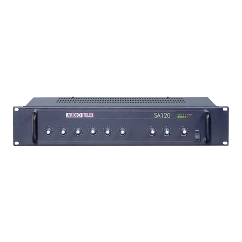
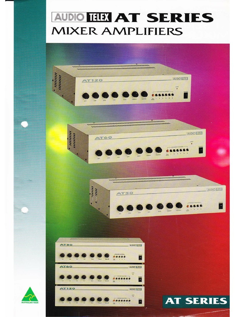
AT SERM,S MIXER AMPLIFIERS
Congrafulations on purchasing an AT Seris; Mixer Amplifier. As yort are no doubt arvare. MAINS POWER MUST BE
DISCONNECTED BEFORE REMOVING THE LID OR MAKING ANY INTERNAL ADJUSTMENT TO THE
AMPLIFIER
The AT Mixer Ailrplitiers are self standing with rubber feet. They may be stackerl to a maximun ol tour sxj1' high. An IEC type
nnins cord an4 receptacle is provided, the receptacle also houses the mains f-use in a drawer, which pulL oftrl trr e\pose the fuse.
SETTING UP
oooo o,o,
;.
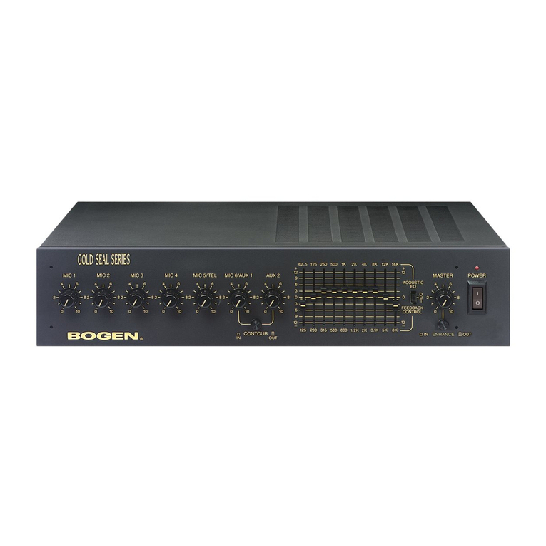
PANEL CONTROLS (fig l );
i _1 1 CUt-+ Marked one to four tlrese i:ontrols will respontl to either Microphone lnptrls or the Auxiliary InpuLs conne.cted at the
rcar of the amplifier( .ctc Connedion.; lalcr n the-se n.cmtc'tion'c ).
The setting will depend upon the sensitivify of the Microphone or Auxilian' progrim source. Generally a setting of seven will be
ideal for a standard dynamic microphone and five lbr most program inputs. However as conditions vary , adjust the setting to suit
the required perfbrmance levcl tbr your system.
i t BASS The Bass control will normally be operated in the mid position (5) to obtain a flat response from the amplifier' To
booit the bass response of the anrplifier , turn the conEol towards the higher number setting .To reduce bass response turn the
confiol toward the lowcr numberrd setting . For many paging only systems it is a good idea to operate the bass control in
a lower setting, to cut bass and improve intelligibility, however rhis may depreciate the amplifiers' performance for
music reproduction.
i - j I TREBLE The Trcble control will normally be operated in the mid position (5) , to obtain a flat response from the
o*ptiti". .To boost the high frequency respor$e of the amplifier , turn the control towards the high nrrmbered setting. To reduce
tSehigh fraluency response of the amplifier , nrn the control towards the lower mrmbff setting.
-11
position
required.
i - erl CALL The ORANGE "AU call " switch when pusherl on , will conncct the 100 volt output of the aniplifier to all
speakers or zones .Push the switch again to tum off this function.
| 6 SpEAKER SELECTOR The speaker selector consists of six BLACK speaker or zone selector switches designated one to
ii*-i rout in the case of the AT30 ) . press the switch "IN" to turn it on, this will connect the 100 volt output of the amplifier to
the speaker or 21)ne selected . push the switch again to turn off this function. Any conbination of switches may be activated
simultaneously , Each switch has a maximum capacity of 60 watts. Care should be taken to ensure the total power of the amplifier
is not exceed e(Connection for each of fue gnaker or zon6 ts' made at the rea.r of the amphlier , 'w "Connrctnns " later m
furc msauctrorc. )
7 18
MASTER This control adjusts the overall volurne from the output of the mixer section of the amplitier. The normal
for this control is 6, providing scope for the volume level to be adjusted up or down from the normal positron as
