Helmer i.Series iUF118 User manual

Ultra-Low Freezer Operation Manual
i.Series®
360172-A/D
i.Series
iUF118
iUF126
i.Series
iUF116
iUF124

Document Updates
The document is furnished for information use only, is subject to change without notice and should not be construed as a
commitment by Helmer Scientic. Helmer Scientic assumes no responsibility or liability for any errors or inaccuracies that may
appear in the informational content contained in this material. For the purpose of clarity, Helmer Scientic considers only the most
recent revision of this document to be valid.
Notices and Disclaimers
Condential / Proprietary Notices
Use of any portion(s) of this document to copy, translate, disassemble or decompile, or create or attempt to create by reverse
engineering or otherwise the information from Helmer Scientic products is expressly prohibited.
Copyright and Trademark
Copyright © 2017 Helmer, Inc. Helmer®, i.Series®, i.C³®, and Rel.i™ are registered trademarks or trademarks of Helmer, Inc. in the
United States of America. All other trademarks and registered trademarks are the property of their respective owners. Helmer, Inc.,
doing business as (DBA) Helmer Scientic and Helmer.
Disclaimer
This manual is intended as a guide to provide the operator with necessary instructions on the proper use and maintenance of
certain Helmer Scientic products.
Any failure to follow the instructions as described could result in impaired product function, injury to the operator or others, or void
applicable product warranties. Helmer Scientic accepts no responsibility for liability resulting from improper use or maintenance of
its products.
The screenshots and component images appearing in this guide are provided for illustrative purposes only, and may vary slightly
from the actual software screens and/or product components.
Helmer Scientic
14400 Bergen Boulevard
Noblesville, IN 46060 USA
www.helmerinc.com
ISO 13485:2003 CERTIFIED Part No. 360172-A Rev D
Document History
Revision Date CO Supersession Revision Description
A10 APR 2014* 9339 n/a Initial release.
B 12 DEC 2014 10128 B supersedes A Captured product changes prior to product launch
C 05 JAN 2015 11402 C supersedes B Added instructions for removal of compressor restraints. Updated initial charge values in
Specications table.
D17 FEB 2017 12611 D supersedes C Reformatted for documentation consistency and ease of use. Updated and added content
and screenshots to i.Series Operation as required by software platform changes.
* Date submitted for Change Order review. Actual release date may vary.

Helmer Scientic i.Series®Ultra-Low Freezer Operation Manual
360172-A/D ii
Contents
1 About this Manual................................................................................................ 3
1.1 Safety Precautions and Symbols ...............................................................................3
1.2 General Recommendations ...................................................................................4
2 Installation ...................................................................................................... 5
2.1 Location...................................................................................................5
2.2 Remove Compressor Restraints................................................................................5
2.3 Placement and Leveling ......................................................................................5
2.4 Rear Stand-Offs ............................................................................................ 6
2.5 AC Power Cord Retainer...................................................................................... 6
2.6 Storage Shelves ............................................................................................7
2.7 Chart Recorder (optional) .....................................................................................7
3 i.Series Operation ................................................................................................ 8
3.1 Initial Start Up ..............................................................................................8
3.2 Operation ................................................................................................. 9
3.3 Change Temperature Setpoint ................................................................................ 10
3.4 Set Alarm Parameters........................................................................................11
3.5 Active Alarms .............................................................................................12
3.6 Mute and Disable Active Alarms ...............................................................................12
4 Min/Max Temperature Monitoring .................................................................................. 13
5 Access Control ................................................................................................. 14
5.1 Setup....................................................................................................14
5.2 Open Freezer with Access Control ............................................................................. 15
6 ProductSpecications ........................................................................................... 16
6.1 Operating Standards........................................................................................16
7 Compliance .................................................................................................... 18
7.1 Regulatory Compliance...................................................................................... 18
7.2 Electromagnetic Compliance .................................................................................18
8 Preventive Maintenance .......................................................................................... 19
Appendix A......................................................................................................... 20
Application Icons................................................................................................. 20
Appendix B......................................................................................................... 21
Exterior Components.............................................................................................. 21
Interior Components .............................................................................................. 22
Helmer Scientic i.Series®Ultra-Low Freezer Operation Manual
360172-A/D 3
1 About this Manual
This manual provides information on how to use the i.Series® Ultra-Low freezer. It is intended for use by end users of the freezer and
authorized service technicians.
Models are indicated by a distinguishing model number that corresponds to the series, type, number of doors and capacity of the
freezer. For example, “iUF124” refers to an i.Series Ultra-Low Freezer with 1 door and a capacity of 24 cu ft. This manual covers all
ultra-low freezers, which may be identied singly, or by their size.
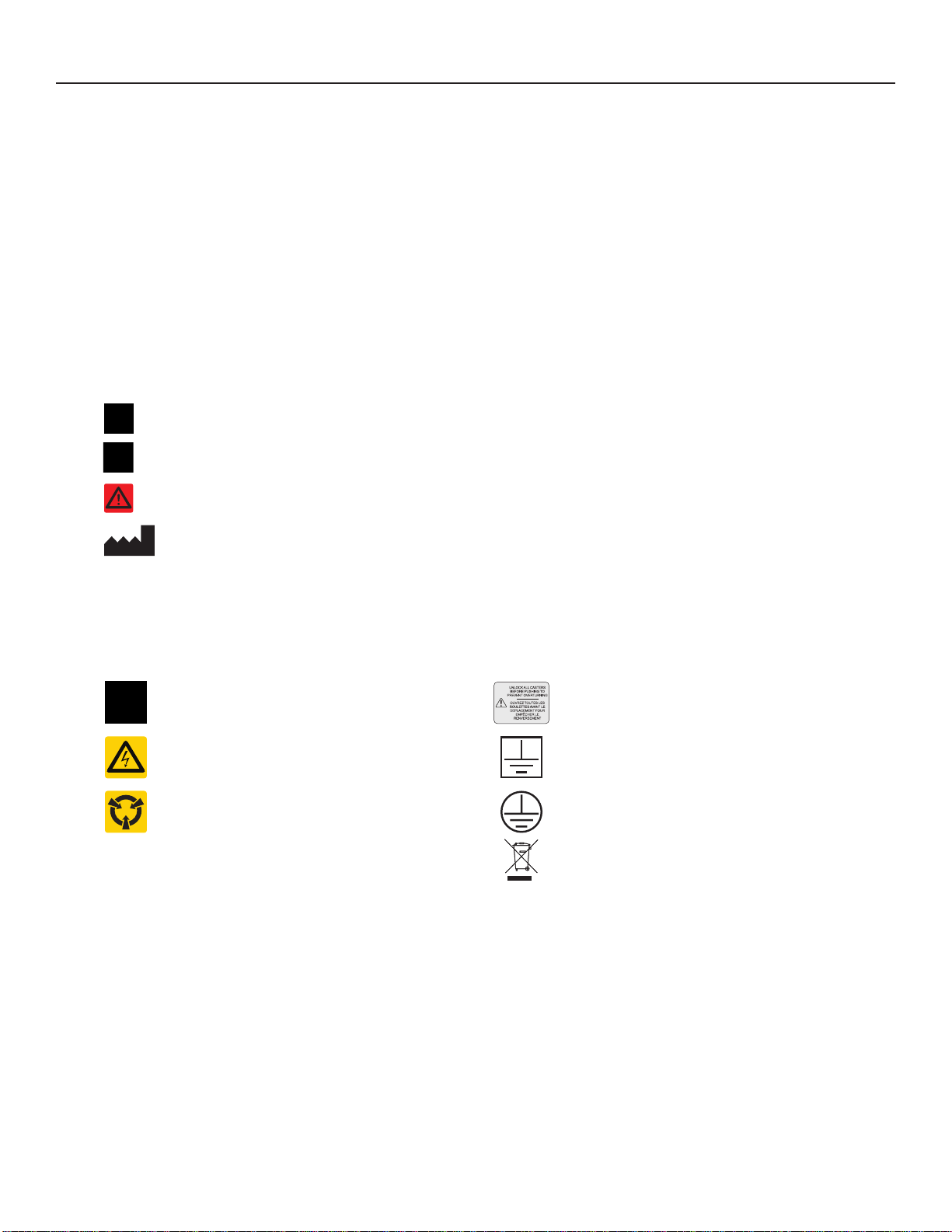
1.1 Safety Precautions and Symbols
Symbols found in this document
The following symbols are used in this manual to emphasize certain details for the user:
Task Indicates procedures which need to be followed.
Note Provides useful information regarding a procedure or operating technique when using Helmer
Scientic products.
NOTICE Advises the user against initiating an action or creating a situation which could result in damage to
equipment; person injury is unlikely.
CAUTION Advises the user against initiating an action or creating a situation which could result in damage
to equipment or impair the quality of the products or cause minor injury.
WARNING Advises the user against initiating an action or creating a situation which could result in damage
to equipment and serious personal injury to a patient or the user.
Manufacturer
Symbols found on the units
The following symbols may be found on the freezer or freezer packaging.
Caution: Safety hazard to operator or
service technician Caution: Unlock all casters
Caution: Electrocution/shock hazard Earth / ground terminal
Caution: Electrostatic discharge (ESD)
hazard Protective earth / ground terminal
Compliance with European Union Directive
WEEE 2002/96/EC applicable provisions.

Helmer Scientic i.Series®Ultra-Low Freezer Operation Manual
360172-A/D 4
Avoiding Injury
Review safety instructions before installing, using, or maintaining the equipment.
♦ Before moving unit, remove contents from the chamber.
♦ Before moving unit, ensure door is closed and latched, and casters are unlocked and free of debris.
♦ Before moving unit, disconnect the AC power cord and secure the cord.
♦ When moving unit, use assistance from a second person.
♦Never physically restrict any moving component.
♦Avoid removing electrical service panels and access panels unless so instructed.
♦ Use appropriate gloves when handling cold internal components and stored inventory.
♦ Keep hands away from pinch points when closing the door.
♦ Avoid sharp edges when working inside the electrical compartment and refrigeration compartment.
♦ Ensure biological materials are stored at recommended temperatures determined by standards, literature, or good
laboratory practices.
♦ Total freezer weight (including contents) is not to exceed 1400 lbs (635 kg).
♦ Use manufacturer supplied power cord only.
♦ Using the equipment in a manner not specied by Helmer may impair the protection provided by the equipment.
♦ Ensure biological materials are stored safely, in accordance with all applicable organizational, regulatory, and
legal requirements.
♦ The freezer is not considered to be a storage cabinet for ammable or hazardous materials.
CAUTION
Decontaminate parts prior to sending for service or repair. Contact Helmer or your distributor for decontamination instructions
and a Return Authorization Number.
1.2 General Recommendations
Intended Use
Helmer ultra-low freezers are intended to provide a controlled temperature environment at ultra-low temperatures required for the
storage of biological materials, pharmaceuticals, and reagents used in a research or clinical laboratory.
The devices referenced in this manual are intended to be operated by personnel who have procedures in place for meeting FDA,
AABB, or any other applicable regulations for the processing and storage of biological materials, pharmaceuticals, and reagents.
General Use
Allow freezer to come to room temperature before switching power on.
During initial startup, the high temperature alarm may sound while the freezer reaches operating temperature.
NOTE
This unit is not a “rapid-freezing” device. Freezing large quantities of liquid, or high-water content items, will temporarily
increase the chamber temperature and will cause the compressors to operate for a prolonged period of time.
Initial Loading
Allow chamber temperature to stabilize at the setpoint before storing pre-frozen product.
Product Loading Guidelines
When loading your freezer, take care to observe the following guidelines:
♦ Never load freezers beyond capacity.
♦ Always store items within shelves.

Helmer Scientic i.Series®Ultra-Low Freezer Operation Manual
360172-A/D 5
2 Installation
2.1 Location
♦ Has a dedicated 15 A grounded circuit with dedicated single point receptacle meeting the electrical requirements listed on the product
specication label.
♦ Is clear of direct sunlight, high temperature sources, and heating and air conditioning vents.
♦ Minimum 8” (203 mm) above, and minimum 4” (102 mm) behind.
♦ Meets limits specied for ambient temperature and relative humidity.
2.2 Remove Compressor Restraints
1. Using ½” socket and ½” open-end wrench, remove the hex bolt securing the compressor
restraint under the high-stage compressor. Set hex bolt, washer and hex nut aside for use
in installing rubber compressor foot (Qty.: 1 per compressor).
2. Lift compressor mounting plate slightly and slide restraint out.
3. Remove rubber compressor foot and metal spacer from accessories box.
4. Slide the compressor foot under the compressor mounting plate and align hole in the foot
with opening in the bottom of the freezer and mounting plate.
5. Insert metal spacer in the center of rubber compressor foot.
6. Insert hex bolt through bottom of freezer and up through compressor foot and
mounting plate.
7. Place washer and hex nut over the protruding hex bolt. Hand-thread hex nut.
8. Secure using torque wrench, and tighten to 78.8 in-lbs.
9. Repeat steps 1 – 8 for low-stage compressor.
Note
When removing the compressor restraint from the low-stage compressor, approach
from the left side of the compressor to avoid damage to the copper tubing mounted
to the oor of the refrigeration compartment.
10.Place rear panel over refrigeration compartment and align holes in panel with threaded
holes in freezer.
11.Hand thread screws and tighten using #2 Phillips screwdriver .
2.3 Placement and Leveling
CAUTION
• To prevent tipping, ensure door is closed and latched, and casters are unlocked and free of debris before moving freezer.
• The freezer is extremely heavy. Helmer recommends two people work together to move the freezer.
1. Ensure all casters are unlocked and door is closed and latched.
2. Roll freezer into place and lock casters.
3. Adjust leveling feet (if installed) to ensure freezer is level.
Compressor restraint
Rubber foot with spacer
Rubber foot installed
Rear panel

Helmer Scientic i.Series®Ultra-Low Freezer Operation Manual
360172-A/D 6
2.4 Rear Stand-Offs
CAUTION
The rear stand-offs include a hole to accept a threaded fastener for anchoring the freezer to a wall. The rear stand-offs do not
provide a secure means to anchor the freezer to the wall that can be considered resistant to seismic events.
Notes
• Installation of the rear stand-offs is optional.
• Anchoring the freezer to the wall is optional.
• Hardware to anchor the freezer to the wall is not provided with the freezer. The end user is responsible for determining the
best method to anchor the freezer to the wall.
Install Rear Stand-Offs
Rear Stand-off
1. Align the holes in the stand-offs with the corresponding threaded holes on the back of the freezer.
2. Insert the 3/8” hex head cap screws through the holes in the stand-offs.
3. Hand-thread the cap screws into the threaded holes.
4. Using a 9/16” open-ended wrench, tighten the cap screws.
2.5 AC Power Cord Retainer
NOTICES
• Do not position the freezer where it will prevent access to the power cord disconnect at the wall receptacle.
• Use only manufacturer supplied power cord.
Install Power Cord Retainer
1. Insert the power cord into the receptacle on rear of the cabinet.
2. Slide the retainer upward, engaging the groove in the power plug with the slot in the retainer.
3. Align the holes in the retainer with the corresponding holes on the cabinet.
4. Insert the screws with lock washers through the retainer and into the holes in the cabinet.
5. Using a #2 Phillips screwdriver, tighten the screws.
Power Cord Retainer

Helmer Scientic i.Series®Ultra-Low Freezer Operation Manual
360172-A/D 7
2.6 Storage Shelves
Note
Shelf clips must be installed so the horizontal section is oriented upward.
Install Shelves with Shelf Clips
1. Open the chamber door and all inner doors.
2. Install shelf clips on the shelf standards at the marked locations.
3. Beginning with the bottom shelf, insert the shelf into the chamber at an angle.
4. Rotate the shelf so it sits at on the shelf clips.
5. Working from the bottom to the top, install the remaining shelves as described
in steps 3 and 4.
6. Close the inner doors and the chamber door.
Shelf Clip Installed shelves
2.7 Chart Recorder (optional)
Chart Recorder with paper installed
Install / Replace Chart Paper
Note
For accurate temperature reading, ensure current time is aligned with time line groove when the chart knob is fully tightened.
Chart recorder stylus and time line groove
1. Press and hold C button. When stylus begins to move left, release button. The LED ashes.
2. When stylus stops moving, remove chart knob then move knob up and away.
3. Place chart paper on chart recorder.
4. Gently lift stylus and rotate paper so current time line corresponds to time line groove.
5. Hold chart paper in place while making sure the chart knob is fully tightened. (Failure to fully tighten the knob can result in paper
slipping and losing time.)
6. Press and hold C button. When stylus begins to move right, release button.
7. Conrm stylus is marking on paper and stops at the correct temperature.
8. Calibrate chart recorder to match primary temperature if needed and close recorder door.

Helmer Scientic i.Series®Ultra-Low Freezer Operation Manual
360172-A/D 8
3 i.Series Operation
3.1 Initial Start Up
1. Plug the power cord into a 15 A grounded circuit with a dedicated single point receptacle.
2. Switch battery ON/OFF switch ON.
3. Switch AC ON/OFF switch ON.
Note
The Start screen is displayed when the i.C3 is powered on. The i.C3 monitoring and control system will take approximately
three minutes to boot up.
Start screen
The language screen is displayed after the i.C3 is powered on. Use the Language screen to select the i.C3display language.
Language screens
Note
English is the default language.

Helmer Scientic i.Series®Ultra-Low Freezer Operation Manual
360172-A/D 9
If an alarm sounds, temporarily mute the alarm by touching the Mute icon.
Home screen - alarm muted Muted icon
Note
Active alarms are displayed on the Home screen. If an alarm condition other than High Temperature occurs, refer to the
service manual for troubleshooting.
3.2 Operation
Notes
• Refer to the i.C3 User Guide for Ultra-Low Freezers for complete information regarding the i.C3User Interface.
• The i.C³ Home screen displays temperature and alarm information, and provides icons to gain access to other functions of
the i.C³.
• After two minutes of inactivity, the screensaver will be displayed. To return to the Home screen, touch the screensaver.
Home screen Home screensaver

Helmer Scientic i.Series®Ultra-Low Freezer Operation Manual
360172-A/D 10
3.3 Change Temperature Setpoint
Note
The Temperature Setpoint toggle button can be accessed from either the initial Settings screen or the Device Control Settings
screen.
> > Enter the Settings password. Select Temperature Setpoints. Touch minus (-) or plus (+) on spin box to change value.
Settings screen Device Control Settings screen
Notes
• Default Settings password is 1234.
• Default setpoint is -80.0 °C.

Helmer Scientic i.Series®Ultra-Low Freezer Operation Manual
360172-A/D 11
3.4 Set Alarm Parameters
> > Enter the Settings password. Scroll down to select Alarm Settings. Touch minus (-) or plus (+) on spin box to set
each alarm parameter.
Settings screen
Alarm Settings screens
Alarm settings control the circumstances and timing of alarm condition indicators displayed on the i.C³ Home screen.

Helmer Scientic i.Series®Ultra-Low Freezer Operation Manual
360172-A/D 12
3.5 Active Alarms
Home screen with active alarm
Table 1. i.Series Active Alarms
Alarm Description
Primary Monitor Probe High Temp Primary monitor probe reading is above high temperature alarm setpoint
Primary Monitor Probe Low Temp Primary monitor probe temperature reading is below low temperature alarm setpoint
Probe Failure Probe not functioning properly
Ambient Probe High Temp Ambient temperature reading is above high temperature alarm setpoint
Ambient Probe Low Temp Ambient temperature reading is below low temperature alarm setpoint
Clean Filter Evaporator defrost probe not functioning properly
CO2/ LN2Active CO2/ LN2 back-up refrigeration system is active
Refrigeration System
Refrigerant pressure is too high
High stage compressor temperature is too high
Low stage compressor temperature is too high
High stage compressor has failed
Low stage compressor has failed
Power Failure Power to unit has been disrupted
Door Open Door is open beyond user-specied duration
Low Battery Rechargeable battery voltage is low
No Battery Battery is not connected
Communication Failure Messages
1, 2, 3
1 Communication lost between i.C³ display board and control board
2 Communication lost between i.C³ display board and internal system memory
3 Corrupt database
Emergency Mode Control probe temperature sensor failed or is failing intermittently and refrigeration
system is operating at 100% duty cycle (alarm is only displayed on Home Screen)
3.6 Mute and Disable Active Alarms
Audible alarms may be muted by touching the Mute icon to set delay. Touching the Mute icon repeatedly will increase the Mute
timer incrementally.

Helmer Scientic i.Series®Ultra-Low Freezer Operation Manual
360172-A/D 13
4 Min/Max Temperature Monitoring
The Min/Max temperature display provides the highest and lowest Primary Monitor probe temperature reading since the last system
reset (power-on event) or manually-initiated reset. Touch the Reset icon to the right of the display to manually reset.
Notes
• The Min/Max temperature display can be turned on or off through Display Settings.
• Once the time reaches the maximum display of 999 hours and 60 minutes, the message will display “>999:60”, but
minimum and maximum temperatures will continue to be tracked.

Helmer Scientic i.Series®Ultra-Low Freezer Operation Manual
360172-A/D 14
5 Access Control
Allows user-specic secure access to the freezer.
Notes
• The Supervisor PIN must be used to set up user proles.
• The Supervisor PIN does not allow access to the unit. At least one user ID must be set up to gain access to the unit.
• The Supervisor PIN should be changed to prevent unauthorized user ID setup. The Supervisor PIN can not be deleted.
• In the event the Supervisor PIN is unavailable, contact Helmer Technical Service to reset the Supervisor PIN.
• When setting up Access Control user IDs, ensure the key lock is in the locked position to prevent unauthorized access to
the freezer.
• The keys provided with the freezer may be used to lock or unlock the exterior door.
• Refer to the i.C3 User Guide for i.Series Ultra-Low Freezers for complete information regarding Access Control.
5.1 Setup
Congure and manage multiple user-specic accounts to allow controlled access to the freezer.
> > Access Setup
Access Control Setup screen with password keypad overlay Access Control Setup screen
Note
The Access Setup button can be found on the Users and Passwords screen or the Access Log screen.
Entry into Access Control Setup
1. Touch the Access Setup button. A numeric keypad is displayed.
2. Enter the supervisor PIN (if entering for the rst time, use the factory supervisor PIN = 5625).
3. Touch to conrm. The keypad closes and the Access Control Setup screen is displayed.
Addauserprole
1. Touch the Add User button. An alphanumeric keyboard is displayed.
2. Enter the User ID for the new user prole.
3. Touch the to store the user ID. The numeric keyboard is displayed.
4. Enter a 4-digit PIN for the new user prole.
5. Touch the to store the user PIN. The User ID and PIN for the new user prole are displayed in the table.

Helmer Scientic i.Series®Ultra-Low Freezer Operation Manual
360172-A/D 15
5.2 Open Freezer with Access Control
Access Control Keypad
Using Access Control to unlock the door
1. Enter unique 4-digit PIN.
2. If a valid PIN is entered, the Padlock indicator appears open and the door is unlocked.
Helmer Scientic i.Series®Ultra-Low Freezer Operation Manual
360172-A/D 16
6 ProductSpecications
6.1 Operating Standards
♦Indoor use only
♦ Altitude (maximum): 2000 m
♦ Ambient temperature range: 15 °C to 32 °C
♦ Relative humidity (maximum for ambient temperature): 80% for temperatures up to 25 °C, decreasing linearly to 53% at 32 °C
♦ Temperature control range: -50 °C to -86 °C
Note
Power conditioning (voltage boost) is an optional feature. If facility voltage is consistently at or below 195 V, voltage boost must
be installed in order to protect the compressors.
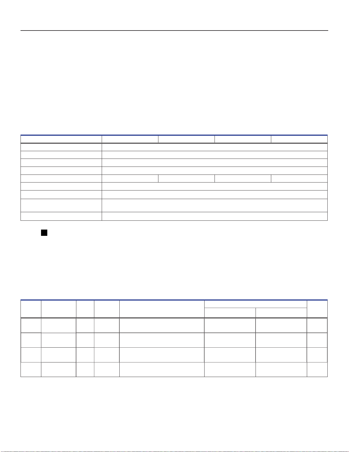
Table2.ElectricalSpecications
Model 116 118 124 126
Input Voltage and Frequency 208/230 V, 60 Hz
Voltage Tolerance ±10%
Circuit Breakers 12.0 A (quantity 2)
Current Draw 11.0 A
Energy Consumption 18.5 kWh/day 18.5 kWh/day 19 kWh/day 19 kWh/day
Power Source 15 A dedicated circuit
Boost Cut-in Voltage 195 V
Monitoring System Battery /
Chart Recorder Battery 12 V, 7 Ah rechargeable sealed lead acid battery
Remote Alarm Capacity 0.5 A at 30 V (RMS); 1.0 A at 60 V (DC)
CAUTION
• The interface on the remote alarm monitoring system is intended for connection to the end user’s central alarm system(s)
that uses normally-open or normally-closed dry contacts.
• If an external power supply exceeding 30 V (RMS) or 60 V (DC) is connected to the remote alarm monitoring system’s
circuit, the remote alarm will not function properly; may be damaged; or may result in injury to the user.
Note
Overall exterior dimensions include casters, handle, i.C3 bezel, and door hinges
Table3.Ultra-LowFreezerSpecications
Model Voltage Code Amps
Capacity
Cu. Ft
(Liters) Dimensions Interior
W x H x D in. (mm)
Dimensions W x H x D in. (mm) Net Wt.
lbs (kg)Exterior Overall Exterior
iUF116 208/230 V
60 Hz 11.0 16
(453) 23.1 x 49.5 x 23.3
(587 x 1257 x 592) 33.8 x 78.2 x 34.8
(859 x 1986 x 884) 37.1 x 78.2 x 37.5
(942 x 1986 x 953) 607
(275)
iUF118 208/230 V
60 Hz 11.0 18
(510) 23.1 x 54.1 x 23.3
(587 x 1374 x 592) 28.9 x 78.2 x 34.8
(734 x 1986 x 884) 32.5 x 78.2 x 37.5
(826 x 1986 x 953) 622
(282)
iUF124 208/230 V
60 Hz 11.0 24
(680) 34.4 x 49.5 x 23.3
(874 x 1257 x 592) 45.1 x 78.2 x 34.8
(1146 x 1986 x 884) 48.4 x 78.2 x 37.5
(1229 x 1986 x 953) 704
(319)
iUF126 208/230 V
60 Hz 11.0 26
(736) 34.4 x 54.1 x 23.3
(874 x 1374 x 592) 40.2 x 78.2 x 34.8
(1021 x 1986 x 884) 43.8 x 78.2 x 37.5
(1113 x 1986 x 953) 725
(328)
Helmer Scientic i.Series®Ultra-Low Freezer Operation Manual
360172-A/D 17
Note
Vacuum-insulated panels are included in cabinet walls on indicated models. All models feature vacuum-insulated panels in the
exterior door.
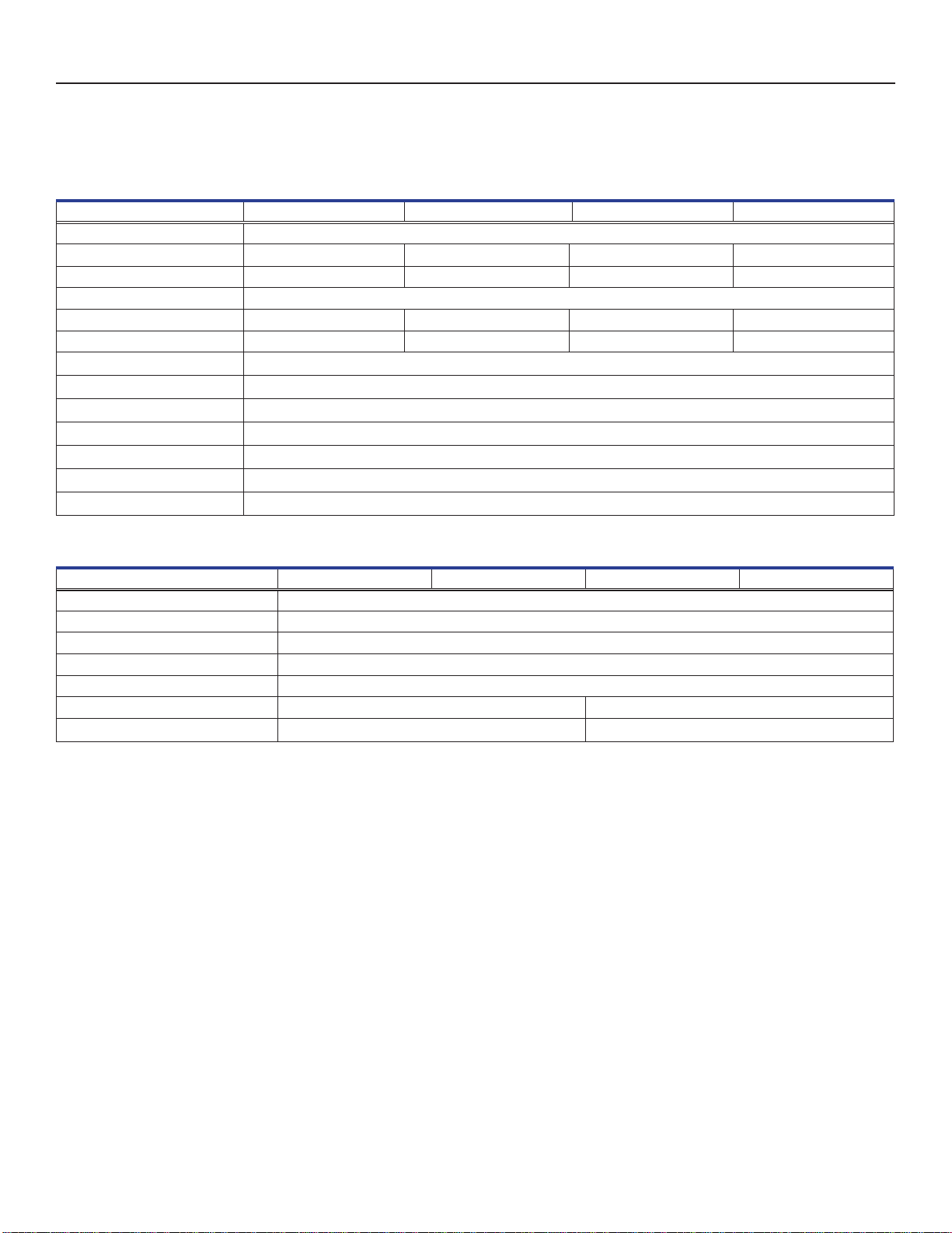
Table4.Interior/ExteriorCabinetSpecications
Model 116 118 124 126
Insulation Ecomate® insulating foam (non-ODP, non-GWP, and VOC-exempt blowing agent foam)
Vacuum-Insulated Panels --
Wall Thickness 5.0” (127 mm) 2.7” (69 mm) 5.0” (127 mm) 2.7” (69 mm)
Door Thickness 2.7” (69 mm)
Internal Compartments 4 5 4 5
Shelves 3 Stainless steel 4 Stainless steel 3 Stainless steel 4 Stainless steel
Maximum Shelf Load 160 lbs (73 kg)
Internal Material Galvannealed steel with bacteria-resistant powder-coated nish
External Material Galvannealed steel with bacteria-resistant powder-coated nish
External Port 2, standard (top-left corner, rear of cabinet; bottom-left corner, rear of cabinet)
Vacuum Break Port Standard (heated)
Temperature Chart Recorder Optional, 4” (102 mm), 7-day inkless, pressure-sensitive chart paper, backup battery; ±0.5 °C (0.9 °F) accuracy
i.C3Monitor ±0.5 °C (0.9 °F) at setpoint accuracy
Table5.RefrigerationSystemSpecications
Model 116 118 124 126
High Stage Refrigerant R-404A, CFC/HCFC-free
Low Stage Refrigerant R-508B, CFC/HCFC-free and R601 natural refrigerant
High Stage Compressor 1.5 HP, air-cooled
Low Stage Compressor 1.5 HP, air-cooled
High Stage Initial Charge 29 oz. (822 g)
Low Stage Initial Charge (R508B) 13.5 oz. (383 g) 15.3 oz. (434 g)
Low Stage Initial Charge (R601) 0.77 oz. (22 g) 0.89 oz. (25 g)

Helmer Scientic i.Series®Ultra-Low Freezer Operation Manual
360172-A/D 18
7 Compliance
7.1 Regulatory Compliance
This product is certied to applicable UL and CSA standards by a NRTL
Sound level is less than 70 dB(A).
7.2 Electromagnetic Compliance
This device is suitable for use in a specic electromagnetic environment. The end user of this device is responsible for ensuring the
device is used in compliance with the following European Union directives and standards regarding EMC (electromagnetic compliance):
EMC Directive (2004/108/EC) Standards:
♦ EN 55011:2009
♦ EN 61000-3-2:2006
♦ EN 61000-3-3:2008
♦ EN 61000-6-1:2007

Helmer Scientic i.Series®Ultra-Low Freezer Operation Manual
360172-A/D 19
8 Preventive Maintenance
Notes
• It is important to ensure that all scientic equipment is maintained regularly for optimum performance.
• These are recommended minimum requirements. Regulations for your organization or physical conditions at your facility
may require maintenance items to be performed more frequently, or only be designated service personnel.
Maintenance tasks should be completed according to the following schedule. Refer to the service manual and the i.C³ User Guide for
detailed information on tasks.
Table 6. Preventive Maintenance Schedule
Task Frequency
Quarterly Annually 2 years As Needed
Verify the monitor/chamber temperature sensor accuracy. Calibrate the sensor
if necessary.
Verify the ambient temperature sensor accuracy. Calibrate the sensor if
necessary.
Test the High and Low chamber and Ambient Temperature alarms.
Test the Power Failure alarm (as required by your organization’s protocols).
Test the Door Open alarm.
Inspect electrical components and wiring terminals in the electrical box for
discoloration. Contact Helmer Technical Service if any discoloration is found.
Inspect and clean the condenser lter.
Replace the i.C3 backup battery
Defrost and clean the chamber, exterior door gasket, and inner doors.
NOTICE
• Inspect and clean the condenser lter as directed in the maintenance schedule, or when prompted by the i.C³ control and
monitoring system.
• The Clean Filter alarm monitors the condition of the air lter as a safety measure. The alarm is designed to warn if the lter
media becomes clogged such that freezer operation and product integrity will be affected.
• The Clean Filter alarm could indicate a failure of the condenser fan.
Notes
• During a power failure, the backup battery provides power to the monitoring system, power failure alarm, and chart recorder
(if equipped). If the backup battery is not functioning, the power failure alarm will not be activated.
• If the backup battery does not provide power to the monitoring system during the power failure alarm test, replace
the battery.
• During a power failure, the Access Control lock will continue to secure the door. To access the freezer during a power
failure, the override key must be used.
This manual suits for next models
3
Table of contents
Other Helmer Freezer manuals


