Helmer i.series User manual

Undercounter Freezer
Service Manual
i.Series™ and Horizon Series™
Plasma Models
• i.Series: iPF105 (Version B)
• Horizon Series: HPF105 (Version B)
Laboratory Models
• i.Series: iLF105 (Version B)
• Horizon Series: HLF105 (Version B)
Model
S/N
0086
ISO 13485:2003 CERTIFIED
HELMER, INC.
14395 Bergen Boulevard
Noblesville, IN 46060 USA
Phone +1 (317) 773-9073
USA and Canada (800) 743-5637
360142-1/E


i
360142-1/E
Section I: General Information......................................1
1 About this Manual ........................................................3
2 Safety ..................................................................4
2.1 Labels ..........................................................................4
2.2 Avoiding injury ....................................................................4
3 Conguration ............................................................5
3.1 Finding model and input power information..............................................5
3.2 Identifying the control system ........................................................5
3.3 Preparing the temperature probe......................................................6
3.4 Preparing the chart recorder .........................................................7
Section II: i.Series™ Models. . . . . . . . . . . . . . . . . . . . . . . . . . . . . . . . . . . . . . . .9
4 ProductConguration....................................................11
4.1 Installing batteries for backup power ..................................................11
4.2 Freezersetpointconguration .......................................................12
4.3 Automaticdefrostcycleconguration .................................................13
4.4 External monitoring devices.........................................................14
4.5 Moving drawers, shelves, and baskets ................................................15
4.6 Leveling the freezer ...............................................................16
4.7 Door characteristics ...............................................................17
4.8 Optional adapter kits for medication dispensing locks.....................................17
4.9 Door hinge and handle reversal, all models.............................................17
4.10 Hinge reversal (glass door and solid door) .............................................22
4.11 Hinge spring assembly reversal......................................................24
4.11 Stacking undercounter units ........................................................24
5 Temperature Controller Programs ..........................................25
5.1 Temperature setpoint settings .......................................................26
5.2 Temperature calibration settings .....................................................27
6 Maintenance ............................................................29
6.1 Recharging refrigerant.............................................................29
6.2 Checking the monitoring system backup battery.........................................30
6.3 Cleaning the freezer...............................................................30
6.4 Defrosting the freezer .............................................................31
6.5 Removing and installing the unit cooler cover ...........................................32
6.6 Removing and replacing the Access Control cartridge ....................................34
6.7 Supplies........................................................................36
7 Troubleshooting.........................................................37
7.1 General operation problems ........................................................37
7.2 Chamber temperature problems .....................................................38
7.3 Alarm activation problems ..........................................................39
7.4 Testing problems .................................................................42
7.5 Condensation and icing problems ....................................................43
Contents
Contents

ii
360142-1/E
8 Parts ..................................................................44
8.1 Control and monitoring.............................................................44
8.2 Front...........................................................................46
8.3 Rear and under ..................................................................47
8.4 Side access panel ................................................................50
8.5 Interior .........................................................................50
8.6 Door and hinge parts ..............................................................53
9 Schematics.............................................................54
9.1 iPFandiLFmodels;105conguration ................................................54
10 Settings................................................................56
10.1 Navigating the Home screen ........................................................56
10.2 Viewing and changing settings.......................................................57
10.3 Testing alarms ...................................................................60
10.4 Upgradingthesystemrmware ......................................................63
10.5 Calibrating the touchscreen.........................................................63
10.6 Viewing manufacturer and product information ..........................................63
11 Warranty ...............................................................64
11.1 Rel.i™ Product Warranty USA and Canada.............................................64
11.2 Outside of USA and Canada ........................................................65
12 References and Compliance...............................................66
12.1 Alarm reference ..................................................................66
12.2 Energy conservation and regulatory compliance.........................................66
Section III: Horizon Series™ Models................................67
13ProductConguration....................................................69
13.1 Installing batteries for backup power ..................................................69
13.2 Freezersetpointconguration .......................................................70
13.3 Automaticdefrostcycleconguration .................................................71
13.4 External monitoring devices.........................................................74
13.5 Moving drawers, shelves, and baskets ................................................75
13.6 Leveling the freezer ...............................................................76
13.7 Door characteristics ...............................................................77
13.8 Optional adapter kits for medication dispensing locks.....................................77
13.9 Door hinge and handle reversal, all models.............................................77
13.10 Hinge reversal (solid door with Access Control option) ....................................82
13.11 Hinge reversal (solid door without Access Control option)..................................84
13.12 Hinge spring assembly reversal......................................................86
4.11 Stacking undercounter units ........................................................86
14 Temperature Controller Programs ..........................................87
14.1 Hysteresis ......................................................................87
14.2 High alarm setpoint ...............................................................87
14.3 Low alarm setpoint................................................................87
14.4 Controltemperatureosetvalue .....................................................87
14.5 Monitortemperatureosetvalue .....................................................87
Undercounter Freezer Service Manual

iii
360142-1/E
15 Maintenance ............................................................88
15.1 Recharging refrigerant.............................................................88
15.2 Checking the monitoring system backup battery.........................................89
15.3 Cleaning the freezer...............................................................89
15.4 Defrosting the freezer .............................................................90
15.5 Removing and installing the unit cooler cover ...........................................91
15.6 Removing and replacing the Access Control cartridge ....................................93
15.7 Supplies........................................................................95
16 Troubleshooting.........................................................96
16.1 General operation problems ........................................................96
16.2 Chamber temperature problems .....................................................97
16.3 Alarm activation problems ..........................................................98
16.4 Condensation and icing problems ...................................................101
17 Parts .................................................................102
17.1 Control and monitoring............................................................102
17.2 Front..........................................................................103
17.3 Rear and under .................................................................104
17.4 Side access panel ...............................................................107
17.5 Interior ........................................................................107
17.6 Door and hinge parts .............................................................110
18 Schematics............................................................111
18.1 HPFandHLFmodels;105conguration..............................................111
19 Settings...............................................................112
19.1 Touring the monitoring and control system ............................................112
19.2 Viewing current settings...........................................................113
19.3 Changing settings ...............................................................114
19.4 Testing alarms ..................................................................115
20 Warranty ..............................................................117
20.1 Rel.i™ Product Warranty USA and Canada............................................117
20.2 Outside of USA and Canada .......................................................118
21 References and Compliance..............................................119
21.1 Alarm reference .................................................................119
21.2 Energy conservation and regulatory compliance........................................119
Contents

iv
360142-1/E
Undercounter Freezer Service Manual
This page left blank intentionally.

1
360142-1/E
Section I: General Information
Section I: General Information

2
360142-1/E
Undercounter Freezer Service Manual
This page left blank intentionally.

3
360142-1/E
General Information: About this Manual
1 About this Manual
This chapter explains the symbols and conventions used in this manual, copyright information about this
document, and trademark information for products supplied by Helmer.
1.1 Intended audience
This manual is intended for use by authorized end users and qualied service technicians, and is to be used
in conjunction with the i.C³™User Guide, Freezer Operation Manual, Chart Recorder Operation Manual,
and the Horizon Access Control Keypad User Guide, available on the CD shipped with the freezer.
1.2 Symbols and conventions
1.2.1 Cautions
A Caution is used to call attention to a condition or possible situation that could damage or destroy the
equipment or the operator’s work.
!
CAUTION Temperature probes are fragile. Handle them with care.
1.2.2 Notes
Notes contain additional information about a topic. Notes are used to provide information about how a
topic relates to another topic, or background information about a design characteristic.
NOTE Spare parts are available for purchase through Helmer.
1.2.3 Model references
Generic references are used to group undercounter freezers that contain similar features. For example,
“i.Series” refers to iPF105 and iLF105 freezers, and “Horizon Series” refers to HPF105 and HLF105
freezers. This manual covers all undercounter freezers, which may be identied singly or by their respective
“Series.”
Model Group i.Series Horizon Series
Plasma iPF105 HPF105
Laboratory iLF105 HLF105
1.3 Copyright and trademark information
Helmer®, i.Series®, i.C³™, Horizon Series™, and Rel.i™ are registered trademarks or trademarks of
Helmer, Inc. in the United States of America. Copyright © 2012 Helmer, Inc. All other trademarks and
registered trademarks are the property of their respective owners.

4
360142-1/E
Undercounter Freezer Service Manual
2 Safety
This chapter describes general safety information for servicing the freezer. The Freezer Operation Manual
includes additional safety information for operating the freezer. Your organization may provide additional
safety information.
2.1 Labels
Caution, risk of danger Caution, shock hazard
Caution, unlock all casters Earth ground terminal Protective earth ground terminal
2.2 Avoiding injury
► Review safety instructions before installing, using, or maintaining the equipment.
► Before performing procedures, review any specic safety instructions.
► Do not open multiple, loaded drawers at the same time.
► Before moving unit, ensure casters are free of debris.
► Avoid removing electrical service panels and access panels unless so instructed.
► Use supplied power cords only.
► Notify appropriate safety personnel when handling or disposing of materials that are infectious, toxic,
pathological, radioactive, or otherwise biologically or environmentally harmful.
!
CAUTION Decontaminate parts prior to sending for service or repair. Items not
decontaminated appropriately will not be accepted. Documentation stating
contents are not contaminated and are safe to handle must accompany returns.
Contact Helmer or your distributor for decontamination instructions and a
Return Authorization Number.
5
360142-1/E
3 Conguration
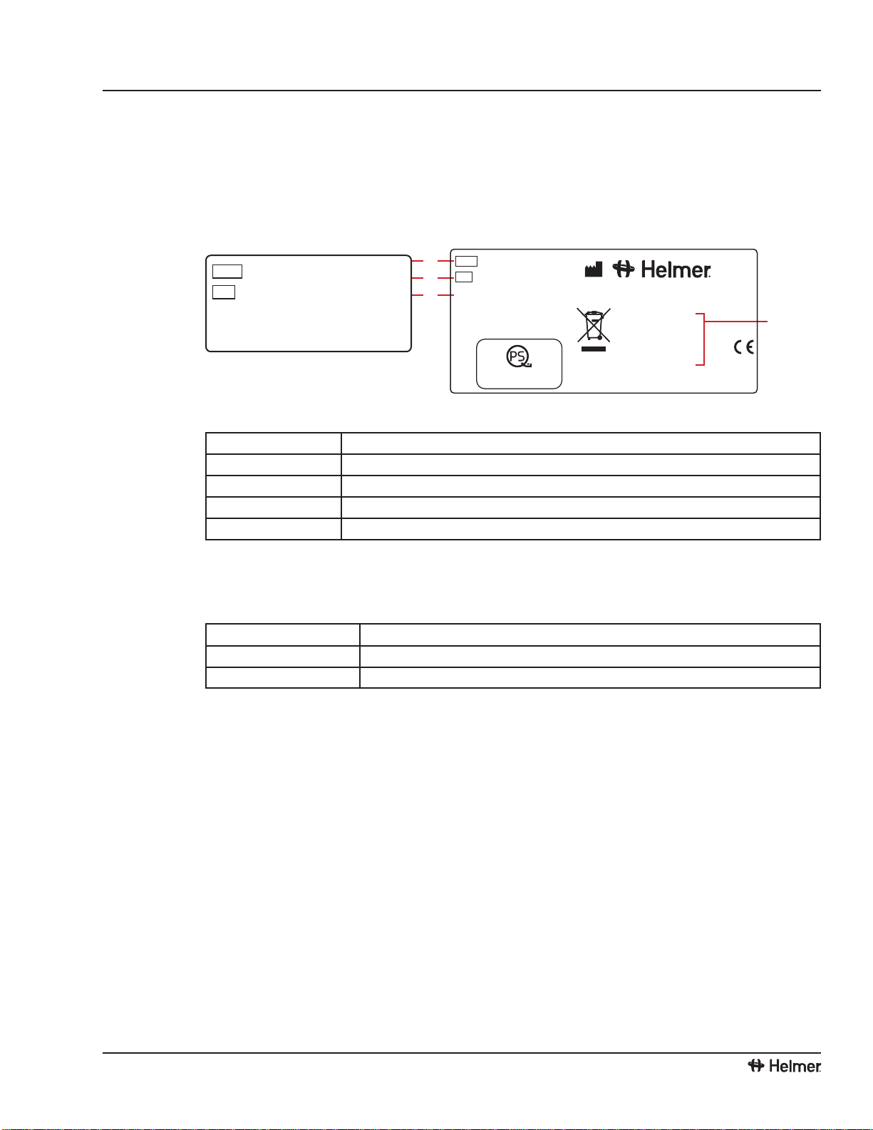
3.1 Finding model and input power information
Service information varies depending on the model and input power requirements. This information
appears on the Product Specication label, located on the rear of the freezer. The model also appears on a
label located in the chamber on the upper side of the right wall.
D
A
B
C
REF
SN ILF105
000000
Voltage 115 V
HZ 60
Amps 5.75 A
Version A
Laboratory Freezer
Weight 197 lb / 89 kg
www.helmerinc.com
Noblesville, IN USA
2011
0086
UL 61010-1/CSA 61010-1
Certified
CUS
REF
SN ILF105
000000
Version A
www.helmerinc.com
Left:Chamberlabel.Right:ProductSpecicationlabel(locatedontherearatlowerleft).
Label Description
A Model (REF)
B Serial number (SN)
C Version
D Power requirements
3.2 Identifying the control system
Service information varies depending on the control system. Helmer freezers have one of two control
systems installed. The type of control system varies by model.
Model group Control system
iB105 and iLR105 i.C³ monitoring and control system
HB105 and HLR105 Horizon Series monitoring and control system
3.2.1 i.C³ control system
i.Series freezers are equipped with the i.C³ monitoring and control system. The i.C³ system combines
temperature control and monitoring into a single interface, displaying multiple information logs with
historical information in full color. The touchscreen monitor, located on the freezer door, displays
operational information. The chamber temperature controller is integrated into the i.C³ system.
i.C³ monitoring and control system display.
GeneralInformation:Conguration

6
360142-1/E
3.2.2 Horizon Series control system
Horizon. Horizon Series freezers feature the Horizon combined monitor and temperature controller. The
Horizon Series system controls chamber temperature and monitors and displays operational information.
The user interface for this system is located on the freezer door.
Horizon Series monitoring and control system display.
3.3 Preparing the temperature probe
The temperature probe monitors chamber temperature.
In addition to using standard probes installed by Helmer, external probes may be introduced through the
existing rear port and immersed in the existing probe bottle.
For each probe bottle, obtain:
► Approximately 4 oz (120 ml) of product simulation solution. Solution is a 1:1 ratio of water to
propylene glycol (or equivalent low-temperature uid).
Left: Probe bottle with temperature probe. Right: Access port on rear of freezer.
To install an additional external probe through the rear
1 Peel back the putty to expose the port and insert probe through the port into chamber.
2 Insert probe into the bottle.
3 Replace putty, ensuring a tight seal.
Tollatemperatureprobebottle
!
CAUTION ► Clean bottle rst, as required.
► Temperature probes are fragile; handle with care.
1 Remove all probes from bottle.
2 Remove bottle from bracket and ll with approximately 4 oz (120 ml) of product simulation solution.
3 Cap tightly to minimize evaporation.
4 Place bottle in bracket and replace probes, immersing at least 2 inches (50 mm) in solution.
Undercounter Freezer Service Manual

7
360142-1/E
3.4 Preparing the chart recorder
If installed, see the Temperature Chart Recorder Operation and Service Manual on CD.
Complete these tasks to prepare recorder for use:
► Installing the backup battery.
► Adding paper.
► Calibrating the chart recorder to match the chamber temperature.
3.4.1 Accessing the chart recorder
► Pull the door open.
Opening the chart recorder door.
3.4.2 Changing chart paper
One piece of chart paper records temperatures continuously for seven days. For additional information on
changing the chart paper, see the Temperature Chart Recorder Operation and Service Manual on CD.
GeneralInformation:Conguration

8
360142-1/E
This page left blank intentionally.
Undercounter Freezer Service Manual

9
360142-1/E
Section II: i.Series™ Models
Section II: i.Series™ Models

10
360142-1/E
Undercounter Freezer Service Manual
This page left blank intentionally.
11
360142-1/E
i.Series™Models:ProductConguration
4 ProductConguration
4.1 Installing batteries for backup power
The monitoring systems and chart recorder each have a battery backup system, enabling a period of
continuous operation if power is lost.
NOTE The monitoring systems will start on battery power alone. If the freezer was
previously not connected to AC power and the backup battery is connected or
switched on, the monitoring system will begin running on battery power.
Battery life varies by manufacturer as well as voltage level remaining. Providing full power is available,
and no battery-related alarms are active, backup power is available for up to 20 hours (the Low Battery
alarm will activate after approximately 18 hours of battery use).
NOTE If AC power is lost, the monitoring system will automatically disable some
features to prolong backup battery power. Data collection functions will
continue until backup battery power is depleted.
!
CAUTION ► Before installing or replacing batteries, disconnect power to the freezer.
► When installing a replacement battery for the monitoring system, use only a
battery which meets the specications outlined in chapter 6.7 (Supplies).
The the battery is located below the chamber, behind the front cover. A cover plate must be removed to
access the backup battery.
Monitoring system backup battery (access panel removed).
Models Monitoring system Battery requirements
iPF105 and iLF105 Combined alarm monitoring and
control system One rechargeable 12 V lead acid
sealed battery
The rechargeable backup battery that is switched o for shipping. Switch the battery ON to provide the
monitoring system with backup power in the event of a main power failure.

12
360142-1/E
Undercounter Freezer Service Manual
4.2 Freezersetpointconguration
The temperature controller adjusts chamber temperature around the freezer setpoint. The controller
activates the compressor when the chamber probe registers temperature above the setpoint.
The controller also senses unit cooler temperature through a probe in the cooler. The temperature in the unit
cooler typically varies from the temperature in the chamber, so an oset value is used in the control system.
The unit cooler temperature combined with the oset value establishes the freezer setpoint.
NOTE The probe in the bottle is connected to the monitoring system and senses
chamber temperature. This probe does not impact the freezer setpoint.
4.2.1 Determining current freezer setpoint
First, conrm:
► Freezer has run for at least 24 hours to stabilize chamber temperature.
► Chamber temperature is not uctuating because of excessive door openings and closings.
► Freezer has been placed per location requirements. See operation manual.
► Preventive maintenance has been completed. See operation manual.
► Troubleshooting items associated with chamber temperature have been reviewed.
Obtain:
► An independent thermometer, calibrated and traceable per national standards.
► Tape. This is used to secure the probe to the thermometer.
1 Remove all probes from the probe bottle.
2 Unscrew the cap from the bottle.
3 Tape the independent thermometer to the temperature probe, and replace them in the bottle so their
ends are immersed at least 2 inches (50 mm).
4 On the independent thermometer, monitor temperature for about 10 minutes to determine an
approximate range.
5 From the range, calculate an approximate average temperature. This is the current setpoint.
6 Remove thermometer and probe from the bottle and remove tape.
7 Replace bottle cap, ensuring a tight t.
8 Place probes in bottle, immersing at least 2 inches (50 mm).

13
360142-1/E
i.Series™Models:ProductConguration
4.2.2 Changing freezer setpoint
The default setpoint is either -20.0 °C or -30.0 °C, depending on use.
Change the setpoint if:
► Your organization requires a chamber temperature dierent from the default setting.
► The normal chamber temperature is too high or low, even after completing preventive maintenance and
applicable troubleshooting tasks.
Before changing setpoint, conrm:
► Freezer has been placed per location requirements. See operation manual.
► Preventive maintenance has been completed. See operation manual.
► Troubleshooting items associated with chamber temperature have been reviewed.
The temperature controller is integrated into the monitoring and control system. The temperature
setpoint is congured through the i.C³ screen.
!
CAUTION Do not change setpoint to a value outside the temperature control range.
1 Determine the new setpoint temperature.
2 Determine the change in value to reach the desired setpoint. The adjustment should be about half
the dierence between the current setpoint and the new setpoint. For example, if the desired normal
temperature is -30.0 °C, but the current setpoint is -29.0 °C, then the dierence is 1.0 °C, and the
setpoint adjustment value would be 0.5 °C.
3 On the i.C³ screen, touch i.C³ APPS, i.C³ Settings. Enter the Settings password then touch
Temperature Setpoints.
NOTE The Settings screen may be password protected. A valid four-digit password
must be entered to view settings. If viewing settings for the rst time, enter the
factory default password of “1234”.
4 Touch plus (+) or minus (-) on the Temperature Setpoint spin box until the correct value appears. The
button increments are ±0.1 °C.
5 The setpoint is changed. Touch Home to return to the home screen.
4.3 Automaticdefrostcycleconguration
The freezer features an automatic defrost system. This system periodically runs to melt accumulated ice on
the evaporator, which can obstruct air ow and degrade the freezer’s capability to reach the temperature
setpoint.
The number of programmed defrost events is dependent on environmental conditions and the frequency
of usage. The recommended number of daily defrost cycles is three to four, programmed at even intervals.
Defrost events should take place when the freezer door is opened infrequently. Opening the door can raise
the chamber temperature above the normal defrost cycle temperature, typically 4 °C to 10 °C above the
freezer setpoint.
NOTE Depending on the high temperature alarm setpoint and the actual temperature
increase during the defrost cycle, frequent door openings may trigger repeated
high temperature alarms.
The defrost settings are integrated into the temperature monitoring and control system. The i.C³ can
perform a maximum of four defrost cycles per day. Specify the number of defrost cycles per day and
the time at which each of the defrost cycles is to occur. The timing for the defrost cycles is based on the
14
360142-1/E
Undercounter Freezer Service Manual
internal time settings of the monitoring and control system. For information in setting the system time, refer
to the i.C³ User Guide.
The default defrost cycle times and on/o status are:
Defrost event On/o Default time
1 On 12:00 AM
2 On 8:00 AM
3 On 4:00 PM
4O 6:00 PM
NOTE There must be a minimum of four hours between defrost cycles.
For additional information in enabling or disabling each defrost cycle and setting the system time each
defrost cycle occurs, refer to the i.C³ User Guide
4.4 External monitoring devices
!
CAUTION Do not connect any monitoring device that exceeds the maximum load capacity
for your model.
The freezer provides a remote alarm interface to send information to external devices, such as the Helmer
Remote Alarm Monitoring System. For more information and availability, contact Helmer or your local
distributor.
The remote alarm interface is a relay switch with three terminals: Common (COM), Normally Open (NO),
and Normally Closed (NC). These terminals are dry contacts and do not supply voltage. The interface
circuit is either normally open or normally closed depending on which terminals are used.
The requirements for your alarm system determine which wires must connect to which terminals.
To connect to the remote alarm interface
1 Switch the AC ON/OFF switch OFF.
2 Switch the battery backup switch OFF.
3 On the back of the freezer, locate the remote alarm interface.
4 Connect the remote alarm wires to the appropriate terminals according to the requirements for your
alarm system.
5 Using a cable tie, secure the wires together for stability (as needed).
6 Switch the battery backup switch ON.
7 Switch the AC ON/OFF switch ON.
Other manuals for i.series
10
This manual suits for next models
5
Table of contents
Other Helmer Freezer manuals


