Heritage Audio MCM-20.4 User manual
USER MANUAL
20-CHANNEL
SUMMING MIXER
MCM-20.4
October/2022+Rev.+1.0.+

2
INTRODUCTION
CONTENTS
DESCRIPTION
GETTING STARTED
APPLICATIONS
WIRING FOR DB25 CONNECTORS!
SPECIFICATIONS!
SIGNAL FLOW!
TROUBLE SHOOTING
WARRANTY STATEMENT
REGISTRATION!
RECALL SHEETS
2
2
3
4
6
12
14
15
17
18
18
19
INTRODUCTION
TABLE OF CONTENTS
Thank you for choosing the MCM-20.4 Summing Mixer. Heritage Audio is dedicated to bringing you ´the sound of
yesterday for tomorrow´. We specialize in capturing that unique, enticing sound that everybody has fallen in love with.
For years engineers, producers and musicians have been yearning for that classic vibe. Usually the only option is to
search for old, used original equipment that is almost always in a questionable state of operation. This brings with it a
whole lot of other issues, making the experience less than desirable. Not to mention the very high prices asked for this
equipment, which makes them virtually unobtainable for the great majority. Now it´s possible to obtain that same sound
with a brand new piece that will give you all the problem-free, heavy-duty use you´ll need for years of music making
history.
Peter Rodriguez
CEO!
Heritage Audio - Madrid, Spain
© 2022 Heritage Audio S.L. is the sole owner of the copyright of all information and drawings contained in this manual which are not to be copied or
reproduced by any means or disclosed in part or whole to any third party without written permission.
Heritage Audio reserves the right to alter specifications without notice. The information in this manual has been carefully checked and is believed to
be accurate at the time of publication. However, no responsibility is taken by us for inaccuracies, errors or omissions nor any liability assumed for any
loss or damage resulting either directly or indirectly from use of the information contained within it.
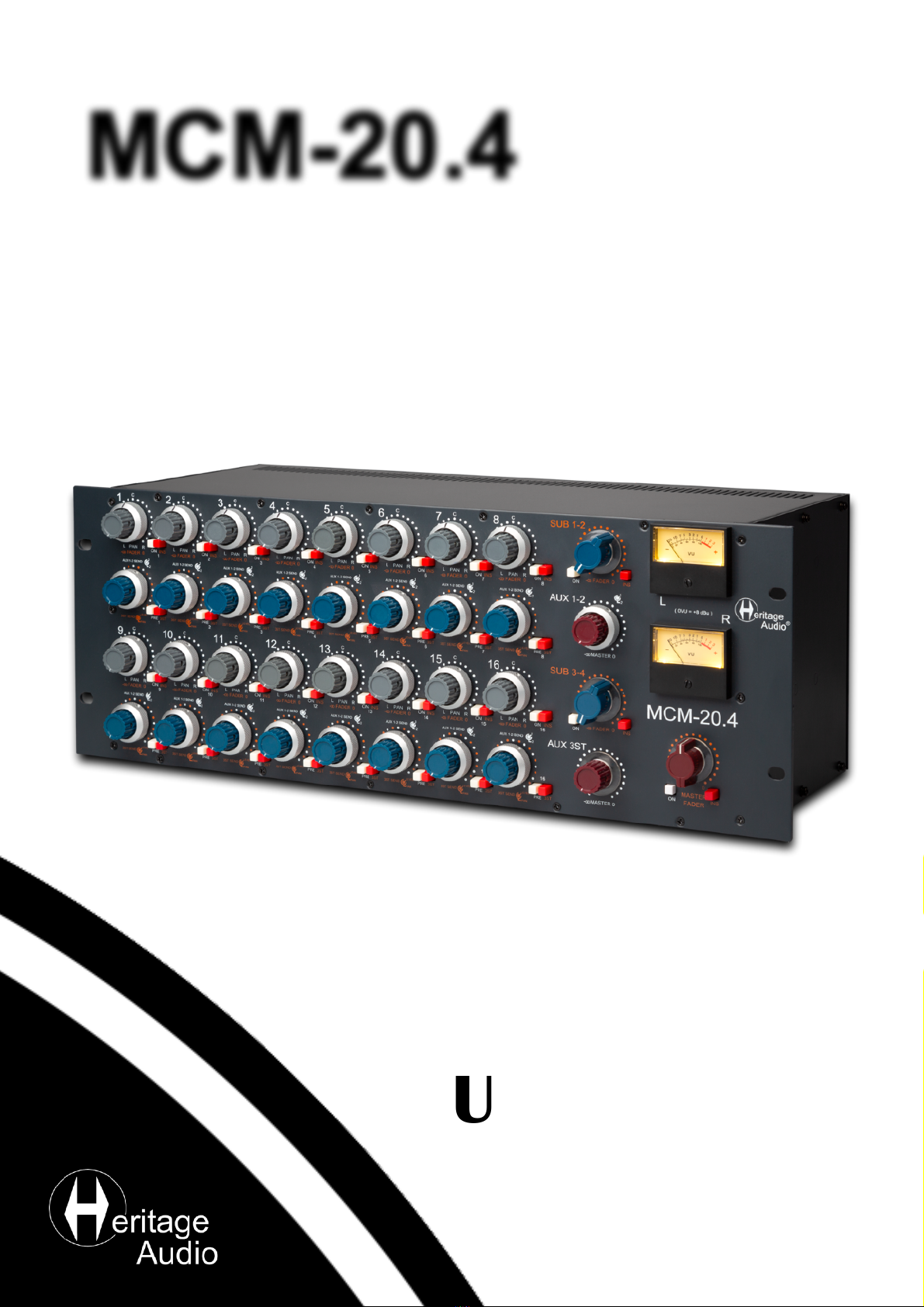
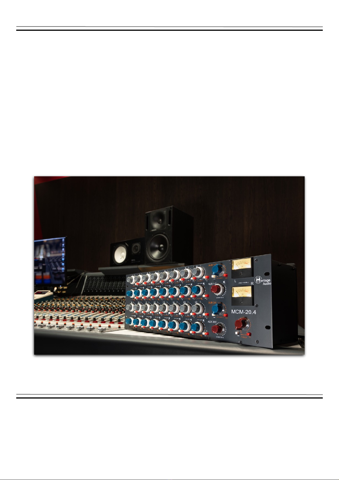
MCM-20.4
AC POWER CORD EU & US
POWER SUPPLY HA-PSU02
DESCRIPTION
The MCM-20.4 is a 20 x 4 channel summing mixer with Vintage-topology.
It employs a very unique and flexible configuration, offering 20 input channels arranged as: 16 implemented in 2 rows of
8 channels each with the remaining 4 assigned to the master section, hard panned left and right in pairs. These extra
AUX inputs come in handy when you want to stack several units or add another sub mixer in."Unlike classic consoles
employing a complicated switching matrix for subgroup assignment, the channels have a fixed assignment in groups of
eight. This arrangement not only makes the unit fit in a four-unit rack space, but greatly helps in making it affordable."
Each channel features center detent Pan and Fader concentric controls plus balanced insert and mute switches."The
insert send points always have the signal present, so they can alternatively be used as direct outputs for recording
without additional patch bays.
The 16 channels implemented on the front panel feature 3 aux sends, 2 mono and one stereo send. AUX 1 and 2 or 3ST
can be assigned on a per channel basis, but not all 4 sends can be used on the same channel at the same time."You
also have the ability to choose between a PRE or POST channel fader send for the AUXs which will allow you to
conveniently use them for FX sends as well as musician CUEs, once again, on a per channel basis. "Master send levels
are provided as well with their own fader, on/off switches and balanced inserts for even more control.
Each subgroup has its own stereo fader and an on/off switch plus a balanced insert point and all stereo subgroups are
passively summed into the master bus. The gain is restored by means of a ´73 style Class A, transformer coupled, mic
preamplifier, featuring a total of 4 transformers (2 in each channel). "These are some of our special custom Carnhill
transformers, of course to provide all the vintage flavor desired."This output stage is able to deliver a full +26 dBu
output."The master section is also provided with its own balanced, gold plated XLR insert points.
All connections on the back are made by DB 25 connectors following the TASCAM protocol, with the exception of the
master bus and monitor connections, which are by dedicated gold plated XLRs. And to top everything off there is a pair
of vintage style VU meters to monitor levels.
Comprising vintage quality sound with sophisticated routing options, the MCM-20.4 is the perfect partner for hybrid
setups, integrating analog gear with your DAW.
Lots has been written on the pros and cons between active (current) and passive (voltage) summing topologies. Some
may claim one is better than the other but the truth is that active summing is less susceptible to noise and voltage, while
passive summing has a nice, vintage sound associated with its gain makeup circuit.
The smart hybrid summing topology used in the MCM-20.4, where the channels are current-summed ( active ) into their
corresponding subgroups and the subgroups voltage summed ( passive ) into the master section, has proven to give
massive headroom and lower noise without making any compromises to its vintage characteristic sound. "Special care
has been taken on improving crosstalk and self-noise figures from those on vintage designs in order to accommodate
the new MCM mixers into the digital era.
3
GETTING STARTED
4
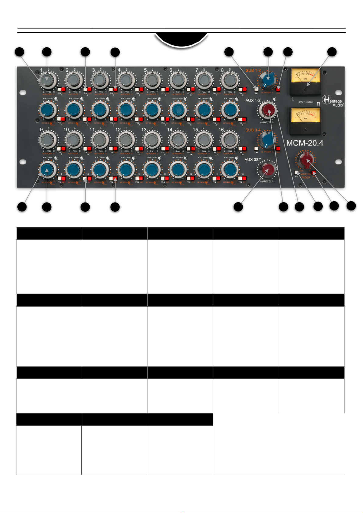
FRONT
1
2
3
4
5
6
7
8
9
10
11
12
13
14
15
16
17
18
1
2
3
4
5
PAN
Places the signal within the
stereo spectrum, left, center,
right or any setting in between.
FADER
Attenuates the signal sent to
the Master Bus from unity to
minus infinity. The control has a
stepped feel for easy recall of
settings."All the way clockwise
equals unity gain, while at 12
o’clock means an approximate
20 dB of attenuation. (Or -20
dB of gain).
ON (CHANNEL)
When pressed, the related input
is added to the subgroup bus.
INS (CHANNEL)
Turns the insert on. The insert
send always has the signal
present, while pressing the INS
switch activates the insert
return input.
ON (SUBGROUP)
When pressed, the output of
the subgroup is sent to the
Master Bus.
6
7
8
9
10
FADER
Attenuates the signal sent to
the Subgroup bus from unity to
minus infinity. All the way
clockwise equals unity gain,
while at 12 o’clock means an
a p p r o x i m a t e 2 0 d B o f
attenuation. (Or -20 dB of gain).
INS (SUBGROUP)
Turns the insert on. The insert
send always has the signal
present, while pressing the INS
switch activates the insert
return input.
VU Meters
Measures the average level at
the Master outputs.
0 VU = +8 dBu.
Reads post fader and post
insert.
AUX 2 / AUX 3ST PAN
Depending on the status of the
3ST button this outer ring either
adjusts the amount sent to AUX
2 or the Panning of Stereo AUX
3.
AUX 1 / AUX 3ST SEND
Depending on the status of the
3ST button this either adjusts
the amount sent to AUX 1 or
the Send of Stereo AUX 3. +
11
12
13
14
15
PRE
Changes the status of the AUX
sends from POST to PRE.
3ST
The 3ST button changes
control from AUX 1&2 to AUX
3.
AUX 3ST MASTER
Master volume send for Stereo
AUX 3.
AUX 1 MASTER
Master volume send for Stereo
AUX 1.
AUX 2 MASTER
Master volume send for Stereo
AUX 2.
16
17
18
14
5
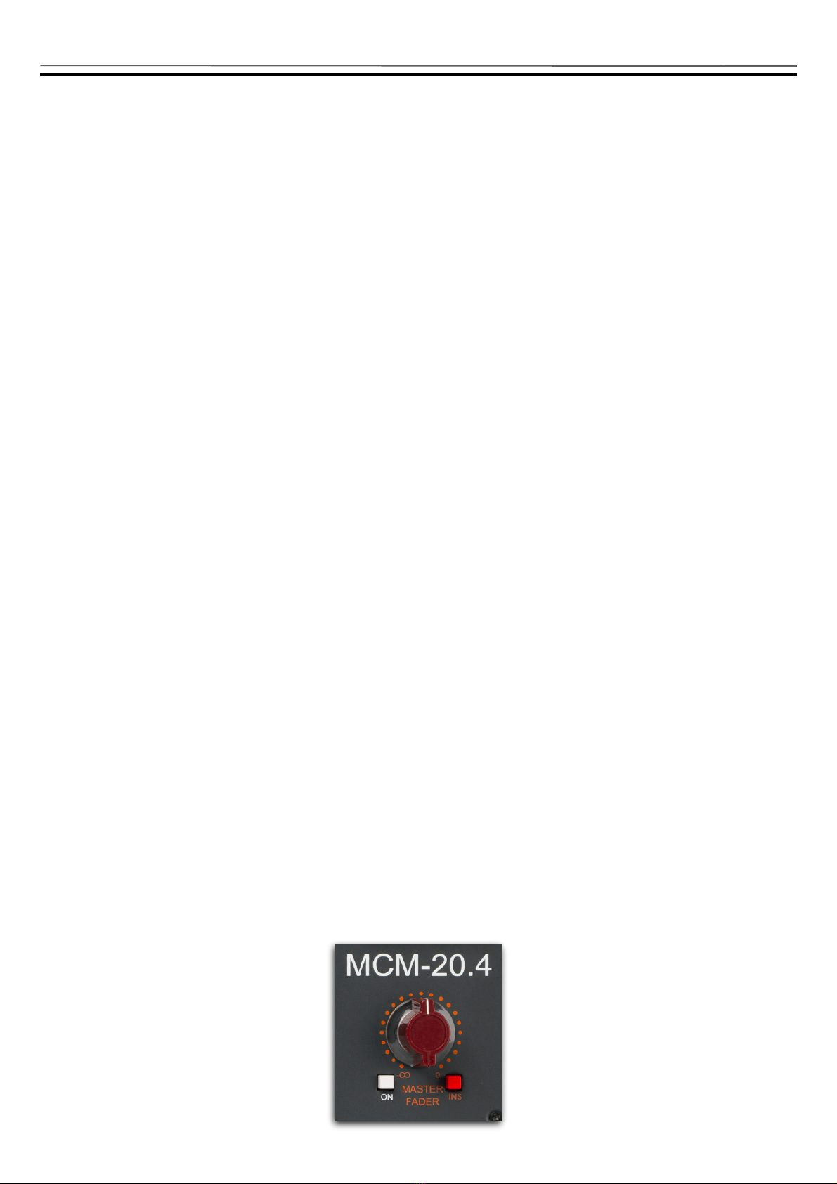
ON (MASTER)
When pressed, the output of
the Master is sent to the Output
connectors.
INS (MASTER)
Turns the insert on. The insert
send always has the signal
present, while pressing the INS
switch activates the insert
return input.
MASTER FADER
Attenuates the Mix’s output
from unity to minus infinity. The
control has a stepped feel for
easy recall of settings. All the
way clockwise equals unity
gain, while at 12 o’clock means
an approximate 20 dB of
attenuation.
INPUT GAIN SWITCH
5dB Steps From 30 to 80
HI SHELF ± 15dB at 12 kHz

5
All XLRs are:
Pin 1: GND!
Pin 2: Hot!
Pin 3: Cold
1
2
3
3
2
1
GND!
Hot (+)!
Cold (-)
MALE XLR
FEMALE XLR
REAR
3
4
1
2
5
7
6
9
10
11
12
13
* All XLR connections are Gold Plated
8
1
2
3
4
5
MIX OUTPUT
XLRs for Mix Output L and R.+
MONITOR OUTPUT
XLRs for Monitor Output L and
R.+
MASTER INSERT SEND
XLRs (2) for Master Insert Send
L and R.+
MASTER INSERT RETURN
XLRs (2) for Master Insert
Return L and R.+
INPUTS 1-8
DB25 for Channel Input 1-8.
6
7
8
9
10
INS. SENDS 1-8
DB25 for Insert sends 1-8.
INS. RETURNS 1-8
DB25 for Insert Returns 1-8.
POWER
5 pin XLR for the external HA-
PSU02 power supply unit.
SUBGROUP 1-4 INSERT
SENDS & AUX SENDS
DB25 for Subgroup 1-4 Insert
sends & Aux sends.+
SUBGROUP 1-4 INSERT
RETURNS & AUX INPUTS
DB25 for Subgroup 1-4 Insert
returns & Aux Inputs.+
11
12
13
14
15
INS. SENDS 9-16
DB25 for Insert sends 9-16.
INPUTS 9-16
DB25 for Channel Input 9-16.
INS. RETURNS 9-16
DB25 for Insert Returns 9-16.
INPUTS 1-32
DB25 (4) for Channel Input 1-8,
9-16, 17-24, 25-36.+
INS. RETURNS 1-32
DB25 (4) for Insert Returns 1-8,
9-16, 17-24, 25-36.+
GAIN STRUCTURE
"
The gain structure in the MCM-20.4 is quite simple and intuitive
with no compromises being made on the “secondary” inputs and
outputs, like the insert sends and returns.
Therefore, all connections are balanced and all outputs are
nominal +4 dBu and able to drive 600 Ω.
The gain structure is such that with all faders up, any input to any
output is unity gain.
+4 dBu at one channel input, fader all the way up, subgroup
fader all the way up, gives +4 dBu at the channel and subgroup
insert send points, and at the main send and output as well.
+4 dBu at the channel or subgroup insert returns will give +4 dBu
at the main send and output as well.
+4 dBu at the main insert return will give +4 dBu at the main
output.
+4 on a channel input, sends pre fader, will give +4 dBu at the
corresponding aux output.
6
8 CHANNEL
SUMMING
CHANNEL 1-8
SUBGROUP 1&2
MASTER
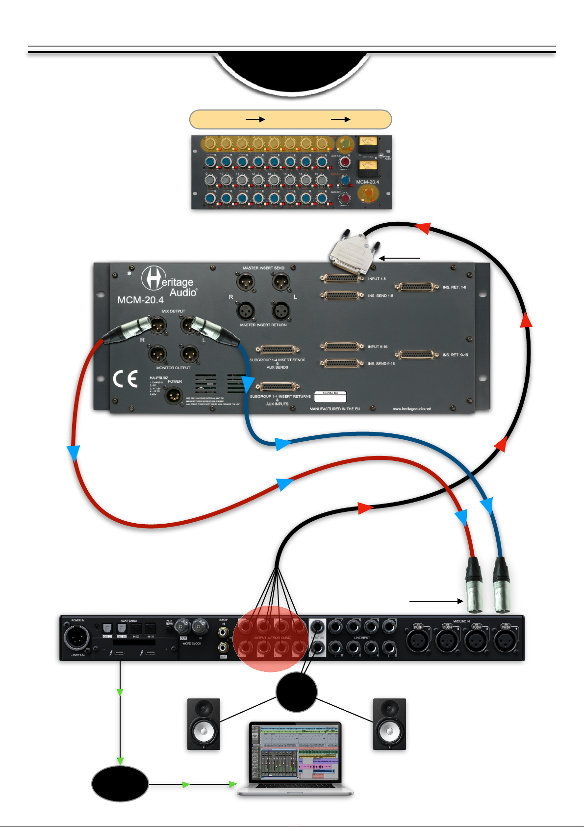
APPLICATIONS
MONITOR
SPEAKERS
THUNDERBOLT
COMPUTER
LINE
OUTPUTS
INPUT 1-8
INPUT 1-2 (L&R)

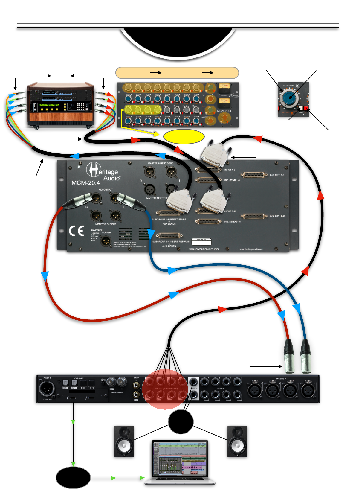
7
8 CHANNEL SUMMING
+ INSERTS
MONITOR
SPEAKERS
THUNDERBOLT
COMPUTER
LINE
OUTPUTS
INPUT 1-8 FROM DAW
INPUT 1-2 (L&R)
INPUT L&R
MASTER INPUT!
(COMPRESSOR)
CHANNEL 1-8 INSERTS!
(EQUALIZER)
INSERT SENDS 1-8 TO EQ
MIX OUTPUT TO DAW
(L&R)
INSERT RETURNS FROM EQ 1-8
CHANNEL 1-8
SUBGROUP 1&2
MASTER
OUTPUT L&R

8
16 CHANNEL TO
4 SUBGROUPS
THUNDERBOLT
COMPUTER
MONITOR L
MONITOR R
AUDIO INTERFACE
I/O 32x32
25-32
MIX OUTPUT (L&R)
TO CHANNELS
9 &10
TRACKS 1-16
TO CHANNELS 1-16
25-32
17-24
9 -16
1- 8
CHANNEL 1-16
SUBGROUP 1-4
MASTER
1- 8
9 -16
17-24
9
CHANNEL 1-8
SUBGROUP 1-4
MASTER
MONITOR
SPEAKERS
THUNDERBOLT
COMPUTER
LINE
OUTPUTS
INPUT 1-8
INPUT 1-2 (L&R)
8 CHANNELS TO
2 SUBGROUPS + FX
FX RACK
INPUTS
OUTPUTS
AUX SENDS 1, 2
&
3 STEREO
CHANNELS 9-12
(FX RETURNS)
AUX RETURNS 1, 2
&
3 STEREO
AUX 2 SEND LEVEL or
AUX 3 PAN CONTROL
AUX 1 SEND LEVEL
or AUX 3 SEND
Press to switch
between AUX 1&2
or 3ST(AUX3)
For FX leave unpressed
for POST fader send

10
CHANNEL 1-8
SUBGROUP 1-4
MASTER
MONITOR
SPEAKERS
THUNDERBOLT
COMPUTER
LINE
OUTPUTS
INPUT 1-8
INPUT 1-2 (L&R)
8 CHANNELS TO
4 SUBGROUPS/INSERTS
+ FX
FX RACK
INPUTS
OUTPUTS
AUX SENDS 1, 2
&
3 STEREO
CHANNELS 9-12
(FX RETURNS)
AUX RETURNS 1, 2
&
3 STEREO
CHANNEL 1-4 INSERTS!
(EQUALIZER)
INSERT SENDS 1-4 TO EQ
INSERT RETURNS 1-4 FROM EQ
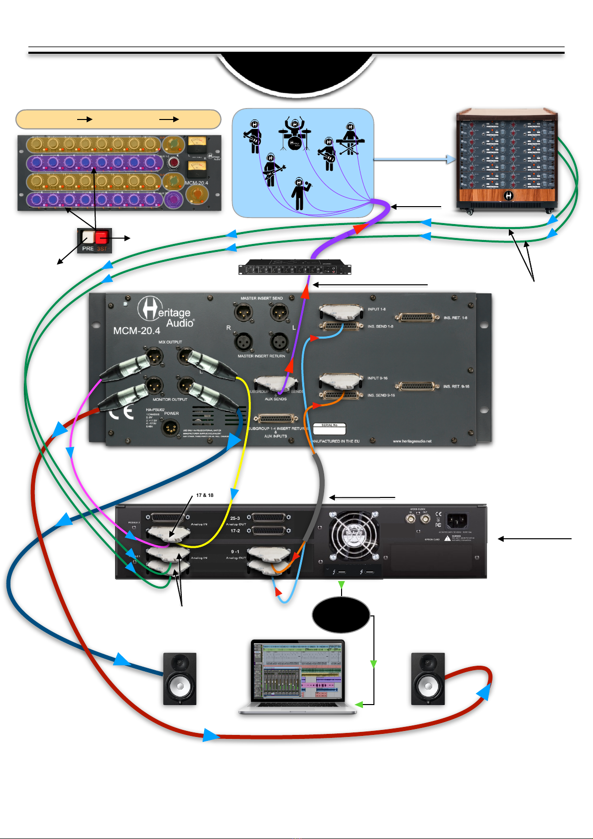
11
RECORDING WITH
CUE MIX
THUNDERBOLT
COMPUTER
MONITOR L
MONITOR R
AUDIO INTERFACE
I/O 32x32
25-32
TRACKS 1-16
TO CHANNELS 1-16
CHANNEL 1-16
SUBGROUP 1-4
MASTER
1- 8
9 -16
17-24
CHANNEL 1-16
PREAMPS
GROUP
INSTRUMENTS SIGNALS
1-16
MIX OUTPUT ( L&R )
TO CHANNELS
17 & 18
25-32
17-24
9 -16
1- 8
CHANNEL 1-16
PREAMP OUTPUTS
PREAMP OUTPUTS
TO DAW INPUTS
CUE MIX FOR
MUSICIANS
AUX SEND ( 3ST/PRE )
TO HEADPHONE AMP
Press to select stereo
AUX 3 ( 3ST )
Press to change from
POST to PRE send

1
INPUT 9
2
INPUT 10
3
INPUT 11
4
INPUT 12
5
INPUT 13
6
INPUT 14
7
INPUT 15
8
INPUT 16
All DB25 multi pin connectors are TASCAM protocol. This same protocol is also used by AVID* amongst many others,
and is a follows:
The list of the DB25 connectors used and their corresponding channels are as follows:
TASCAM DSUB
CHANNEL #
CHANNEL I/P
1-8
1
INPUT 1
2
INPUT 2
3
INPUT 3
4
INPUT 4
5
INPUT 5
6
INPUT 6
7
INPUT 7
8
INPUT 8
It is worth noting that, in order to avoid ground loops, the DB25 ground connections are lifted on the MCM-20.4
side, leaving the ground paths of your DB25 snakes only acting as shields and preventing any current returns.
TASCAM DSUB
CHANNEL #
CHANNEL I/P
1-8
Pin-out for TASCAM DB25 8 Channel Balanced Connector
CHANNEL INPUTS 9-16:
CHANNEL INPUTS 1-8:
H = HOT
C = COLD
G = GROUND
WIRING FOR DB25 CONNECTORS
12
CHANNEL INPUTS

13
1
INS SEND 9
2
INS SEND 10
3
INS SEND 11
4
INS SEND 12
5
INS SEND 13
6
INS SEND 14
7
INS SEND 15
8
INS SEND 16
TASCAM DSUB
CHANNEL #
INSERT SENDS
9-16
INSERT SENDS 9-16:
1
INS SEND 1
2
INS SEND 2
3
INS SEND 3
4
INS SEND 4
5
INS SEND 5
6
INS SEND 6
7
INS SEND 7
8
INS SEND 8
TASCAM DSUB
CHANNEL #
INSERT SENDS
1-8
INSERT SENDS 1-8:
INSERT SENDS
1
INS RETURN 9
2
INS RETURN 10
3
INS RETURN 11
4
INS RETURN 12
5
INS RETURN 13
6
INS RETURN 14
7
INS RETURN 15
8
INS RETURN 16
TASCAM DSUB
CHANNEL #
INS RETURNS
9-16
INSERT RETURNS 9-16:
1
INS RETURN 1
2
INS RETURN 2
3
INS RETURN 3
4
INS RETURN 4
5
INS RETURN 5
6
INS RETURN 6
7
INS RETURN 7
8
INS RETURN 8
TASCAM DSUB
CHANNEL #
INS RETURNS
1-8
INSERT RETURNS 1-8:
INSERT RETURNS
1
SUBGROUP INSERT SEND "1
2
SUBGROUP INSERT SEND 2
3
SUBGROUP INSERT SEND 3
4
SUBGROUP INSERT SEND 4
5
AUX 1 SEND
6
AUX 2 SEND
7
AUX 3L SEND
8
AUX 3R SEND
TASCAM DSUB
CHANNEL #
SUBGROUP INSERT SENDS &
AUX SENDS 1-4
SUBGROUP INSERT SENDS 1-4 AND AUX SENDS
SUBGROUP INSERT SENDS 1-4 AND AUX SENDS
1
SUBGROUP INSERT RETURN "1
2
SUBGROUP INSERT RETURN "2
3
SUBGROUP INSERT RETURN "3
4
SUBGROUP INSERT RETURN "4
5
AUX INPUT 1
6
AUX INPUT 2
7
AUX INPUT 3
8
AUX INPUT 4
TASCAM DSUB
CHANNEL #
SUBGROUP INSERT RETURNS &
AUX INPUTS 1-4
SUBGROUP INSERT RETURNS 1-4 AND AUX INPUTS
SUBGROUP INSERT RETURNS 1-4 AND AUX

SPECIFICATIONS
•Channel Input Impedance: Greater than 20 kΩ.
•Maximum channel input level: Greater than"+26 dBu.
•Maximum insert return input level: Greater than"+26 dBu.
•Maximum insert send level: Greater than +27 dBu, able to drive 600 Ω.
•Maximum output level: Greater than +26 dBu into 600 Ω.
•Frequency response: ±0.5 dB 20 Hz to 20 kHz.
•THD + N: Not more than 0.07% from 50 Hz to 10 kHz at +20 dBu output (22 Hz to 22 kHz bandwidth) into 600 Ω.
•Noise: All faders up, all subgroups in, measured at the main output, 22 Hz to 22 kHz. Better than -80 dBu.
14
MCM-20.4(POWER(SUPPLY(
The MCM range of summing mixers features a hybrid power supply concept, in a very similar way to famous On Slot
Technology (OST) employed in Heritage Audio´s successful 500 series enclosures range.
An external switching power supply enters the unit by means of a 5 pin XLR connector, where it is further filtered using
a PI configuration, using a big common mode choke.
Further, linear regulation stages are used. Different regulation is used for channels and buses, and output stages.

SIGNAL FLOW
INPUTS/INSERTS TLA AMP ON FADER PAN
SUBGROUP O/P 1
SUBGROUP O/P 2
1
2
3
4
5
6
7
8
CHANNEL 1-8 SECTION
INPUTS/INSERTS TLA AMP ON FADER PAN
SUBGROUP O/P 3
SUBGROUP O/P 4
1
2
3
4
5
6
7
8
CHANNEL 9-16 SECTION
15
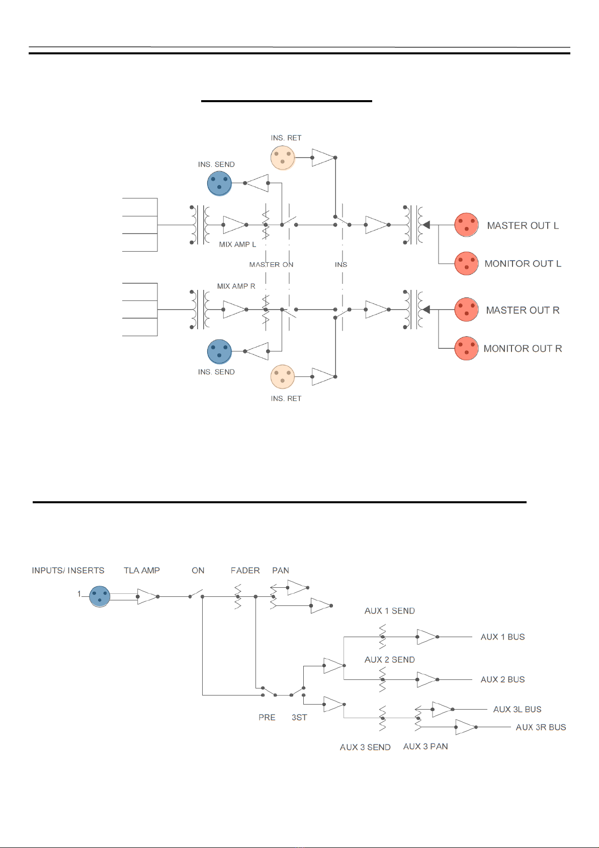
16
MASTER SECTION
DETAILED AUX SEND SECTION (SAME ALL CHANNELS)
SUBGROUP O/P 1
SUBGROUP O/P 3
AUX INPUT 1
AUX INPUT 3
SUBGROUP O/P 2
SUBGROUP O/P 4
AUX INPUT 2
AUX INPUT 4
MASTER OUT L
MASTER OUT R
MONITOR OUT L
MONITOR OUT R
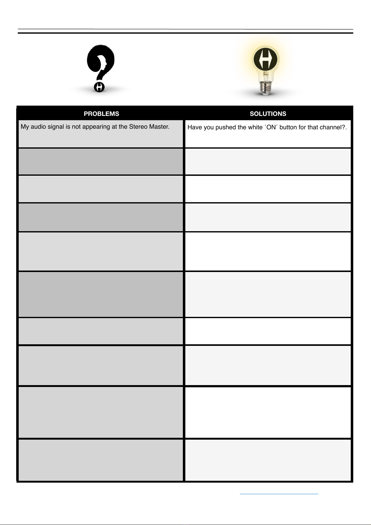
TROUBLE SHOOTING
17
PROBLEMS
SOLUTIONS
My audio signal is not appearing at the Stereo Master.
Have you pushed the white ´ON´ button for that channel?.
Still no audio signal at the Stereo Master.
You need to increase the inner grey knob for more
channel volume.
Yet still no signal arriving at the Stereo Master.+
You might need to increase the volume on the blue
Subgroup knob.
Even still, no signal arriving at the Stereo Master.+
Have you pushed the white ´ON´ button for that
Subgroup?
Even after checking all of that, the signal still isn´t arriving
at the Stereo Master.
Make sure you haven´t pushed an INS (Insert) button
without having anything inserted or the without the
patchbay"being ´normalled´.+
I´m only receiving audio on the ´Left´ side of the Stereo
Master.
Check to see if the outer ring ´PAN´ control has been set
to the extreme left side.""""""+
There is a center detent to assure equal signal to both
sides.+
There is no signal at all appearing at the Stereo Master.+
Double check your cables and connections.
I´d like to get a Direct Out from each channel."Is it
possible?+
Yes, of course."Just tap the INSERT SEND signal, which
is always active."This goes for Channels as well as
Subgroups and Stereo Master.+
I´d like to have a 12 channel bus for my drums."How
could I configure it?+
Just use the first 8 channels, sent to their Subgroup 1&2."
Take the output from Subgroup 1&2 and send it to
channels 9&10."Then at the Subgroup 3&4 you will have
channels 1-8 and channels 11-16."So that would allow
you a drum bus of up to 14 channels.+
I don´t want my AUX(FX) RETURNS hard panned Left or
Right. Is there another way to configure my setup to have
more control over their position in the stereo MASTER
Output?
Yes, by simply routing them to Channel Inputs you can
position them anywhere in the stereo field.
Just remember not to also send to the AUXs on those
channels as it will produce feedback loop.
LIMITED 2 YEAR WARRANTY
Heritage Audio MCM-20.4 Summing Mixer is warranted by Heritage Audio SL to be free from defects in materials and
workmanship for the period of 2 years to the original purchaser. In the event of such defects, the product will be repaired
without charge or, at our option, replaced with a new one if delivered to Heritage Audio prepaid, together with a copy of
the sales slip or other proof of purchase date. The warranty excludes problems due to normal wear, abuse, shipping
damage or failure to use the product in accordance with the specifications.
Heritage Audio shall not be liable for damages based upon inconvenience, loss of use of the product, loss of time,
interrupted operation or commercial loss or any other damages, whether incidental, consequential or otherwise.
This warranty is not transferable.
Heritage Audio and the Heritage Audio “H” logos are registered Trademarks owned and/or licensed by Heritage Audio.
REGISTRATION
18
Please visit our website:
WARRANTY STATEMENT
https://heritageaudio.com/registration/
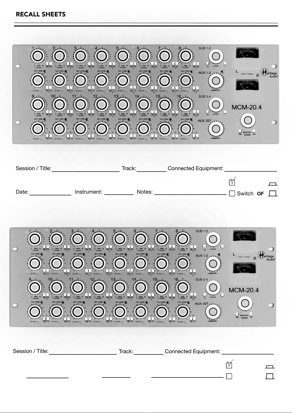
RECALL SHEETS
19
Session / Title: Track: Connected Equipment: !
Date: Instrument: Notes:
Switch ON
Switch OFF
SUB 1-2
SUB 3-4
MASTER
MASTER
FADER
FADER
FADER
FADER
FADER
FADER
FADER
FADER
FADER
FADER
FADER
FADER
FADER
FADER
FADER
FADER
FADER
FADER
PAN
PAN
PAN
PAN
PAN
PAN
PAN
PAN
PAN
PAN
PAN
PAN
PAN
PAN
PAN
PAN
PRE 3 ST
PRE 3 ST
PRE 3 ST
PRE 3 ST
PRE 3 ST
PRE 3 ST
PRE 3 ST
PRE 3 ST
PRE 3 ST
PRE 3 ST
PRE 3 ST
PRE 3 ST
PRE 3 ST
PRE 3 ST
PRE 3 ST
PRE 3 ST
L R
L R
L R
L R
L R
L R
L R
L R
L R
L R
L R
L R
L R
L R
L R
L R
MASTER
FADER
ON
INS
ON
INS
ON
INS
ON
INS
ON
INS
ON
INS
ON
INS
ON
INS
ON
INS
ON
INS
ON
INS
ON
INS
ON
INS
ON
INS
ON
INS
ON
INS
ON
INS
AUX 1-2 SEND
AUX 1-2 SEND
AUX 1-2 SEND
AUX 1-2 SEND
AUX 1-2 SEND
AUX 1-2 SEND
AUX 1-2 SEND
AUX 1-2 SEND
AUX 1-2 SEND
AUX 1-2 SEND
AUX 1-2 SEND
AUX 1-2 SEND
AUX 1-2 SEND
AUX 1-2 SEND
AUX 1-2 SEND
AUX 1-2 SEND
3ST SEND
3ST SEND
3ST SEND
3ST SEND
3ST SEND
3ST SEND
3ST SEND
3ST SEND
3ST SEND
3ST SEND
3ST SEND
3ST SEND
3ST SEND
3ST SEND
3ST SEND
3ST SEND

Table of contents
Other Heritage Audio Music Mixer manuals


