Box spring Hilo OPERATING INSTRUCTIONS
page 8 of 62
LIST OF FIGURES
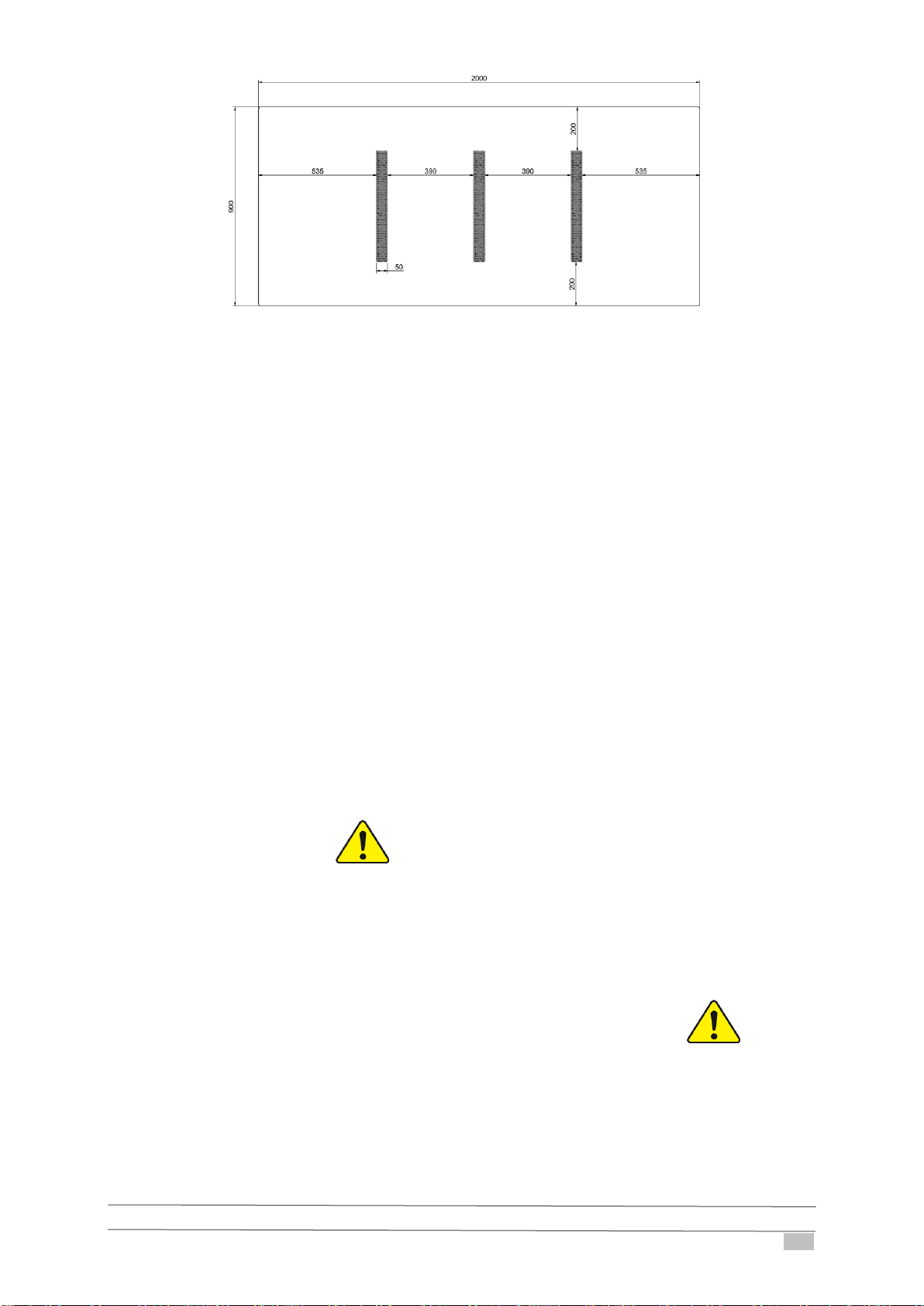
Figure 1.1: Velcro strips for the mattress............................................................................................................... 11
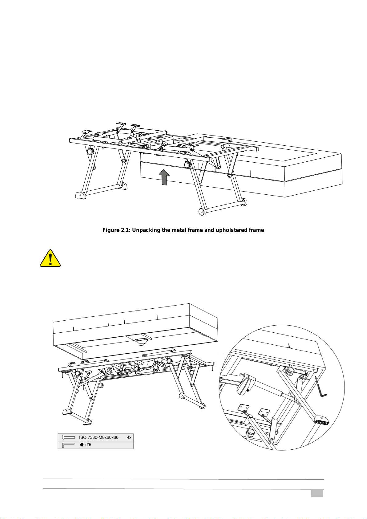
Figure 2.1: Unpacking the metal frame and upholstered frame............................................................................. 13
Figure 2.2: Fixation of the upholstered frame to the metal frame .......................................................................... 13
Figure 2.3: Fixation of the head and foot end........................................................................................................ 14
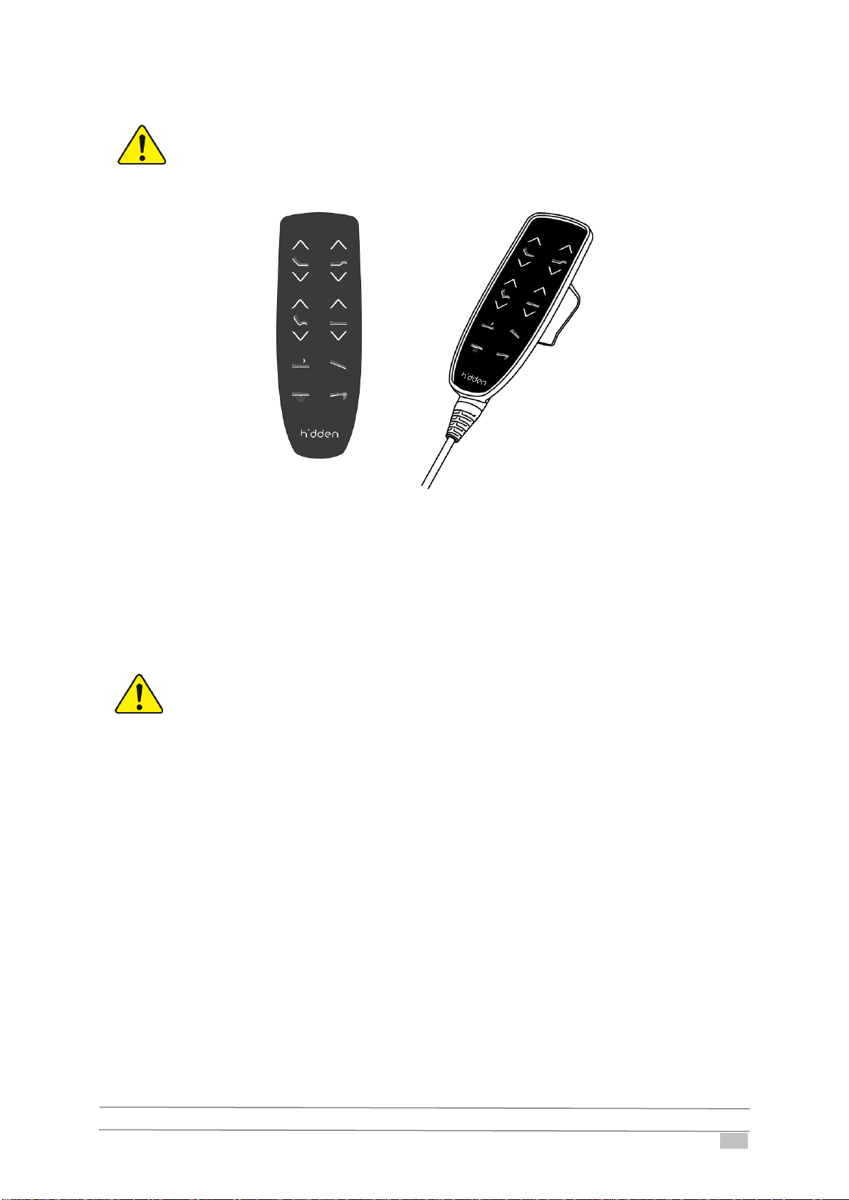
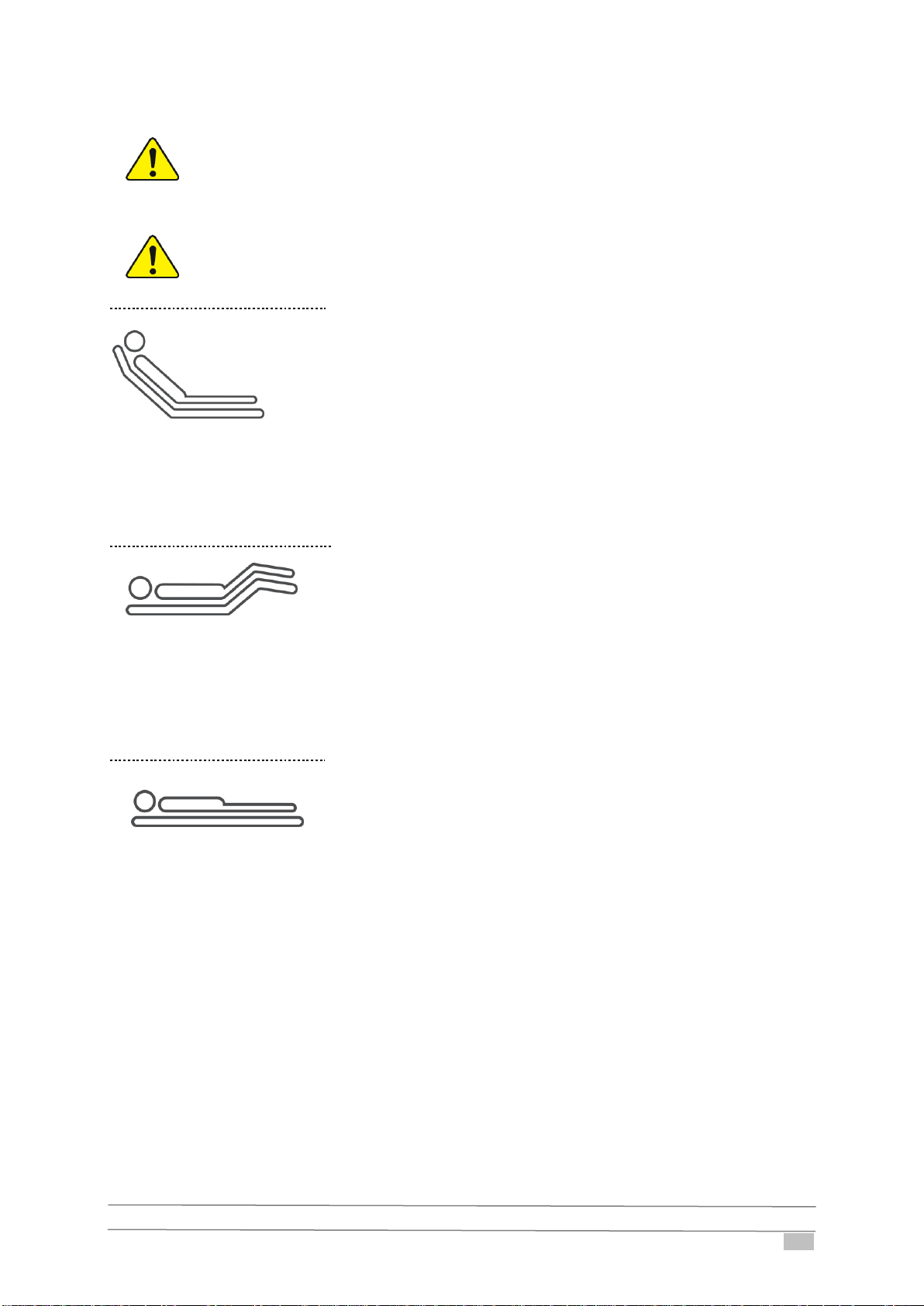
Figure 2.4: Hand switch......................................................................................................................................... 15
Figure 2.5: Depiction of the electric HL-adjustment............................................................................................... 17
Figure 2.6: Nightlight under the bed ...................................................................................................................... 19
Figure 2.7: Reset procedure.................................................................................................................................. 19
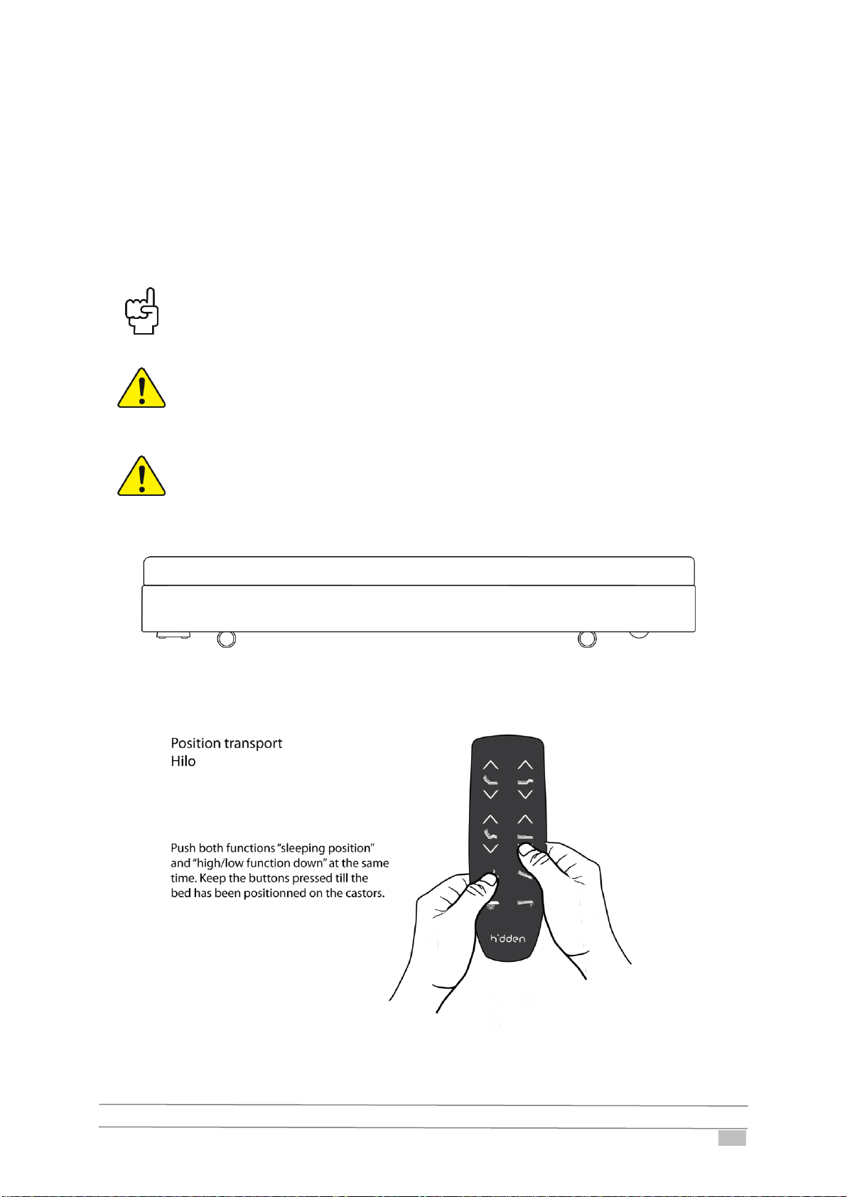
Figure 2.8: Transport position of the Hilo (1)......................................................................................................... 20
Figure 2.9: Transport position of the Hilo (2)......................................................................................................... 20
Figure 3.1: Position of the positioning pin: fixation on the left side of the bed ....................................................... 21
Figure 3.2: Position of the positioning pin: fixation on the right side of the bed ..................................................... 22
Figure 3.3: Dimensions of the predrilled holes for fixation of the accessory holder............................................... 22
Figure 3.4: Fixation of the accessory holder.......................................................................................................... 23
Figure 3.5: Installation of the lifting pole in the accessory holder........................................................................... 24
Figure 3.6: Exterior limits of the lifting pole............................................................................................................ 25
Figure 3.7: IV Rod ................................................................................................................................................. 26
Figure 3.8: How to install the mattress support...................................................................................................... 26
Figure 3.9: Bed connector ..................................................................................................................................... 27
Figure 3.10: Placing the bed connector................................................................................................................. 27
Figure 3.11: Putting the first bed on the bed connector......................................................................................... 28
Figure 3.12: Distance between both beds ............................................................................................................. 28
Figure 3.13: Lifting the backrest of the second bed............................................................................................... 29
Figure 3.14: Putting the second bed on the bed connector................................................................................... 29
Figure 3.15: Functioning of the lowerable stand-up aid Lox .................................................................................. 30
Figure 3.16: How to install the removable stand-up aid Lox.................................................................................. 31
Figure 5.1: Dimensions Hilo box-spring bed.......................................................................................................... 36
Figure 5.2: Most important manipulation data of the Boxspring Hilo...................................................................... 36
Figure 6.1: Circuit diagram Hilo............................................................................................................................. 39
Figure 6.2: How to open the cover of the control box............................................................................................ 40
Figure 6.3: Led-indication for the control box CO61.............................................................................................. 41
Figure 9.1: Axle and axle retaining ring ................................................................................................................. 44
Figure 9.2: Cable clamp ........................................................................................................................................ 45
Figure 9.3: Led-indication on a BA19 battery......................................................................................................... 46
Figure 9.4: Led-indication on a BA21 battery......................................................................................................... 48
Figure 9.5: Release of the strain relief................................................................................................................... 49
Figure 9.6: Replacement of the mains cable in the control box............................................................................. 50
Figure 9.7: Fastening of the strain relief................................................................................................................ 50
Figure 9.8: How to replace the control box............................................................................................................ 50