Highlander Pro Acoustic Mix DI User manual
Owners Manual

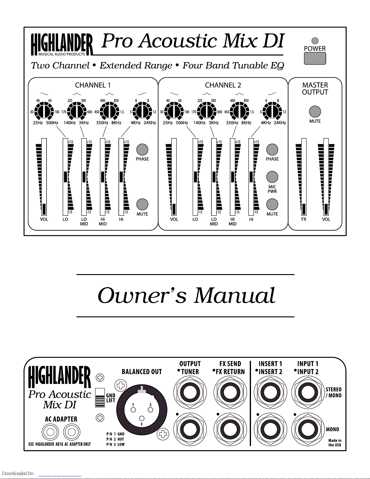
The Pro Acoustic Mix DI
An Acoustic Powerhouse

Welcome
Welcome to the Highlander Pro Acoustic Mix DI and thank you for placing your
trust in Highlander Products.
The Pro Acoustic Mix DI offers a level of audio uality and versatility that until
now could only be obtained by purchasing bulky, rack mount e uipment. Whats
more, the Pro Acoustic Mix DI is small enough to fit in the accessory compart-
ment of many guitar cases and can be powered by batteries, making it com-
pletely portable (120 hours from two 9V batteries).
The Pro Acoustic Mix DI includes a Two Channel Mixer with Four Band Tun-
able EQ on each Channel, Phase Reverse Switching, Mic Power, Effects Loop,
Integrated DI (XLR, balanced output) and much more. The Ultra-Low Noise,
Extended Range Electronics deliver the ultimate in warmth and clarity. Ergo-
nomically engineered to provide unsurpassed ease of use, this is truly an Acous-
tic Powerhouse.
Taking a little time to familiarize yourself with the workings of the Pro Acoustic
Mix DI will help you gain the maximum benefit from this powerful tool.
Best wishes from the staff at Highlander.
870 CAPITOLIO WAY, UNIT 3 · SAN LUIS OBISPO, CA 93401 USA
TEL: 805.547.1410 · FAX: 805.547.1228
U.S. & CANADA TOLL F EE: 888.658.1819
EMAIL: [email protected]
WEBSITE: highlanderpickups.com

Important Information
Retain this Manual:
The operating instructions should be read before the unit is operated.
Water and Moisture:
The unit should not be used near water (e.g. near a sink, etc.) or exposed to rain, sleet or snow.
Care should be taken so that liquids are not spilled into the enclosure.
Mechanical:
Do not expose the unit to excessive vibration including loudspeakers. Care should be taken so
that objects do not fall on the unit. The unit should not be dropped. void situations where any
cables attached to the unit could cause someone to trip and hurt themselves or cause the unit
to fall.
Heat:
The unit should not be situated in direct sunlight and should be kept away from heat sources
such as radiators, stoves or other appliances including amplifiers that produce heat.
Grounding:
The unit is grounded by the audio equipment it is plugged into. Make sure that the audio
equipment that the unit is plugged into is properly grounded.
Power Source:
The unit should be connected to a power supply only of the type described in the operating
instructions or as marked on the unit and its C dapter. Do not stand on the power cable.
Cleaning:
The unit should be cleaned using a slightly damp (almost dry) soft cloth. Do not use cleaning or
polishing products. Do not spray the unit with water or any liquid cleaners.
Non-Use Periods:
The C Power dapter should be unplugged from the outlet, and the batteries should be
removed when the unit is not going to be used for long periods of time.
Servicing:
The user should not attempt to service the unit beyond what is described in the operating
instructions. ll servicing should be referred to qualified personnel.

Contents
Quick Start .....................................................................................................6
Power and Connections ................................................................................................. 6
Basic Settings ................................................................................................................ 7
Front Panel Controls .....................................................................................8
Back Panel Connectors .............................................................................. 10
Input Channels in Detail.............................................................................. 12
Recommended Types of Pickups ................................................................................ 12
Instrument icrophones............................................................................................... 12
Channel Volume Controls ............................................................................................ 12
Channel Inserts ............................................................................................................ 12
Phase Reverse ............................................................................................................. 13
The EQ ......................................................................................................................... 13
Extended Range EQ .................................................................................................... 14
Tunable EQ .................................................................................................................. 14
Using Tunable EQ ........................................................................................................ 15
Artistic Use of EQ ................................................................................................. 15
Using EQ to deal with problems ........................................................................... 15
Pitch to Frequency able ............................................................................ 16
Examples of Pitch to Frequency conversion ................................................................ 16
Master Output in Detail ............................................................................... 17
Output Level ................................................................................................................. 17
aster ute ................................................................................................................. 17
Tuner Output ................................................................................................................ 17
The FX Loop (Special Effects) ..................................................................................... 18
Unbalanced Output ...................................................................................................... 18
Balanced Output .......................................................................................................... 18
Ground Lift Switch ........................................................................................................ 18
Unbalanced and Balanced Connections ...................................................................... 19
Unbalanced Connections ..................................................................................... 19
Balanced Connections ......................................................................................... 19
Power ...........................................................................................................20
AC Adapter ................................................................................................................... 20
Using Batteries ............................................................................................................. 20
Installing Batteries ........................................................................................................ 20
LED Power Indicator and Battery Level onitor .......................................................... 20
Block Diagram .............................................................................................22
ech Specs................................................................................................... 23
Extended Response ..................................................................................................... 23
Table of contents


