Hillphoenix Adaptapak ADP-M0048-L0000 Owner's manual

INSTALLATION AND OPERATION
Contents
Copyright© 2018 by Hillphoenix
All rights reserved. No part of this document may be reproduced or transmitted in any form or by any means—
electronic or mechanical, including photocopying or recording; or any other information storage and retrieval
system—without express written permission from Hillphoenix.
P096412C ∙ V2 10/31/2018
Due to our commitment to continuous improvement, all specifications shown in this manual are subject to change without notice.
Important Notices............................................... 2
General Information ............................................ 3
AdaptaPAK®Product Information.............................. 5
Two Fan AdaptaPAK®Unit................................... 4
Three Fan AdaptaPAK®Unit................................. 5
Two Fan AdaptaPAK®Unit....................................... 8
Three Fan AdaptaPAK®Unit................................... 10
Four Fan AdaptaPAK®Unit.................................... 12
AdaptaPAK®Models Overview................................ 14
Key to Codes in AdaptaPAK®Model Numbers................ 16
DX Refrigeration Systems..................................... 17
Refrigeration System Components ........................ 17
multiMAXTM Controller for AdaptaPAK® ...................... 21
multiMAXTM Controller I/O Connections..................... 23
AdaptaPAK®Installation ...................................... 29
Systems Start-Up Checklist................................. 43
AdaptaPAK®Maintenance and
Troubleshooting Procedures................................... 45
2AdaptaPAK® Parallel Refrigeration System
Thank You!
The Hillphoenix AdaptaPAK® refrigeration system provides customers with a compact refrigeration
package designed to remove heat from both medium- and low-temperature loads. Such a system,
as selected by the customer, is built to closely match the necessary heat removal capacity. It is a
DX system with a refrigerant charge matched to the needs of the facility where it is installed. Each
The fans and condensing units are sized to provide for sufficient heat rejection under the most
demanding ambient conditions.
Each Unit utilizes a comprehensive controls system which monitors the refrigeration system to
minimize energy and optimize performance.
The controls system allows field networking to the store’s Building Management System. In
addition, local networks may be installed to create coordinated case defrosts on a common
schedule, similar to traditional refrigeration circuits of traditional remote systems.
Important Notices
Hillphoenix designates important information in all Hillphoenix installation and operations
handbooks with alert symbols. These notices provide information about potential dangers to
personal health and safety – as well as case damage – if these instructions are not carefully
followed.
Service Notes
To ensure optimum unit performance, we strongly recommend that Hillphoenix refrigeration
units be installed and serviced by trained and qualified technicians who have experience working
with commercial refrigerated systems, piping, display cases and storage cabinets. For a list of
Hillphoenix-authorized installation and service contractors, visit hillphoenix.com/dealer-group.
ATTENTION!
Indicates important information that is
critical to proper system performance.
CAUTION!
Indicates the threat of potential injury if all
instructions are not followed carefully.
DANGER!
Indicates an immediate threat of serious injury
or death if all instructions are followed carefully.

3
AdaptaPAK® Parallel Refrigeration System
General Information
This manual covers general installation and operational information for the Hillphoenix AdaptaPAK® refrigeration
system. Hillphoenix recommends you retain a copy for future reference
Store Conditions
Hillphoenix refrigeration systems are designed to operate in ASHRAE conditions: a climate-controlled store that
maintains a 75 oF (24 oC) interior temperature and a maximum 55% relative humidity. System and display case
operation will be adversely affected by exposure to excessively high ambient temperatures and/or humidity.
Receiving Units
Inspect received units carefully. In the event of shipping damage and/or shortages, please contact the Hillphoenix
Service parts Department at 800-283-1109.
Unit Damage
Claims for damage must be: (1) noted on either the freight bill or the express reciept, and (2) signed by the carrier’s
agent. Otherwise, the carrier may refuse the claim. If damage becomes apparent after the cases are unpacked,
retain all packing materials and submit a written request (along with photos of the damage) to the carrier for
inspection within 14 days of receipt of the unit.
Missing Items
Hillphoenix refrigeration systems are inspected before shipping to ensure the highest level of quality. Any claim for
missing items must be made to Hillphoenix within 48 hours of receipt of cases.
Technical Support
For technical support issues regarding this unit, contact the Hillphoenix Systems Division Technical Support
at 1-800-518-6630.
Ordering Unit Parts
If you need to contact Hillphoenix regarding specic xtures or parts, call 800-283-1109 and ask for a Service Parts
If the part does not have a barcode afxed to it, provide the following information:
• Model number and serial number of the unit for which the part is intended. The serial number may be found
on the serial plate located on the unit.
• Length of the part, if applicable.
• Color of part (if painted) or color of polymer part.
• Whether the part is for a left-handed or a right -handed application.
• Quantity of parts
• Ship-to location.
If Hillphoenix Service Parts decides that a part must be returned instead of scrapped, you will be issured a Return
Material Authorization number.
Hillphoenix Part Barcode
Part Number located at bottom left.

4AdaptaPAK® Parallel Refrigeration System
5
AdaptaPAK® Parallel Refrigeration System
Section 1:
AdaptaPAK®Product Information
Hillphoenix offers the AdaptaPAK® range of parallel refrigeration systems to
provide customers with an effective alternative to centralized parallel systems.
The various versions of AdaptaPAK® are designed to meet a wide range of
requirements.
AdaptaPAK® Features and Benets
The Hillphoenix AdaptaPAK® parallel system works like any conventional DX refrigeration system, with the main
difference being that there may be one or more individual systems required to serve the full range of refrigeration
loads in a store. The arrangement is different than the installation of one, single, large centralized refrigeration
system, the multiple condensers are an integral part of the unit.
It is also designed specically to improve on the
performance of low and/or medium temperature
refrigeration installations in drug stores, convenience
stores, and other smaller-footprint retail establishments.
An AdaptaPAK® parallel system shares suction,
discharge, and an integrated condenser across several
compressors. As a result, compressor capacity may
be varied to match the required loads—a much more
efcient design.
Multiple, single units with compressors running
constantly at maximum output waste energy and reduce
component life. Parallel installations, on the other hand,
do just the opposite. Because compressor capacities are allowed to vary to match refrigeration loads, there is a
marked savings of energy utilized—20% or more compared to single compressor unit—as well as positive benets on
the live of all system components.
There is also a savings in initial capital outlay with a parallel system. Shared suction, discharge, and an integrated
condenser among compressors virtually guarantees cost savings versus the expense inherent in purchasing
several, self-contained single units. Plus, the single point electrical connection along with a single roof curb and roof
penetration add up to additional savings in installation costs.
Hillphoenix AdaptaPAK® parallel systems are available in a 2 fan unit, a 3 fan unit, and a 4 fan conguration. The
compressors would be arranged in up to two suction groups, with one loop per suction group.

6AdaptaPAK® Parallel Refrigeration System
Whether a 2 fan unit or a 3 fan unit, the AdaptaPAK® system will arrive fully designed for your load conguration,
and ready for placement at the site in your designated pad or roof location. Placement would most commonly be
performed with a cable/rope with proper rigging (refer to drawings for details).The remaining tasks would include
charging with refrigerant, making electrical connections, and completing the connection of the AdaptaPAK® unit up
to your refrigeration loads.
Dimensions of AdaptaPAK® Units
The 2 fan unit is 139 1/4 inches long by 50 1/2 inches wide by 51 1/4 inches high.
The 3 fan unit is 180 inches long by 50 1/2 inches wide by 51 1/4 inches high.
The 4 fan unit is 220 inches long by 50 1/2 inches wide by 51 1/4 inches high.
Clearances for AdaptaPAK® Units (2 fan and 3 fan)
Air Intake: 36 inches recommended
Air Exhaust: 36 inches recommended
Piping Clearance: 36 inches (minimum) recommended
Hinged Front Door: 36 inches (outward from door) by 50 inches (width)
NEC Electrical: 36 inches (outward from door) by 50 inches (width)
Weights of AdaptaPAK® Units (2 fan and 3 fan)
Fans Compressors Estimated Weight
2 4 3,000 lbs
3 6 3, 500 lbs
4 8 4,000 lbs
AdaptaPAK® Units’ Standard Features
The following features are provided as standard equipment on AdaptaPAK® units (2 fan, 3 fan, and 4 fan):
• Pre-painted, galvanized steel cabinet (pueblo tan).
• Refrigerants available are R-407A and R-448A/R-449A
• Uncoated copper tube/aluminum n condenser coil.
• Main power is 208V.
• Scroll compressors (only).
• Digital scroll compressor as the lead compressor per suction group
• Receiver includes analog liquid level indicator/alarm.
• Replaceable core lter/drier and sight glass.
• Oversized receiver.
• Fixed speed AC condenser fan motors.

7
AdaptaPAK® Parallel Refrigeration System
• One low pressure control per suction group.
• One high pressure control per compressor.
• OMB electronic oil oat per compressor.
• Discharge centrifugal oil separator with integral oil reservoir.
• Through-the-door power disconnect for serviceability.
• Phase loss monitor with brownout protection.
• IEC contactors for all compressors.
• Convenient service control switches for compressors.
• Off cycle and electric defrost are available.
• Remote defrost panel (when required) will be shipped loose for eld installation.
• Hillphoenix multiMAX™ control system installed in control panel.
Note that the AdaptaPAK® units are designed for outdoor placement, and thus are constructed with a painted
steel nish for durability. Each unit has its own designated lifting points to facilitate easy lifting and site placement.
Removable panels and hinged access doors provide for both equipment protection and serviceability.
In addition to the standard equipment detailed in the list above, customer-selectable options may have been include
on the unit being installed. Please check the customer order or the Hillphoenix acknowledgement to determine
which custom options have been provided for your specic unit. These options are detailed below.
Available AdaptaPAK® Unit Options
The following features are available as optional equipment on AdaptaPAK® units:
• Variable speed EC condenser fan motors.
• 460V main power.
• Electron coated condenser coil.
• Heat reclaim valve package (remote only).
• Cold Weather Package - split condenser and heated/insulated receiver
• Hail guard.
• Digital liquid level indicator/alarm.
• Low-pressure control per compressor.

8AdaptaPAK® Parallel Refrigeration System
Two Fan AdaptaPAK® Unit
As noted earlier, this unit has two condenser fans and up to two condensers sized appropriately for the design-
specied refrigeration heat removal loads.
The dimensions of the two fan unit, as well as the required clearances for operation and serviceability were provided
earlier in this section.
Of course, the design-specied refrigeration heat removal load would be the determining the number/capacity of the
compressors, the receiver size, and the details of the parallel system.
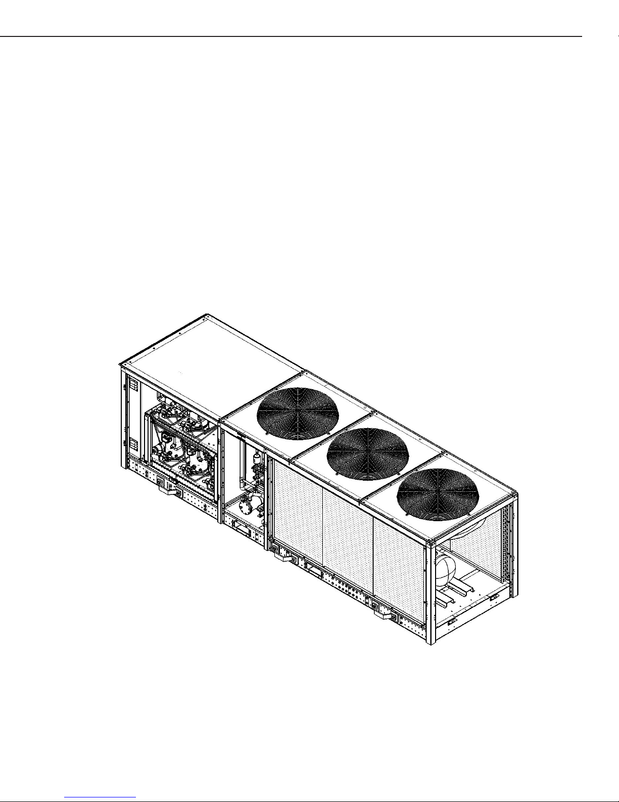
A rear, isometric view of the two fan AdaptaPAK® unit is shown below. Note that on this drawing the access panels
and doors have been removed.
Note that the condenser coil(s) are located at the rear of the unit. The two fans on the top of the unit would draw
ambient outdoor air in through the condenser coil(s) and exhaust that air through the fans on top. As noted
previously, sufcient clearances are required for proper unit operation.
Two Fan AdaptaPAK® Unit
Rear Isometric View
Access Panels Removed
For Clarity

9
AdaptaPAK® Parallel Refrigeration System
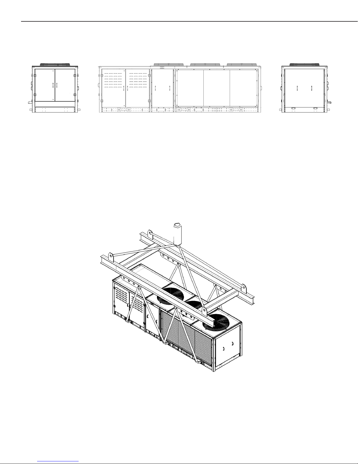
The layout drawing provided below shows the front view of the two fan unit, as well as the two end views.
Also, as previously noted. a drawing is supplied which depicts the lifting points on the two fan AdaptaPAK® unit, and
details an appropriate lifting jig and the necessary rigging for the cable/rope to perform a level lift and successful
placement of this unit.
Two Fan AdaptaPAK® Unit
LEFT END VIEW FRONT VIEW RIGHT END VIEW
Lifiting
Detail
Two Fan AdaptaPAK® Unit
10 AdaptaPAK® Parallel Refrigeration System
Three Fan AdaptaPAK® Unit
This unit has three condenser fans and two condensers sized appropriately for the design-specied refrigeration
heat removal loads.
The dimensions of the three fan unit, as well as the required clearances for operation and serviceability were
provided earlier on page two.
Of course, the design-specied refrigeration heat removal load would be used in determining the number/capacity of
the compressors, the receiver size, and the details of the parallel system.
A rear, isometric view of the three fan AdaptaPAK® unit is shown below. Note that on this drawing the access panels
and doors have been removed
Note that the condenser coil(s) are located at the rear of the unit. The three fans on the top of the unit would
draw ambient outdoor air in through the condenser coil(s) and exhaust that air through the fans on top. As noted
previously, sufcient clearances are required for proper unit operation.
Three Fan AdaptaPAK® Unit
Rear Isometric View
Access Panels Removed
For Clarity
11
AdaptaPAK® Parallel Refrigeration System
The layout drawing provided below shows the front view of the three fan unit, as well as the two end views.
Also, as previously noted. a drawing is supplied which depicts the lifting points on the three fan AdaptaPAK®
unit, and details an appropriate lifting jig and the necessary rigging for the cable/rope to perform a level lift and
successful placement of this unit.
LEFT END VIEW FRONT VIEW RIGHT END VIEW
Three Fan AdaptaPAK® Unit
Lifiting
Detail
Three Fan AdaptaPAK® Unit
12 AdaptaPAK® Parallel Refrigeration System
Four Fan AdaptaPAK® Unit
This unit has four condenser fans and two condensers sized appropriately for the design-specied refrigeration heat
removal loads.
The dimensions of the four fan unit, as well as the required clearances for operation and serviceability were provided
earlier on page two.
Of course, the design-specied refrigeration heat removal load would be used in determining the number/capacity of
the compressors, the receiver size, and the details of the parallel system.
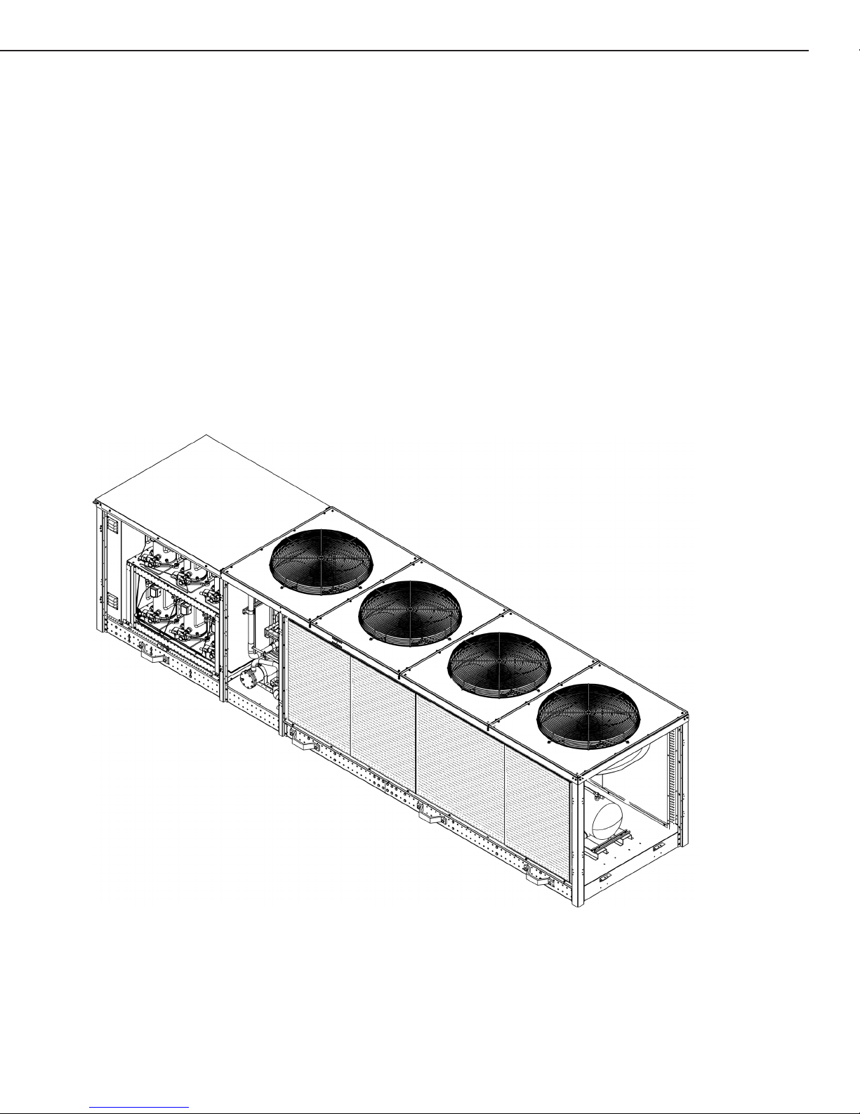
A rear, isometric view of the four fan AdaptaPAK® unit is shown below. Note that on this drawing the access panels
and doors have been removed
Note that the condenser coil(s) are located at the rear of the unit. The four fans on the top of the unit would
draw ambient outdoor air in through the condenser coil(s) and exhaust that air through the fans on top. As noted
previously, sufcient clearances are required for proper unit operation.
Four Fan AdaptaPAK® Unit
Rear Isometric View
Access Panels Removed
For Clarity
13
AdaptaPAK® Parallel Refrigeration System
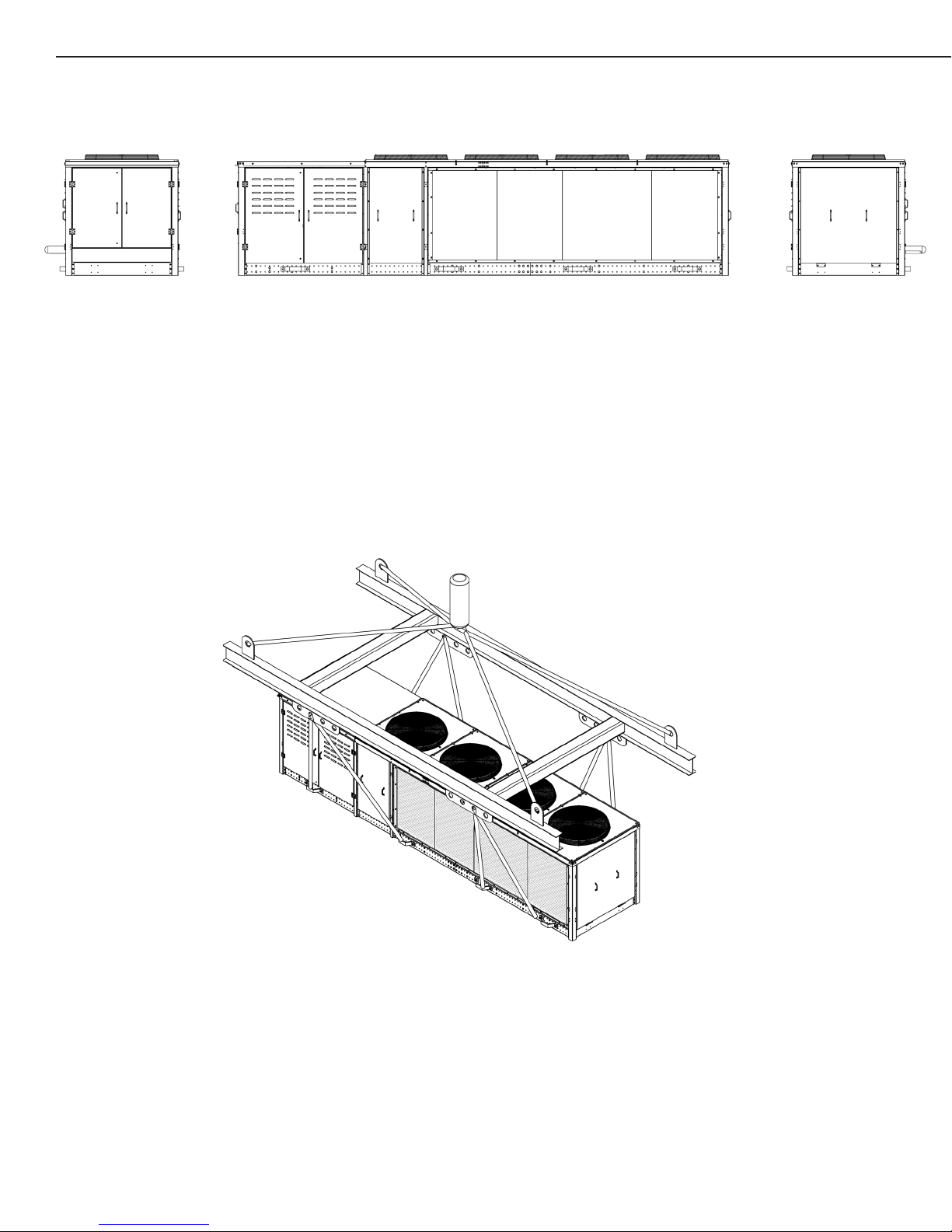
The layout drawing provided below shows the front view of the four fan unit, as well as the two end views.
Also, as previously noted. a drawing is supplied which depicts the lifting points on the four fan AdaptaPAK® unit, and
details an appropriate lifting jig and the necessary rigging for the cable/rope to perform a level lift and successful
placement of this unit.
LEFT END VIEW FRONT VIEW RIGHT END VIEW
Four Fan AdaptaPAK® Unit
Four Fan AdaptaPAK® Unit
Lifiting
Detail
14 AdaptaPAK® Parallel Refrigeration System
TM
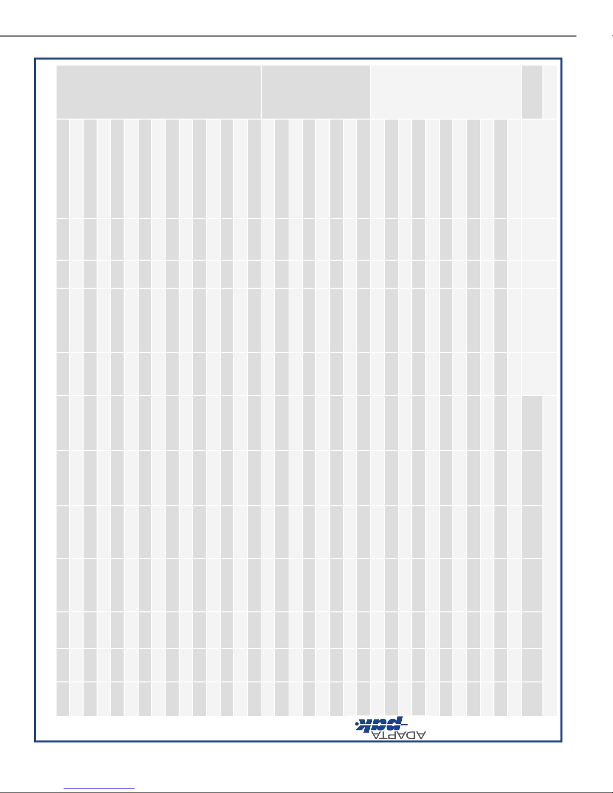
Model Overview
*Not available with split condenser due to single coil design--available with heated and insulated receiver for low ambient applications
^ Uses fixed speed scroll in lieu of digital scroll on low temp due to compressor availability
Model Number
of Fans #
Coils #
Compressors Unit
Weight
Connections
LT Suction
Connection
MT Suction
Connection
LT Liquid
Connection
MT Liquid
Connection
Power
Supply MCA MOPD
Medium
Temp Units
ADP-M0048-L0000* 21 2 2600 1-5/8 1-1/8 208.0 4 7. 3 60.0
ADP-M0079-L0000* 21 2 2600 1-5/8 1-1/8 208.0 60.9 80.0
ADP-M0106-L0000 22 2 2600 1-5/8 1-1/8 208.0 85.7 110.0
ADP-M0152-L0000 22 3 2700 2-1/8 1-1/8 208.0 108.2 125.0
ADP-M0178-L0000 22 3 2700 2-1/8 1-1/8 208.0 134.2 150.0
ADP-M0198-L0000 22 4 2800 2-1/8 1-1/8 208.0 130.7 150.0
ADP-M0253-L0000 32 6 3400 2-1/8 1-1/8 208.0 185.5 200.0
ADP-M0299-L0000 32 6 3500 2-1/8 1-1/8 208.0 208.0 225.0
ADP-M0349-L0000 32 6 3200 3-1/8 1-1/8 208.0 194.0 225.0
ADP-M0403-L0000 42 6 4000 3-1/8 1-1/8 208.0 232.0 250.0
ADP-M0442-L0000 42 6 4000 3-1/8 1-1/8 208.0 240.0 250.0
Low Temp
Units
ADP-M0000-L0032* 21 2 2600 1-5/8 7/8 208.0 62.2 80.0
ADP-M0000-L0052* 21 2 2600 1-5/8 7/8 208.0 81.8 110.0
ADP-M0000-L0076* 21 3 2700 2-1/8 7/8 208.0 105.7 125.0
ADP-M0000-L0099 22 4 2800 2-1/8 7/8 208.0 129.6 150.0
ADP-M0000-L0122 22 5 2950 2-1/8 7/8 208.0 153.5 175.0
ADP-M0000-L0145 22 6 3100 2-1/8 7/8 208.0 17 7. 4 200.0
ADP-M0000-L0161 32 6 3200 3-1/8 7/8 208.0 187.0 200.0
ADP-M0000-L0190 32 6 3250 3-1/8 7/8 208.0 213.0 225.0
Dual Temp
Units
ADP-M0048-L0012*^ 21 4 2800 7/8 1-5/8 1/2 1-1/8 208.0 64.3 80.0
ADP-M0079-L0012*^ 21 4 2800 7/8 1-5/8 1/2 1-1/8 208.0 7 7. 9 100.0
ADP-M0106-L0012^ 22 4 2800 7/8 1-5/8 1/2 1-1/8 208.0 97. 9 125.0
ADP-M0152-L0012^ 22 5 2950 7/8 2-1/8 1/2 1-1/8 208.0 120.2 150.0
ADP-M0178-L0012^ 22 5 2950 7/8 2-1/8 1/2 1-1/8 208.0 146.2 175.0
ADP-M0048-L0032* 21 4 2800 1-5/8 1-5/8 7/8 1-1/8 208.0 86.8 100.0
ADP-M0079-L0032 22 4 2800 1-5/8 1-5/8 7/8 1-1/8 208.0 100.4 110.0
ADP-M0106-L0032 22 4 2800 1-5/8 1-5/8 7/8 1-1/8 208.0 120.2 150.0
ADP-M0152-L0032 22 4 2950 1-5/8 2-1/8 7/8 1-1/8 208.0 142.7 175.0
ADP-M0048-L0052 22 4 2800 1-5/8 1-5/8 7/8 1-1/8 208.0 106.4 125.0
ADP-M0079-L0052 22 4 2800 1-5/8 1-5/8 7/8 1-1/8 208.0 120.0 150.0
ADP-M0106-L0052 22 4 2800 1-5/8 1-5/8 7/8 1-1/8 208.0 139.8 175.0
ADP-M0048-L0076 22 5 2950 2-1/8 1-5/8 7/8 1-1/8 208.0 130.3 150.0
ADP-M0079-L0076 22 5 2950 2-1/8 1-5/8 7/8 1-1/8 208.0 143.9 175.0
ADP-M0106-L0076 22 5 2950 2-1/8 1-5/8 7/81-1/8 208.0 163.7 175.0
TM
Model Overview
*Not available with split condenser due to single coil design--available with heated and insulated receiver for low ambient applications
^ Uses fixed speed scroll in lieu of digital scroll on low temp due to compressor availability
Model Number
of Fans #
Coils #
Compressors Unit
Weight
Connections
LT Suction
Connection
MT Suction
Connection
LT Liquid
Connection
MT Liquid
Connection
Power
Supply MCA MOPD
Medium
Temp Units
ADP-M0048-L0000* 21 2 2600 1-5/8 1-1/8 208.0 47. 3 60.0
ADP-M0079-L0000* 21 2 2600 1-5/8 1-1/8 208.0 60.9 80.0
ADP-M0106-L0000 22 2 2600 1-5/8 1-1/8 208.0 8 5.7 110.0
ADP-M0152-L0000 22 3 2700 2-1/8 1-1/8 208.0 108.2 125.0
ADP-M0178-L0000 22 3 2700 2-1/8 1-1/8 208.0 134.2 150.0
ADP-M0198-L0000 22 4 2800 2-1/8 1-1/8 208.0 130.7 150.0
ADP-M0253-L0000 32 6 3400 2-1/8 1-1/8 208.0 185.5 200.0
ADP-M0299-L0000 32 6 3500 2-1/8 1-1/8 208.0 208.0 225.0
ADP-M0349-L0000 32 6 3200 3-1/8 1-1/8 208.0 194.0 225.0
ADP-M0403-L0000 42 6 4000 3-1/8 1-1/8 208.0 232.0 250.0
ADP-M0442-L0000 42 6 4000 3-1/8 1-1/8 208.0 240.0 250.0
Low Temp
Units
ADP-M0000-L0032* 21 2 2600 1-5/8 7/8 208.0 62.2 80.0
ADP-M0000-L0052* 21 2 2600 1-5/8 7/8 208.0 81.8 110.0
ADP-M0000-L0076* 21 3 2700 2-1/8 7/8 208.0 105.7 125.0
ADP-M0000-L0099 22 4 2800 2-1/8 7/8 208.0 129.6 150.0
ADP-M0000-L0122 22 5 2950 2-1/8 7/8 208.0 153.5 175.0
ADP-M0000-L0145 22 6 3100 2-1/8 7/8 208.0 17 7. 4 200.0
ADP-M0000-L0161 32 6 3200 3 -1/8 7/8 208.0 18 7. 0 200.0
ADP-M0000-L0190 32 6 3250 3-1/8 7/8 208.0 213.0 225.0
Dual Temp
Units
ADP-M0048-L0012*^ 21 4 2800 7/8 1- 5/8 1/2 1-1/8 208.0 64.3 80.0
ADP-M0079-L0012*^ 21 4 2800 7/8 1-5/8 1/2 1-1/8 208.0 7 7. 9 100.0
ADP-M0106-L0012^ 22 4 2800 7/8 1-5/8 1/2 1-1/8 208.0 9 7.9 125.0
ADP-M0152-L0012^ 22 5 2950 7/8 2-1/8 1/2 1-1/8 208.0 120.2 150.0
ADP-M0178-L0012^ 22 5 2950 7/8 2-1/8 1/2 1-1/8 208.0 146.2 175.0
ADP-M0048-L0032* 21 4 2800 1-5/8 1-5/8 7/8 1-1/8 208.0 86.8 100.0
ADP-M0079-L0032 22 4 2800 1- 5/8 1-5/8 7/8 1-1/8 208.0 100.4 110.0
ADP-M0106-L0032 22 4 2800 1-5/8 1-5/8 7/8 1-1/8 208.0 120.2 150.0
ADP-M0152-L0032 22 4 2950 1-5/8 2-1/8 7/8 1-1/8 208.0 142.7 175.0
ADP-M0048-L0052 22 4 2800 1-5/8 1-5/8 7/8 1-1/8 208.0 106.4 125.0
ADP-M0079-L0052 22 4 2800 1-5/8 1-5/8 7/8 1-1/8 208.0 120.0 150.0
ADP-M0106-L0052 22 4 2800 1-5/8 1-5/8 7/8 1-1/8 208.0 139.8 175.0
ADP-M0048-L0076 22 5 2950 2-1/8 1-5/8 7/8 1-1/8 208.0 130.3 150.0
ADP-M0079-L0076 22 5 2950 2-1/8 1-5/8 7/8 1-1/8 208.0 143.9 175.0
ADP-M0106-L0076 22 5 2950 2-1/8 1-5/8 7/81-1/8 208.0 163.7 175.0
15
AdaptaPAK® Parallel Refrigeration System
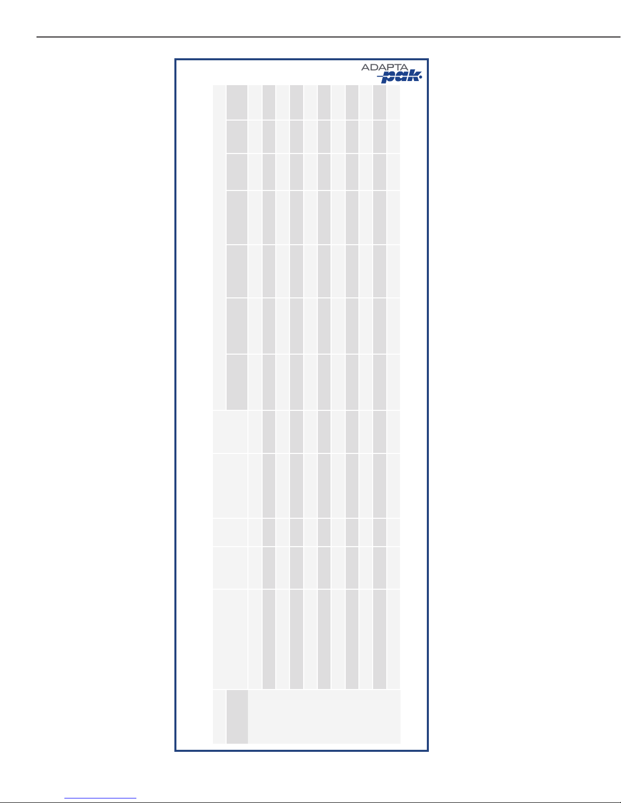
TM
Model Number
of Fans #
Coils #
Compressors Unit
Weight
Connections
LT Suction
Connection
MT Suction
Connection
LT Liquid
Connection
MT Liquid
Connection
Power
Supply MCA MOPD
Dual Temp
Units
Continued
ADP-M0178-L0032 32 5 3400 1-5/8 2-1/8 7/8 1-1/8 208.0 175.6 200.0
ADP-M0152-L0052 32 5 3400 1-5/8 2-1/8 7/8 1-1/8 208.0 169.2 200.0
ADP-M0178-L0052 32 5 3400 1-5/8 2-1/8 7/8 1-1/8 208.0 195.2 225.0
ADP-M0152-L0076 32 6 3500 2-1/8 2-1/8 7/8 1-1/8 208.0 193.1 225.0
ADP-M0178-L0076 32 6 3500 2-1/8 2-1/8 7/8 1-1/8 208.0 219.1 250.0
ADP-M0108-L0090 32 5 3200 2-5/8 2-1/8 7/8 5/8 208.0 169.0 175.0
ADP-M0131-L0095 32 5 3200 2-5/8 2-1/8 7/8 5/8 208.0 182.0 200.0
ADP-M0161-L0095 32 6 3300 2-5/8 2-1/8 7/8 5/8 208.0 196.0 225.0
ADP-M0221-L0052 32 5 3250 2-1/8 2-5/8 5/8 7/8 208.0 184.0 200.0
ADP-M0221-L0062 32 5 3250 2-1/8 2-5/8 5/8 7/8 208.0 193.0 225.0
ADP-M0221-L0095 32 6 3400 2-1/8 2-5/8 7/8 7/8 208.0 223.0 250.0
Model Overview continued...
*Not available with split condenser due to single coil design--available with heated and insulated receiver for low ambient applications
^ Uses fixed speed scroll in lieu of digital scroll on low temp due to compressor availability
TM
Model Overview
*Not available with split condenser due to single coil design--available with heated and insulated receiver for low ambient applications
^ Uses fixed speed scroll in lieu of digital scroll on low temp due to compressor availability
Model Number
of Fans #
Coils #
Compressors Unit
Weight
Connections
LT Suction
Connection
MT Suction
Connection
LT Liquid
Connection
MT Liquid
Connection
Power
Supply MCA MOPD
Medium
Temp Units
ADP-M0048-L0000* 21 2 2600 1-5/8 1-1/8 208.0 4 7. 3 60.0
ADP-M0079-L0000* 21 2 2600 1-5/8 1-1/8 208.0 60.9 80.0
ADP-M0106-L0000 22 2 2600 1-5/8 1-1/8 208.0 85.7 110.0
ADP-M0152-L0000 22 3 2700 2-1/8 1-1/8 208.0 108.2 125.0
ADP-M0178-L0000 22 3 2700 2-1/8 1-1/8 208.0 134.2 150.0
ADP-M0198-L0000 22 4 2800 2-1/8 1-1/8 208.0 130.7 150.0
ADP-M0253-L0000 32 6 3400 2-1/8 1-1/8 208.0 185.5 200.0
ADP-M0299-L0000 32 6 3500 2-1/8 1-1/8 208.0 208.0 225.0
ADP-M0349-L0000 32 6 3200 3-1/8 1-1/8 208.0 194.0 225.0
ADP-M0403-L0000 42 6 4000 3-1/8 1-1/8 208.0 232.0 250.0
ADP-M0442-L0000 42 6 4000 3-1/8 1-1/8 208.0 240.0 250.0
Low Temp
Units
ADP-M0000-L0032* 21 2 2600 1-5/8 7/8 208.0 62.2 80.0
ADP-M0000-L0052* 21 2 2600 1-5/8 7/8 208.0 81.8 110.0
ADP-M0000-L0076* 21 3 2700 2-1/8 7/8 208.0 105.7 125.0
ADP-M0000-L0099 22 4 2800 2-1/8 7/8 208.0 129.6 150.0
ADP-M0000-L0122 22 5 2950 2-1/8 7/8 208.0 153.5 175.0
ADP-M0000-L0145 22 6 3100 2-1/8 7/8 208.0 17 7. 4 200.0
ADP-M0000-L0161 32 6 3200 3-1/8 7/8 208.0 187.0 200.0
ADP-M0000-L0190 32 6 3250 3-1/8 7/8 208.0 213.0 225.0
Dual Temp
Units
ADP-M0048-L0012*^ 21 4 2800 7/8 1-5/8 1/2 1-1/8 208.0 64.3 80.0
ADP-M0079-L0012*^ 21 4 2800 7/8 1-5/8 1/2 1-1/8 208.0 7 7. 9 100.0
ADP-M0106-L0012^ 22 4 2800 7/8 1-5/8 1/2 1-1/8 208.0 97. 9 125.0
ADP-M0152-L0012^ 22 5 2950 7/8 2-1/8 1/2 1-1/8 208.0 120.2 150.0
ADP-M0178-L0012^ 22 5 2950 7/8 2-1/8 1/2 1-1/8 208.0 146.2 175.0
ADP-M0048-L0032* 21 4 2800 1-5/8 1-5/8 7/8 1-1/8 208.0 86.8 100.0
ADP-M0079-L0032 22 4 2800 1-5/8 1-5/8 7/8 1-1/8 208.0 100.4 110.0
ADP-M0106-L0032 22 4 2800 1-5/8 1-5/8 7/8 1-1/8 208.0 120.2 150.0
ADP-M0152-L0032 22 4 2950 1-5/8 2-1/8 7/8 1-1/8 208.0 142.7 175.0
ADP-M0048-L0052 22 4 2800 1-5/8 1-5/8 7/8 1-1/8 208.0 106.4 125.0
ADP-M0079-L0052 22 4 2800 1-5/8 1-5/8 7/8 1-1/8 208.0 120.0 150.0
ADP-M0106-L0052 22 4 2800 1-5/8 1-5/8 7/8 1-1/8 208.0 139.8 175.0
ADP-M0048-L0076 22 5 2950 2-1/8 1-5/8 7/8 1-1/8 208.0 130.3 150.0
ADP-M0079-L0076 22 5 2950 2-1/8 1-5/8 7/8 1-1/8 208.0 143.9 175.0
ADP-M0106-L0076 22 5 2950 2-1/8 1-5/8 7/81-1/8 208.0 163.7 175.0
TM
Model Overview
*Not available with split condenser due to single coil design- -available with heated and insulated receiver for low ambient applications
^ Uses fixed speed scroll in lieu of digital scroll on low temp due to compressor availability
Model Number
of Fans #
Coils #
Compressors Unit
Weight
Connections
LT Suction
Connection
MT Suction
Connection
LT Liquid
Connection
MT Liquid
Connection
Power
Supply MCA MOPD
Medium
Temp Units
ADP-M0048-L0000* 21 2 2600 1-5/8 1-1/8 208.0 4 7. 3 60.0
ADP-M0079-L0000* 21 2 2600 1-5/8 1-1/8 208.0 60.9 80.0
ADP-M0106-L0000 22 2 2600 1-5/8 1-1/8 208.0 85.7 110.0
ADP-M0152-L0000 22 3 2700 2-1/8 1-1/8 208.0 108.2 125.0
ADP-M0178-L0000 22 3 2700 2-1/8 1-1/8 208.0 134.2 150.0
ADP-M0198-L0000 22 4 2800 2-1/8 1-1/8 208.0 130.7 150.0
ADP-M0253-L0000 32 6 3400 2-1/8 1-1/8 208.0 185.5 200.0
ADP-M0299-L0000 32 6 3500 2-1/8 1-1/8 208.0 208.0 225.0
ADP-M0349-L0000 32 6 3200 3-1/8 1-1/8 208.0 194.0 225.0
ADP-M0403-L0000 42 6 4000 3-1/8 1-1/8 208.0 232.0 250.0
ADP-M0442-L0000 42 6 4000 3-1/8 1-1/8 208.0 240.0 250.0
Low Temp
Units
ADP-M0000-L0032* 21 2 2600 1-5/8 7/ 8 208.0 62.2 80.0
ADP-M0000-L0052* 21 2 2600 1-5/8 7/8 208.0 81.8 110.0
ADP-M0000-L0076* 21 3 2700 2-1/8 7/8 208.0 105.7 125.0
ADP-M0000-L0099 22 4 2800 2-1/8 7/8 208.0 129.6 150.0
ADP-M0000-L0122 22 5 2950 2-1/8 7/8 208.0 153.5 175.0
ADP-M0000-L0145 22 6 3100 2-1/8 7/8 208.0 177.4 200.0
ADP-M0000-L0161 32 6 3200 3 -1/8 7/8 208.0 1 8 7. 0 200.0
ADP-M0000-L0190 32 6 3250 3-1/8 7/8 208.0 213.0 225.0
Dual Temp
Units
ADP-M0048-L0012*^ 21 4 2800 7/8 1-5/8 1/2 1-1/8 208.0 64.3 80.0
ADP-M0079-L0012*^ 21 4 2800 7/8 1-5/8 1/2 1-1/8 208.0 7 7. 9 100.0
ADP-M0106-L0012^ 22 4 2800 7/8 1-5/8 1/2 1-1/8 208.0 97. 9 125.0
ADP-M0152-L0012^ 22 5 2950 7/8 2-1/8 1/2 1-1/8 208.0 120.2 150.0
ADP-M0178-L0012^ 22 5 2950 7/8 2-1/8 1/2 1-1/8 208.0 146.2 175.0
ADP-M0048-L0032* 21 4 2800 1- 5/8 1-5/8 7/8 1-1/8 208.0 86.8 100.0
ADP-M0079-L0032 22 4 2800 1-5/8 1- 5/8 7/8 1-1/8 208.0 100.4 110.0
ADP-M0106-L0032 22 4 2800 1-5/8 1-5/8 7/8 1-1/8 208.0 120.2 150.0
ADP-M0152-L0032 22 4 2950 1- 5/8 2-1/8 7/ 8 1-1/8 208.0 142.7 175.0
ADP-M0048-L0052 22 4 2800 1-5/8 1-5/8 7/8 1-1/8 208.0 106.4 125.0
ADP-M0079-L0052 22 4 2800 1-5/8 1-5/8 7/8 1-1/8 208.0 120.0 150.0
ADP-M0106-L0052 22 4 2800 1-5/8 1-5/8 7/ 8 1-1/8 208.0 139.8 175.0
ADP-M0048-L0076 22 5 2950 2-1/8 1-5/8 7/ 8 1-1/8 208.0 130.3 150.0
ADP-M0079-L0076 22 5 2950 2-1/8 1-5/8 7/8 1-1/8 208.0 143.9 175.0
ADP-M0106-L0076 22 5 2950 2-1/8 1-5/8 7/81-1/8 208.0 163.7 175.0

16 AdaptaPAK® Parallel Refrigeration System
Key to Codes in AdaptaPAK Model Numbers
ADP-MXXXX-LXXXX- ______
ADP = AdapatPAK Platform
(X) - Number of Condenser Fans
MXXXX = Medium Temperature Load in KBTUs
LXXXX = Low Temperature Load in KBTUs
SUFFIX - KEY TO OPTIONS
SPLIT
CONDENSER
EC
MOTOR
COATED
COIL
HAIL
GUARD
HEAT
RECLAIM
LP
SWITCH/COMPR
S E C H R P
Example: ADP-M0079-L0012-ER
ADAPTAPAK Model Breakdown
(the number in parentheses is the number of condenser fans)
LOW TEMP
SINGLE SUCTION
MED TEMP
SINGLE SUCTION
MEDIUM TEMP AND LOW TEMP
DUAL SUCTION
ADP(2)-M0000-L0032 ADP(2)-M0048-L0000 ADP(2)-M0048-L0012 ADP(3)-M0178-L0032
ADP(2)-M0000-L0052 ADP(2)-M0079-L0000 ADP(2)-M0079-L0012 ADP(3)-M0152-L0052
ADP(2)-M0000-L0076 ADP(2)-M0106-L0000 ADP(2)-M0106-L0012 ADP(3)-M0178-L0052
ADP(2)-M0000-L0099 ADP(2)-M0152-L0000 ADP(2)-M0152-L0012 ADP(3)-M0152-L0076
ADP(2)-M0000-L0122 ADP(2)-M0178-L0000 ADP(2)-M0178-L0012 ADP(3)-M0178-L0076
ADP(2)-M0000-L0145 ADP(2)-M0198-L0000 ADP(2)-M0048-L0032 ADP(4)-M0221-L0052
ADP(4)-M0000-L0161 ADP(3)-M0253-L0000 ADP(2)-M0079-L0032 ADP(4)-M0221-L0062
ADP(4)-M0000-L0190 ADP(3)-M0299-L0000 ADP(2)-M0106-L0032 ADP(4)-M0221-L0095
ADP(4)-M0349-L0000 ADP(2)-M0152-L0032
ADP(4)-M0403-L0000 ADP(2)-M0048-L0052
ADP(4)-M0442-L0000 ADP(2)-M0079-L0052
ADP(2)-M0106-L0052
ADP(2)-M0048-L0076
ADP(2)-M0079-L0076
ADP(2)-M0106-L0076
ADP(4)-M0108-L0090
ADP(4)-M0131-L0095
ADP(4)-M0161-L0095

17
AdaptaPAK® Parallel Refrigeration System
Section 2:
DX Refrigeration Systems
Direct expansion (DX) refrigeration is one of the most common methods
used for the removal of heat. Such a system takes heat from a place where
it is unwanted and removes it to a place where it is unobjectionable. The
Hillphoenix® AdaptaPAK® units utilize DX refrigeration to remove heat from
store display cases and walk-in coolers/freezers, and transfer it to an outdoor location where it can be rejected.
Refrigeration Through Vapor Compression
Refrigeration is accomplished through application of various mechanical principles that occur as part of a
continuous cycle, commonly known as the Vapor Compression Refrigeration Cycle.
In the vapor compression cycle, heat is absorbed as the liquid refrigerant in the evaporator changes to a vapor. The
refrigerant boils at the new saturation point in the evaporator (located in the display case or cooler) where it changes
to a superheated vapor. From the evaporator, the superheated refrigerant vapor enters the compressor and the
refrigerant is compressed and changed from a low pressure superheated vapor to a high pressure superheated
vapor (more on this later), It then ows to the condenser. In a simple refrigeration system, the ambient air outside of
the condenser ows through the coils of the condenser where it absorbs heat from the vapor refrigerant causing it to
change back to its liquid state before moving through the metering device where it crosses from the high pressure
side of the system to the low pressure side. On the low pressure side, the refrigerant returns to the evaporator and
the process (refrigeration cycle) is then repeated.
Refrigeration System Components
Knowing how the refrigeration process works helps in understanding where in the sequence of operation the major
components of the mechanical system are, and the functions they perform. Almost any refrigeration system is built
around four main components.
The four main components are:
• Compressor
• Condenser
• Metering Device (also known as an expansion valve)
• Evaporator
Beginning on the next page, these main components are individually presented and discussed.

18 AdaptaPAK® Parallel Refrigeration System
Compressor
The compressor in a mechanical, vapor compression refrigeration system performs a basic function. It generates the
pressure differential to move the refrigerant through the complete refrigeration cycle. It accomplishes its function in
several simple steps. These steps are:
• The compressor draws in the low pressure refrigerant vapor from the evaporator (compressor suction side).
• Through mechanical means, the compressor compresses the refrigerant vapor to a high pressure.
• The high pressure refrigerant vapor is forced to exit the compressor through a discharge line.
The compressor performs work on the refrigerant by compressing it and raising its pressure and temperature. It thus
adds energy to the refrigerant vapor.
Different types of compressors are used in different systems for various reasons. Some, called reciprocating
compressors, draw the refrigerant into a cylinder, compress it, and then discharge it at a higher pressure. Other types
compress the vapor between mating pairs of off-center scrolls (scroll compressors). Regardless of the method used, all
types of compressors are designed to compress the refrigerant vapor, and thereby increase its pressure and move it
through the refrigeration system.
Condenser
The condenser in a refrigeration system is designed to reject the heat energy that was picked up in the evaporator
and the compressor, and reject it to the cooler outside ambient air. This process causes the high pressure
refrigerant vapor to condense and become a high pressure liquid. The condenser operates as follows:
• The high pressure/temperature refrigerant vapor enters the condenser via the compressor discharge line.
• As the hot vapor enters the condenser and begins to ow through tubes of the condenser coil, lower temperature
ambient air is drawn across the outside of the condenser’s tubes/ns. An operating fan is often used as the
motive force to move the air through the condenser coil.
• Due to the temperature difference, heat is transferred from the hot refrigerant to the cooler ambient air.
• As the hot refrigerant vapor gives up its heat, it changes state (condenses) and becomes a liquid.
• This liquid refrigerant then leaves the condenser via the “liquid line,” and travels to the metering device.
All refrigeration systems utilize a condenser, with one of the most common types being air-cooled. The tubes of the
condenser have copper or aluminum ns attached to them which act to dissipate the heat more effectively (other
materials are used, but copper and aluminum are the most common).
Pressure is controlled in the condenser by a variety of means. On air-cooled condensers, a valve in the condenser’s
return line closes at a preset pressure in order to maintain pressure in the coil. As the pressure increases, the valve
modulates so that a consistent pressure is maintained. The fans that force ambient air through the condenser are
also cycled on and off to assist in the heat transfer process as needed.

19
AdaptaPAK® Parallel Refrigeration System
Metering Device (Expansion Valve)
After the condenser, the high pressure liquid refrigerant reaches the metering device (expansion valve). The metering
device meters, or controls, the ow of refrigerant from the high pressure, high temperature side of the system to the
low pressure, low temperature evaporator. Important functions include:
• The metering device (expansion valve) regulates how much liquid refrigerant ows and enters the evaporator.
• The small opening for liquid refrigerant ow takes different forms. In some systems the metering device is a
small thin copper tube known as a capillary tube; in others it is a small orice that regulates ow; and in other
refrigeration systems it is a thermostatic expansion valve (TEV or TXV).
• Control of the size of the opening for ow is crucial. It determines how much liquid refrigerant is allowed to
pass. The size of this opening determines the temperature difference that exists between the saturated suction
temperature (SST) and the temperature at the outlet of the evaporator. This temperature difference is so
important that it has its own specic name—superheat.
One of the most common types of metering device is the thermostatic expansion valve (often referred to as a
TXV or TEV). The opening/closing of these valves is controlled by the pressure and temperature at the exit of the
evaporator.
Evaporator
Liquid refrigerant enters the evaporator from the metering device. The evaporator is located in the space that is being
refrigerated. Several things happen in the evaporator:
• The liquid refrigerant entering the evaporator from the metering device (expansion valve) undergoes an
instantaneous large pressure decrease (per the P-T chart, this is also a large temperature decrease).
• As it enters the evaporator, the liquid refrigerant immediately begins to absorb heat from the warm air owing
over the tubes and ns of the evaporator coil.
• With the absorption of heat, the liquid refrigerant also begins to change state (boil) to become a vapor.
• As the refrigerant continues to ow through the tubes of the evaporator, the continued absorption of heat results
in more and more of the liquid refrigerant changing state to become a vapor.
• Prior to its exit from the evaporator, the refrigerant will have completely changed over to the superheated vapor
state, and will then enter the suction line and head back to the compressor.
Inside the evaporator is where the refrigerant absorbs heat to carry it away from the refrigerated space. This could be
the refrigerated space of a display case, a reach-in cooler. or walk-in freezer in which frozen foods are kept.
The basic principle at work here is that heat always moves from areas of higher temperature to areas of lower
temperature. The refrigerant absorbs heat in the evaporator because it is at a lower temperature than the air moving
across the evaporator. This temperature difference (TD) between the refrigerant and the air is approximately 8 to 10 °F.
Other components of refrigeration systems besides these basic ones are mainly just combinations of accessories
and options that expand the capabilities of the system. Several of these are discussed later in this manual.

20 AdaptaPAK® Parallel Refrigeration System
This manual suits for next models
44
Table of contents
Other Hillphoenix Refrigerator manuals


Popular Refrigerator manuals by other brands

Grundig
Grundig GKN 26860 XPHN Instructions for use

CORBERO
CORBERO FE 850 S/2 operating instructions

Sharp
Sharp SJ-NBA22DHXWE-EU user manual

Urban Islands
Urban Islands 21008 Installation & operating instructions

KitchenAid
KitchenAid DHT-486XP installation instructions

Whirlpool
Whirlpool GB2FHDXWQ00 parts list

Electrolux
Electrolux ER2640C instructions

Miele
Miele KF 7654 SNE ed OPERATING AND INSTALLATION Manual

Signature Kitchen Suite
Signature Kitchen Suite SKSUD2402P owner's manual

Hisense
Hisense RB372N4ADE User's operation manual

SEVERIN
SEVERIN KS9783 Instructions for use

Frigidaire
Frigidaire FTE5200SBRE operating instructions


