Hiltron XM22 User manual

XM22
XM22PX
1
XM22 - Consolle XM
!Display alfanumerico LCD retroilluminato (2x16 caratteri)
!Tamper di protezione antiapertura ed antistrappo
!Colore bianco
!Ingressi programmabili 1
!Lettore per chiave di prossimità integrato (XM22PX)
!Buzzer
!Tensione nominale di alimentazione 12Vcc ±5%
!Assorbimento normale 120mA
!LED di segnalazione
!Grado protezione del contenitore IP40
!Uscita logica a collettore aperto 30mAmax. 1
!Contenitore esternoABS
!Grado di sicurezza 1
!Classe ambientale 2
!Dimensioni (LxAxP) 107x141x25mm
!Conforme norme CEI EN 50131-1
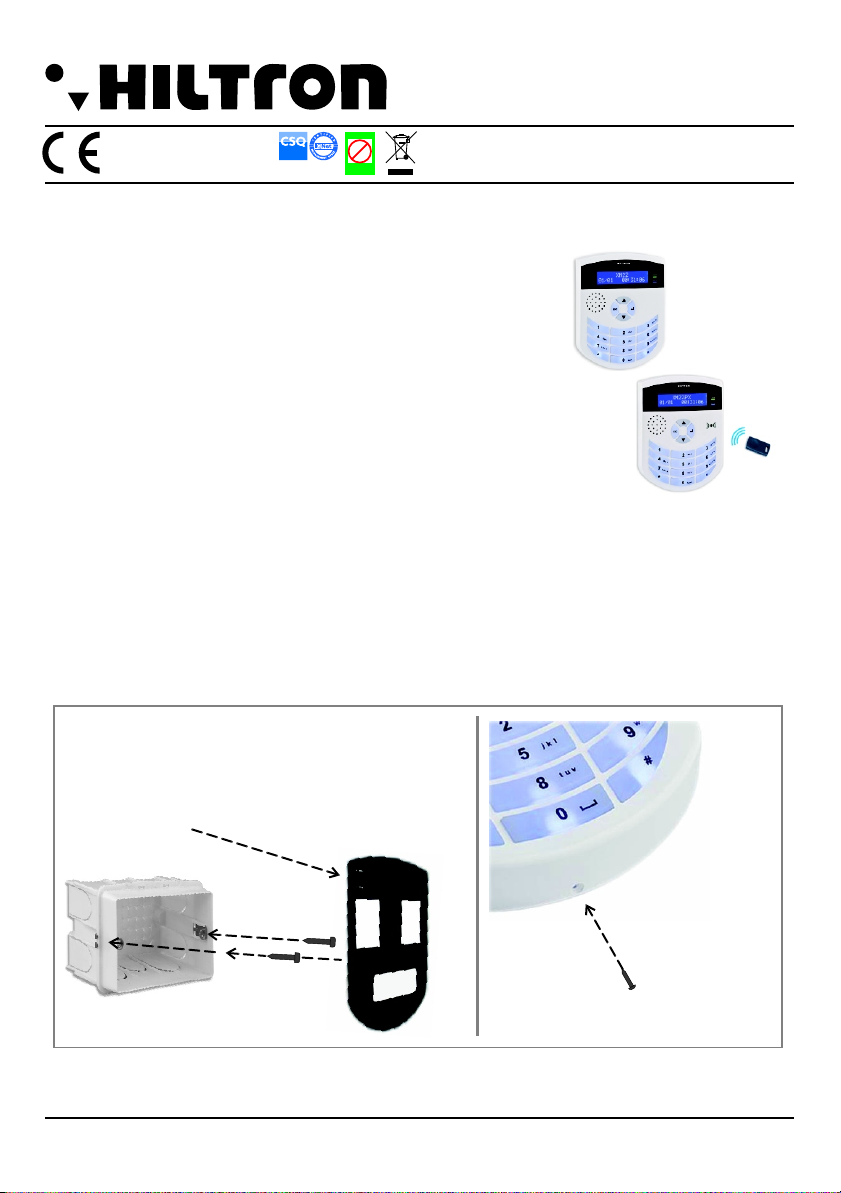
Installazione
!Non installare la consolle in luoghi esposti a temperature estreme o alle intemperie.
!Fissare la consolle ad un'altezza che permetta un agevole accesso al pannello frontale.
!Per un fissaggio solido ed affidabile, è indispensabile assicurarsi che la superfice di appoggio sia piana.
Le consolle sono protette contro le manomissioni, ciò nonostante l‘installazione in un locale protetto
ed eventualmente nella zona di copertura di un rivelatore volumetrico è una protezione supplementare.
NOTA:
Serrare la vite come in figura per
fissare il coperchio con la base
Il fondo della consolle può essere montato
su una comune cassetta murale tipo “503”.
Per la protezione antistrappo,fissare
con la vite in dotazione
XM22PX - Consolle XM con lettore XMK
EMC/2006/95/CE
MADE IN ITALY
Pb
Lead free
RoHS
compliant
Pb
Lead free
RoHS
compliant
Pb
Lead free
RoHS
compliant
Pb
Lead free
RoHS
compliant
RAEE
Azienda con Sistema di
gestione per la Qualità
UNI EN ISO 9001:2000
2
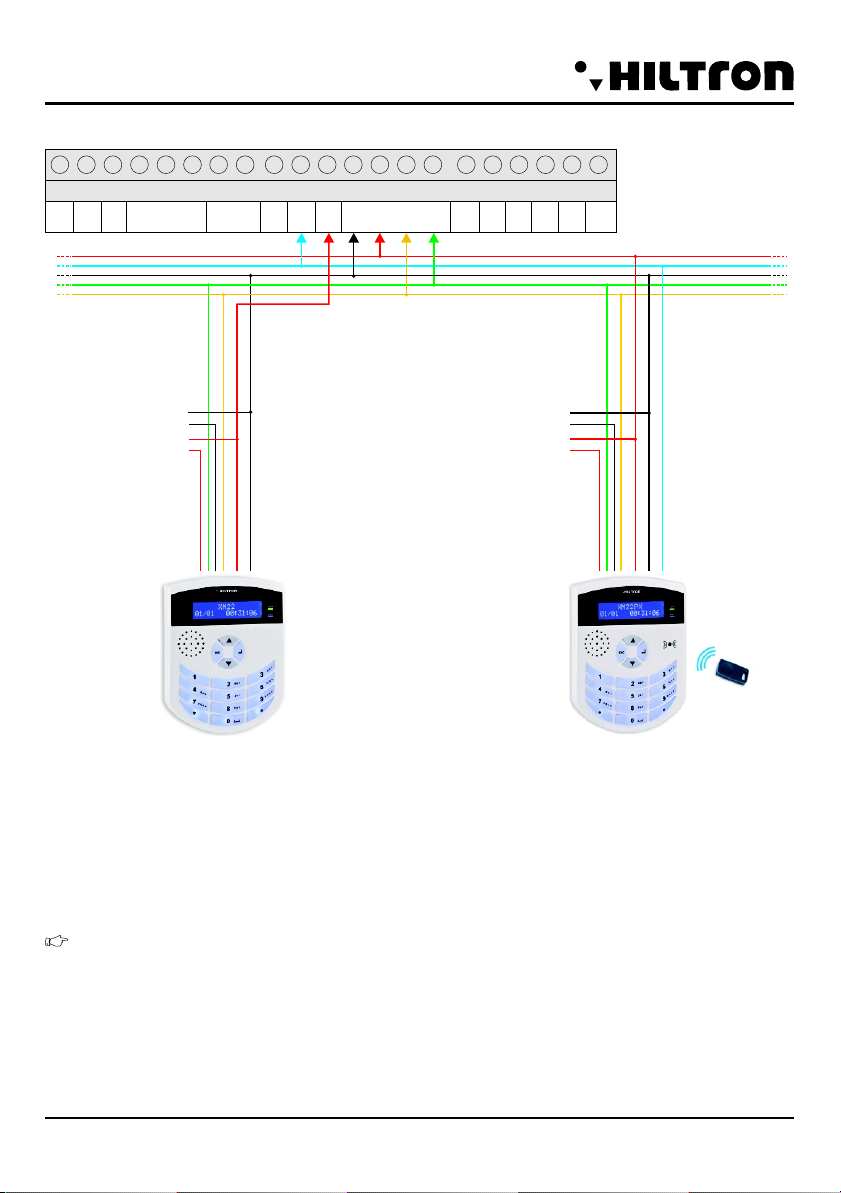
Cablaggio Consolle (Tipo 04)
Ogni consolle è dotata di:
&Un ingresso (con riferimento al negativo 12V) programmabile come indicato nella tabella
“PARAMETRI” che si aggiunge a quelli presenti in centrale.
&Un'uscita a collettore aperto (con riferimento al positivo 12V)programmabile.
NOTA: Il positivo '+' ed il negativo '-' presenti sulla morsettiera 'Consolle' della centrale sono
elettricamente gli stessi '+ EXT e 'GND' che alimentano la linea multiplexer.
IN
OUT
GND +12 +In +SA COM + SIR + OUT
011
010
AUX
GND MPX -+A B
Consolle
IN GND IN IN GND IN
009 010 011 012
009 EXT
CENTRALE SERIE XM
Nero / : GND
Blu / : MPX
Rosso / : +12V EXT
Giallo / : Linea consolle RS485A
Verde / : Linea consolle RS485B
rosso
verde
giallo
nero
IN
OUT
Lettore di chiave XM22PX (Tipo 08)
Ogni consolle XM22 e XM22B è dotata di un lettore di chiave di prossimità:
&Per usarlo è necessario collegare anche il cavo blu sulla linea Multiplexer.
&Per riconoscere e programmare la chiave di prossimità fare riferimento al paragrafo 6.5
Programmazione Zone del manuale “INSTALLAZIONE E SETUP” SerieXM
rosso
verde
giallo
nero
blu
XM22 XM22PX
XM22 - XM22PX - Consolle con display alfanumerico Serie XM

Programmazione consolle
Per cambiare la lingua della consolle:
!quando si da corrente la prima volta,utilizzare i tasti e per scegliere la lingua indicata sul
display
!premere per confermare
Per visualizzare e/o modificare la lingua scelta togliere e poi dare corrente alla consolle, poi premere 4
volte ; entro 30 secondi
NOTA: Se la consolle non risulta connessa alla linea multiplexer il cambio della lingua è sempre
possibile, digitando 4 volte il tasto
Configurazione ID
Di serie ogni consolle ha l'ID impostato a “01”. Per installare più consolle sulla linea multiplexer è
necessario assegnare ID differenti (fino a 8 ID).
Per cambiare l'ID della consolle:
!dare corrente alla consolle
!premere 4 volte entro 30 secondi; viene visualizzato l’ID corrente
!utilizzare i tasti e per scegliere l'ID
!premere per confermare
NOTA: Se la consolle non risulta connessa alla linea dati (AB) il cambio dell'ID è sempre
possibile.
NOTA: se si collegano il positivo '+' ed il negativo '-' della consolle su una batteria è possibile leggere la
tensione di quest'ultima. Una volta collegata la consolle alla linea multiplexer, l'informazione acquisita
viene inviata alla centrale per poter essere letta anche dalle altre consolle.
Funzionamento LED
Sulle consolle XM22 e XM22PX i due LED indicano normalmente lo stato dell’inseritore presente al suo
interno. Se si preme un tasto qualunque i due LED indicano, invece, lo stato della consolle per 5 secondi.
NOTA :Se si installa la consolle XM22PX su centrali che gestiscono più di un solo impianto, i LED
segnaleranno lo stato dell’inseritore. E’ quindi consigliabile associare sia la consolle, che il lettore
integrato allo stesso impianto.
Retroilluminazione Display
Digitando il pulsante per circa 3 secondi, si spengono contemporaneamente:
le retroilluminazioni del display; della tastiera e del logo.
Digitando invece il pulsante si spengono anche i LED di segnalazione dello stato dell’impianto.
Per riattivare il normale funzionamento bisogna premere il pulsante per circa 3 secondi.
Con la consolle spenta, agendo su un qualsiasi pulsante la retroilluminazione si riattiva per circa 20
secondi consentendo l’utilizzo della stessa.
Si riattiva sempre per circa 20 secondi in caso di ALLARME o di GONG apertura zone o
SEGNALAZIONE ERRORE ALIMENTAZIONE.
Disabilitazione 24h
In caso di disabilitazione della 24h, il lampeggio si verifica solo sulla consolle di indirizzo “1”.
XM22 - XM22PX - Consolle con display alfanumerico Serie XM
3
9
1
7
0
0
4
XM22 - XM22PX - Consolle con display alfanumerico Serie XM
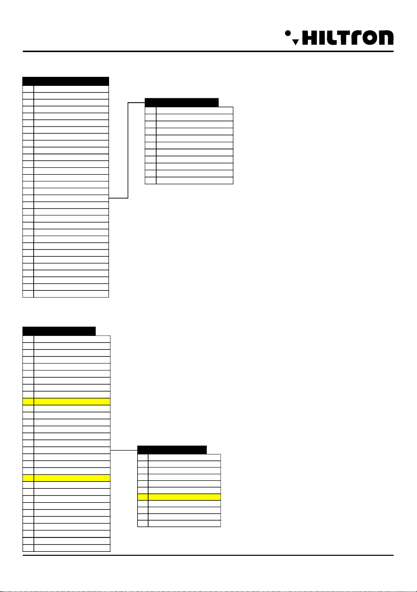
Tabella lettore chiave (XM22PX Tipo 08)
La seguente tabella illustra quali sono le funzionalità principali del Tipo08
DISINSERIMENTO01
FUNZIONE
INSERIMENTO02
INSER. / DISINSER.03
INSERIM. SILENZIOSO04
INSER. SIL. / DISINS.05
STOP ANTIRAPINA06
STOP ALLARME07
ZONA IMMEDIATA08
ZONA RITARDATA09
24H10
NESSUNA00
ABILITAZIONE01
PARAMETRI
DESCRIZIONE02
SERIALE03
STATO MPX04
ERRORE LINK MPX05
TAMPER / INPUT 24H06
POLAR. NA/NC07
TIPO LOG/BIL08
MANOM. LINEA09
UNUSED10
SENSIBILITA’ DA 1 A 811
NUM. IMPULSI DA 1 A 412
FUNZIONAM. LED
13
IMPIANTO
14
AREA
15
FUNZIONE
16
IMPIANTO COMANDO
17
MODO COMANDO
18
ANTIRAPINA
19
GONG IMM.
21
GONG RIT
22
NUM. IMPULSI DA 1 A 8
23
LIVELLO COMANDO20
USCITA SU BAD MPX27
LED28
START IMPULSO (ST/EV)26
USCITA LOGICA29
INVERS. COMANDO24
TIPO USCITA25
ECHO USCITA
31
MESS. COMUN. DIGIT.
30
Tabella consolle XM22/XM22PX (Tipo 04)
La seguente tabella illustra quali sono le funzionalità principali del Tipo04
ABILITAZIONE01
PARAMETRI
DESCRIZIONE02
SERIALE03
STATO MPX04
ERRORE LINK MPX05
TAMPER / INPUT 24H06
POLAR. NA/NC07
TIPO LOG/BIL08
MANOM. LINEA09
10
SENSIBILITA’ DA 1 A 811
NUM. IMPULSI DA 1 A 412
FUNZIONAM. LED
13
IMPIANTO
14
AREA
15
FUNZIONE
16
IMPIANTO COMANDO
17
MODO COMANDO
18
19
GONG IMM.
21
GONG RIT
22
NUM. IMPULSI DA 1 A 8
23
LIVELLO COMANDO20
USCITA SU BAD MPX27
TIMER IMPULSO (ST/EV)26
LED28
USCITA LOGICA29
USCITA INVERSA24
TIPO USCITA25
MESS.COMUN.DIGIT.30
ECHO USCITA31
Funzioni programmbili
per l’uscita
DISINSERIMENTO01
FUNZIONE
INSERIMENTO02
INSER. / DISINSER.03
INSERIM. SILENZIOSO04
INSER. SIL. / DISINS.05
STOP ANTIRAPINA06
STOP ALLARME07
ZONA IMMEDIATA08
ZONA RITARDATA09
24H10
NESSUNA00
XM22
XM22PX
1
Azienda con Sistema di
gestione per la Qualità
UNI EN ISO 9001:2000
XM22 - Consolle for centrals XM Series
!Alphanumeric backlit display LCD (2x16 characters)
!Antiopening and antitearing protection tamper
!Color white
!Programmable inputs 1
!Reader for proximity key integrated (XM22PX)
!Buzzer
!Power supply voltage 12Vdc ±5%
!Normal current consumption 120mA
!Signalling LED
!Box protection level IP40
!Logical Output open collector + 30mAmax 1
!External boxABS
!Safety degree 1
!Ambiental class 2
!Dimensions (WxHxD) 107x141x25mm
!Approved directives CEI EN 50131-1
Installation
!Do not install the console in places exposed to extremes of temperature or weather.
!Secure the console at a height that allows easy access to the front panel.
!For a solid and reliable, it is necessary to make sure the bearing surface is flat.
The console is protected against tampering, nevertheless the local installation protected and
eventually in the coverage area of a volumetric detector is additional protection.
NOTE:
Tighten the screw as shown in the figure
for secure the lid with the base
The bottom of the console can be mounted
on a common wall box type "503".
For the antitheft protection, fixing
with the screw in dotation.
XM22PX - Consolle for centrals XM Series with reader XMK
Pb
Lead free
RoHS
compliant
RAEE
EMC/2006/95/CE
MADE IN ITALY
2
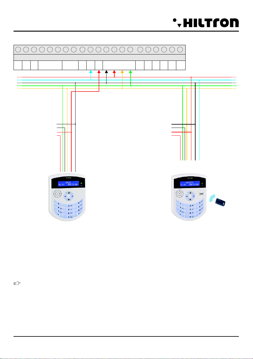
Consolle cable (Type 04)
Each console is equipped with::
&One input (with referring to the negative 12V) programmable as indicated in the table "PARAMETERS"
in addition to those found in central unit.
&Un'uscita a collettore aperto (con riferimento al positivo 12V)programmabile.
NOTE: The plus ' + ' and the negative '-' present on the terminal ' Console ' of the plant are
electrically the same ' + EXT and ' GND ' which feed the line multiplexer.
IN
OUT
GND +12 +In +SA COM + SIR + OUT
011
010
AUX
GND MPX -+A B
Consolle
IN GND IN IN GND IN
009 010 011 012
009 EXT
SERIE XM CENTRAL UNIT
Black / : GND
Blue / : MPX
Red / : +12V EXT
Yellow / : Consolle Line RS485A
Green / : Consolle Line RS485B
red
green
yellow
black
IN
OUT
XM22PX Key reader (Type 08)
Each console XM22 and XM22B is equipped with a proximity key player:
&To use it you must also connect the blue wire on the Multiplexer.
&To recognize and program proximity key reference in paragraph 6.5 Programming Areas of the
manual "installation and SETUP" SerieXM
XM22
red
green
yellow
black
blue
XM22 - XM22PX - Consolle with alphanumeric display Serie XM
XM22PX
Consolle programmation
To change the language of the console:
!when you by running the first time, use the keys choose the language indicated on the
display
!press for confirm
To view and/or change the language you choose Remove and then give power to the console, then press
4 times ; within 30 seconds
NOTE: If the console is not connected to the multiplexer line, the language change is always possible,
typing 4 times
ID configuration
Each serial console has the ID set to "01". To install multiple consoles on line multiplexer, you must assign
different ID (up to 8 ID).
For change the ID of the console:
!give the current console
!press 4 times within 30 seconds; Display visualize the current ID
!utilize the button i tasti and to choose the ID
!press the button for confirm
NOTE: If the console is not connected to the data line (AB) the return ID is always possible.
NOTE: If you connect the positive + and negative '-' of the console on a battery you can read the tension.
Once connected the console to the multiplexer, the information is sent to the control unit to be read even
from other consoles.
LED operation
On the console XM22 and XM22PX the two LEDs indicate the status of the connector normally present
within it. If you press any button the two LEDs indicate the status of the console for 5 seconds.
NOTE :If you install the console XM22PX on central unit that handle more than one system, the
LEDs will report the status of the connector. It is therefore advisable to associate both consoles, that the
reader is integrated at the same plant.
Backlit display
Pressing the button for about 3 seconds, turn OFF at the same time:
the display backlights of the keyboard and logo.
Press the button turn OFF the LED signal the condition of the system.
To resume normal operation you have to press the button for about 3 seconds.
With the console OFF, press any backlight button wakes up for about 20 seconds, allowing the use of the
same.
Always wakes up for about 20 seconds in case of alarm or GONG opening areas or POWER ERROR
SIGNALLING.
24h Disabled
In case of disabling of the 24h zone, the flashing occurs only on the console of the address "1".
3
9
1
7
0
XM22 - XM22PX - Consolle with alphanumeric display Serie XM
0

4
Reader lector table (XM22PX Type 08)
The following table shows what are the major features of the Type08
672ADIE-2.00
XM22/XM22PX Console table (Typo 04)
The following table shows what are the major features of the Type04
XM22 - XM22PX - Consolle with alphanumeric display Serie XM
ENABLING01
PARAMETERS
DESCRIPTION02
SERIAL03
MPX STATUS04
MPX LINK ALARM05
TAMPER06
07
BALANCED LOGIC08
BANCED LINE09
10
SENSITIVTY11
NUMBER OF IR PULSES.12
LED FUNCTION
13
SYSTEM
14
AREA
15
FUNCTION
16
SYSTEM COMMAND
17
COMMAND MODE
18
19
INSTANT GONG
21
DELAYED GONG
22
NUMBER OF PULSES
23
COMMAND LEVEL20
BAD MPX OUTPUT27
LED28
PULSE START26
LOGICAL OUTPUT29
INVERSION COMMAND24
OUTPUT TYPE25
NA\NC POLARITY
/
INPUT 24h
.
01
FUNCTION
02
03
04
05
07
08
09
10
00
DISCONNECTION
CONNECTION
CONN./DISCONN.
SILENT CONNECTION
SIL. CONN./DISCONN.
ALARM STOP
IMMEDIATE ZONE
DELAYED ZONE
24
NONE
H
06 ANTI-THEFT STOP
10 SENS. AND-OR
21 AND-OR SENSITIVITY
COMM. MESS. DIGIT.30
ECHO OUTPUT31
01
FUNCTION
02
03
04
05
07
08
09
10
00
DISCONNECTION
CONNECTION
CONN./DISCONN.
SILENT CONNECTION
SIL. CONN./DISCONN.
ALARM STOP
IMMEDIATE ZONE
DELAYED ZONE
24
NONE
H
06 ANTI-THEFT STOP
ENABLING01
PARAMETERS
DESCRIPTION02
SERIAL03
MPX STATUS04
MPX LINK ALARM05
TAMPER06
07
BALANCED LOGIC08
BANCED LINE09
SENSITIVTY11
NUMBER OF IR PULSES.12
LED FUNCTION
13
SYSTEM
14
AREA
15
FUNCTION
16
SYSTEM COMMAND
17
COMMAND MODE
18
19
INSTANT GONG
21
DELAYED GONG
22
NUMBER OF PULSES
23
COMMAND LEVEL20
BAD MPX OUTPUT27
LED28
PULSE START26
LOGICAL OUTPUT29
INVERSION COMMAND24
OUTPUT TYPE25
NA\NC POLARITY
/
INPUT 24h
.
AND-OR SENSITIVITY
COMM. MESS. DIGIT.30
ECHO OUTPUT31
10 SENS. AND-OR
This manual suits for next models
1
Table of contents
Languages:


