Anilam 5000M User manual

5000M Crusader G Upgrade Installation Guide
P/N 70000549B
All rights reserved. Subject to change without notice. 1
14-February-03
Hardware List
The 5000M Upgrade system has been custom configured to provide the
necessary hardware required for installation on your machine. Verify that
you have received all the correct parts, and then follow the instructions to
ensure a proper installation.
Caution: Do not turn on the system until instructed to do so.
Follow the procedures as outlined.
Be sure to read through all the instructions first before beginning
the actual installation.
The system comes with the following parts:
1. One 5000M Console to match your existing Crusader G
A7533006 – 3-Axis Level 1
A7553002 – 5-Axis Level 2
2. Software Package:
A4530016 – 3-Axis Software Package, or
A4550015 – 5-Axis Software Package
33000205 – M-Function option key (Level 1 or Level 2)
85300009 – Filter kit
3. One console mounting kit selected for your machine:
33000919 – Eye Bolt Bottom Mount, or
32500334 – Standard Ram Arm Mount.
2. Cables
33001094 – Servo interconnect cable
36000271 – AC cable
36000383 – W-axis interconnect cable
36000383 – V-axis interconnect cable
3. Interface Assembly
33001097 – Level 1 interface, or
33001098 – Level 2 interface
4. Any of the following options, if ordered:
33000140 – Spindle Control Option
33000951 – Networking Option
33000907 – Handy Pulser with Emergency Stop Switch
33000122 – Remote Start and Stop Switch

5000M Crusader G Upgrade Installation Guide
P/N 70000549B
All rights reserved. Subject to change without notice. 2
14-February-03
Highlights of the Upgrade
The 5000M upgrade console has a user configurable Setup Utility to
match the system parameters to those of the Crusader G. The default
parameters have been set to most closely match a basic Crusader G
system. Changes may need to be made if your CR G system was
configured differently. See “Section 10” in the Installation Instructions
and refer to the 5000M CNC Setup Utility Manual, P/N 70000509.
The most critical defaults are as follows:
•Rapid Speed is set at 200 IPM.
•Resolution is set for Glass Scales (Linear Encoders) 0.01mm
(0.0005”) resolution.
If your system has a different rapid speed, uses encoders, or has
different resolution scales, changes will definitely need to be made in
the Setup Utility.
The 5000M upgrade interconnect panel replaces the card cage and
accepts all existing wiring connecting the servo to the card cage.
The Servo Reset are located on the new console and will be
disconnected from the existing Servo Cabinet.
The RS-232 connection is a standard 9-Pin DB computer port. If the
previous system had RS-232, either use a 25-Pin – 9-Pin adapter
cable, or replace existing cable with a standard RS-232 cable, not
supplied.
Installation Instructions:
1. Remove the existing Crusader G Console.
a) Unplug all connections to the inside and outside of the Console.
b) Remove the console from whatever mounting hardware and
brackets were used to mount the console. In some installations,
the previous mounting hardware may be useful when installing the
new console.
c) If you have a mounting arm extending from the top of the Servo,
this will need to be removed along with the console.
2. Removing the existing card cage and console wiring.
a) The E-Stop wires are the only wires that go to the console that will
need to be reused during the installation. Separate them from the
harness and leave them connected in the servo cabinet. Label
the Gray wire Reset 2 and then label the Brown wire ESSW2. The
Blue wires will not be used.

5000M Crusader G Upgrade Installation Guide
P/N 70000549B
All rights reserved. Subject to change without notice. 3
14-February-03
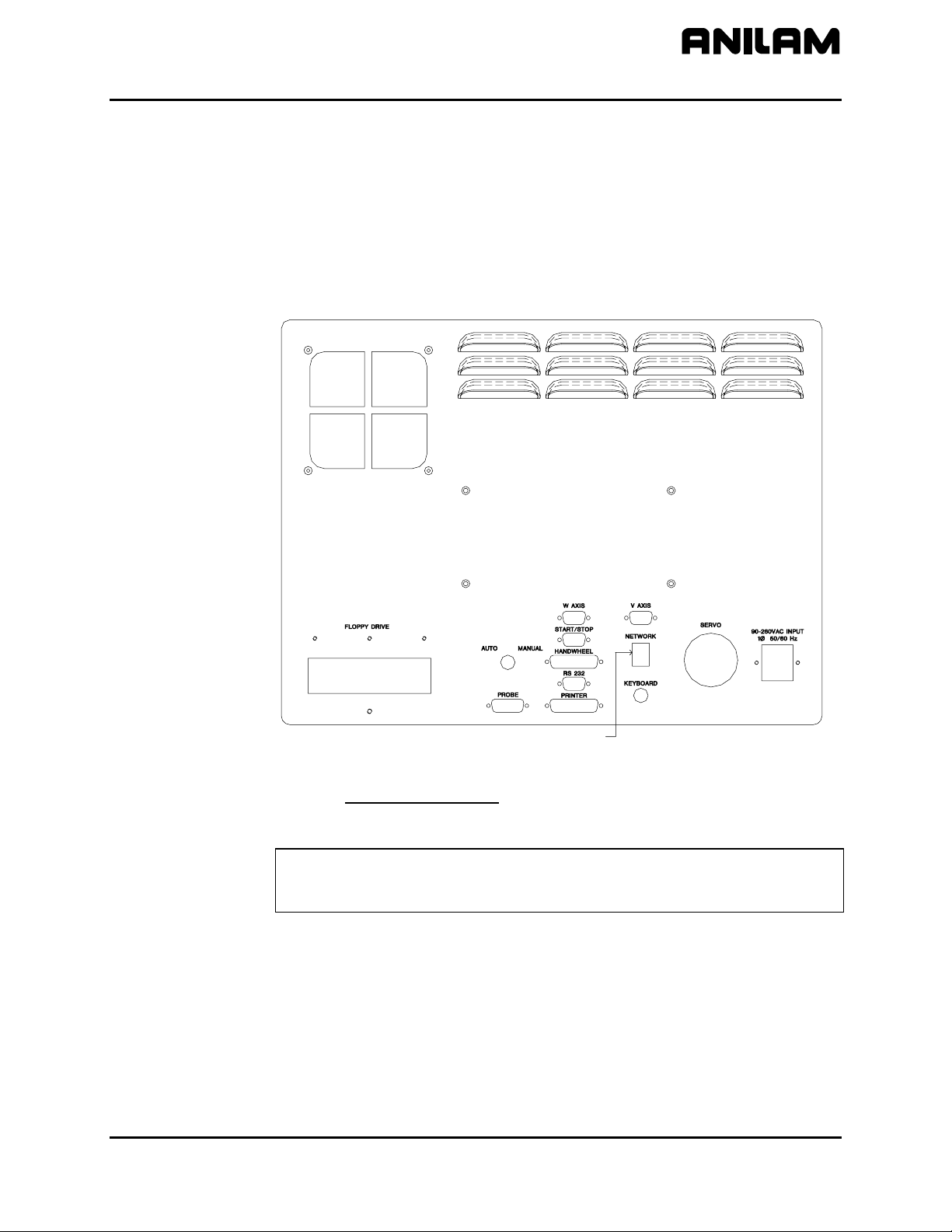
b) Unplug the following harnesses from the card cage and label them
as instructed so that they can be connected properly to the
interface plate. These must be freed from the rest of the harness
assembly so that they can be reused.
i. Remove the scale cables from the Black Tab PCB 514
board. They are X(P8),Y(P9), Z(P10), U(P11), W(P12),
and S(V)(P13).
NOTE: If you have a 3-axis system, then you will connect
S to the U-axis (P11) port.
If you have a 4- or 5-axis system, then the spindle
will connect to V(P13).
ii. Remove the 26-Pin Ribbon or Single Wire cable from the
Blue Tab board PCB 502. Label it P15.
iii. Remove the 10-Pin cable from the Blue Tab Board PCB
502. Label it P7.
iv. Remove the 26-Pin Ribbon or Single Wire cable from the
Red Tab Board PCB 502. Label it P14.
v. Remove the 10-Pin cable from the Red Tab Board PCB
502. Label it P6.
vi. Remove the 110 VAC cable connected to the Power
Supply. Hot, Neutral, and Ground.
c) Remove the RS-232 plug from the servo cabinet wall. It is directly
connected to the card cage and will prevent you from removing it.
d) Remove the card cage assembly from the door. It should come
out with all harnesses attached except the ones removed in the
above steps.
3. Installing the Interface Panel.
a) Mount the interface panel to the door using the 4 nuts and
standoffs supplied.
b) The interface consists of a power supply that supplies the 5 volts
for the encoders or scales, and +/- 15 volts for motion control. It
also has I/O boards based on your systems requirement. (That is,
if your system has M functions, homing, and vectored limits, etc.)
c) Connect the following harnesses, previously removed, to the
interface board.
i. Scale or encoder cables X, Y, Z to P8, P9, P10. U, W, and
S according to instructions in 2b-i. Remove the three wires
in connector P7 pins 1, 2, and 3, and move them to pins 4,
5, and 6, respectively.
ii. Harnesses labeled P6, P7, P14, and P15.
iii. AC harness (P/N 36000271) to TB 1 Terminals 1,2(Gnd -
Green/Yellow), 3,4(Neutral - Blue), and 5,6(Hot - Brown).

5000M Crusader G Upgrade Installation Guide
P/N 70000549B
All rights reserved. Subject to change without notice. 4
14-February-03
iv. Locate the E-Stop wires. Connect the Gray wire to
TB 3-5 Labeled Reset 2. Connect the Brown wire to
TB 3-6 labeled ESSW 2.
4. Connecting the new wiring harness TB3-4 (P/N 33001116 and
P/N 33001117) and Reset TB3-3 wires from the interface to the servo
system.
a) There were a number of versions of servo cabinets, install the two
wires according to the version you have.
b) If your cabinet has a PCB 801 relay board, proceed as follows: If
not, skip to step 5c.
i. Attach the white wire (P/N 33001116) end to TB3-4, and
connect the other end to 24 volt common on PC 803 XG using
the red fork crimp. See 5000M Crusader G Three- and Five-
Axis Upgrade Drawing Package, P/N 70000550, Drawings
30100319 and 30100320.
ii. Remove the Reset switch connection from the PCB 801 P7
connector. Replace with the yellow wire from TB3-3 also
inserted into a 3-position plug. Make sure the yellow wire is
on Pin 3.
5. Connecting the AC Cable (36000271) to the Interface board and
Servo Cabinet.
a) Open the auto/manual switch hole to 11/16” (0.69”). Or, if you
want, you can drill a new hole in any other convenient location.
b) Connect the AC wires to TB1-1, 3, and 5. The same locations as
the other AC cable.
c) Secure the cable inside the servo being careful not to run the
cable close to any other signal wires.
d) Secure the cord retainer in the hole and then leave the cable
ready to connect to the console when mounted.
6. Installing the Servo Interconnect Cable 33001094.
a) Connect the cable using the seal tight fitting to the existing hole on
top of the servo cabinet.
b) Connect the 60-pin connector to P1 of the Interface Board.
7. Installing the W- and V-axis cables.
a) Inside the servo cabinet drill two holes 11/16” (0.69) in size.
Connect the cables marked W (33001166) to the interface board
(P17) and V (33001166) to (P16). Mount the other side to the
servo.

5000M Crusader G Upgrade Installation Guide
P/N 70000549B
All rights reserved. Subject to change without notice. 5
14-February-03
8. Installing the 5000M console:
a) Follow the appropriate directions for your particular mounting kit.
See accompanying sheets. Use existing mounting hardware, if
desired.
b) Connect the AC cable to the rear panel.
c) Connect the Servo Cable 33001094 to the rear panel.
d) Connect the W (36000383) and V (36000383) interconnect cables
between the Console and the cables you previously installed into
the servo.
9. Setting up the Configuration File for the System
Turn on the Console. Go to the Menu Selection Screen. Select
SETUP UTILITY.
The 5000M is configured at the factory to run a standard Crusader M
kit style system. There are non-standard systems that were
manufactured by ANILAM and or other vendors for specific machines
or applications. These systems may require setup parameters to be
changed. If your system differs from the specifications that follow, you
will need to modify the Setup Utility in the appropriate sections. See
the 5000M CNC Setup Utility Manual, P/N 70000509, for further
instructions.
a) Builder Setup – General Axis – Resolution
Set for scales (Linear Encoder) with 0.01 mm (0.0005”) resolution.
If you have a different resolution or are using encoders as
feedback, you will need to modify this.
NOTE: The Z-axis used an encoder on standard systems,
however it is setup as a scale with 0.01mm (0.0005”)
resolution. Do not change it, if this is your situation.
b) Builder Setup – General Axis – In Position:
For scale feedback, match the resolution. Default is .0005”
For encoder feedback set accordingly, usually .0004”.
c) Builder Setup – General Axis – Backlash Compensation:
Default Off for scales.
Make appropriate entries, if using encoder feedback.
d) Builder Setup – General Axis – Encoder Phase:
Default is Not Invert on each axis.
Adjustment may be required after initial setup. Do not enable the
servo until you perform this test and verify proper phasing. Exit
the Setup Utility and Enter the Motion Setup and Testing module.
DO NOT ENERGIZE THE SERVO AT THIS TIME.

5000M Crusader G Upgrade Installation Guide
P/N 70000549B
All rights reserved. Subject to change without notice. 6
14-February-03
Manually move the X, Y, Z, U (or S), W, and S (V)-axis.
Determine if the count is in the proper direction for each axis. If
counting in the opposite direction, set that axis to Invert and test
again.
e) Builder Setup – General Axis – Default Rapid:
Set for 200 IPM.
Adjust accordingly.
f) Builder Setup – General Axis – No Motion Filter Parameters:
Configured for scales on X and Y. Shows a KP value of 3, and a
value of 0in all other settings.
If you are using encoder feedback, enter the values used in the W
Rapid Filter Parameter tables.
g) Builder Setup – General Axis – Vector Limits
Default is Not Enabled.
If you have Vector Limits, enable them accordingly.
h) Builder Setup – Basic I/O Interface – I/O Nodes – Can Node 0
– Inputs (Source)
Configured for Level 1 Inputs as follows:
Active High
External Start (Bit 8)
Stop (Bit 7)
Feed hold (Bit 6)
i) Builder Setup – Basic I/O Interface – I/O Nodes – Can Node 1
– Outputs (Sink)
Configured for Level 1 Outputs as follows:
All Pulse 200ms
M3 = Spindle Forward (Bit 2)
M4 = Spindle Reverse (Bit 3)
M5 = Spindle Off (Bit 1,4)
M8 = Coolant On (Bit 0)
M9 = Coolant Off (Bit 1)
M2 = Spindle and Coolant Off (Bit 1,4)
M30 = Spindle and Coolant Off (Bit 1,4)
If you are using any other combination of inputs and outputs, or
desire a different setup you will need to configure them. These
are configured to control the standard package manufactured by
ANILAM.

5000M Crusader G Upgrade Installation Guide
P/N 70000549B
All rights reserved. Subject to change without notice. 7
14-February-03
j) Level 2 SMT – No entries required in Setup Utility
System pre-wired for standard SMT outputs and Finish Input.
Requires an IPI program to be written. Contact ANILAM
Technical Support for details.
Can Node 0 Inputs (Source)
Finish (Bit 9) Active High
Can Node 1 Outputs (Sink).
SMT 0 (Bit 0)
SMT 1 (Bit 1)
SMT 2 (Bit 2)
SMT 3 (Bit 3)
SMT 4 (Bit 4)
SMT 5 (Bit 5)
Can Node 2 Outputs (Sink)
SMT 6 (Bit 0)
SMT 7 (Bit 1)
S Strobe (Bit 2)
M Strobe (Bit 3)
T Strobe (Bit 4)
k) Tuning the system.
The servo system is ready to be turned on once you have verified
the Setup Utility matches your machine.
Be sure you are prepared to press the EMERGENCY STOP in
case you have not configured the system correctly.
Refer to the 5000M CNC Motion Setup and Testing Manual,
P/N 70000636, for instructions on testing the machine.
Be sure to set the Balance and Signal on each axis.
You need to enter the Motion Setup and Testing section of the
software.
Enable the servo and begin.
After tuning the machine, it will be ready for use.

5000M Crusader G Upgrade Installation Guide
P/N 70000549B
All rights reserved. Subject to change without notice. 8
14-February-03
Network Connection Installation
To install the network connection, plug the standard CAT5, 8-pin, RJ-45
connector into the RJ-45 plug located on the back of the console. The
CNC provides access to network drives via Ethernet.
Procedure:
1. Use a standard CAT5, RJ-45 cable for the network connection.
Refer to Figure 1.
Network Connection
230002252
Figure 1, Console Rear Panel
Refer to CNC Network Setup, P/N 70000483, for an overview of network
setup.
NOTE: A qualified networking engineer must set up the networking
software. Software varies based on the type of network
operating system used.

5000M Crusader G Upgrade Installation Guide
P/N 70000549B
All rights reserved. Subject to change without notice. 9
14-February-03
Remote Start/Stop (Option) Installation
Objective:
To install a remote start/stop pushbutton station on the console.
Tools: Small Flat Screwdriver
Kit:
Part Number Description
33000122 Remote start/stop kit, including preassembled pushbutton
station and a 10-32, 3/8” shoulder bolt, P/N 86100853.
Procedure:
NOTE: You must complete changes to Setup Utility parameters before
you can operate the Remote Start/Stop.
To install the Remote Start/Stop (Option):
1. Locate the Start/Stop pushbutton station and the shoulder bolt,
P/N 86100853.
2. Remove one of the 10-32, black Phillips-head screws on the right side
of the console and replace it with the shoulder bolt.
3. Plug the remote Start/Stop cable into the back of the console at the
START/STOP connector. Refer to Figure 1, Console Rear Panel.
4. Hand-tighten both screws on the connector.
5. Mount the pushbutton station on the shoulder bolt.

5000M Crusader G Upgrade Installation Guide
P/N 70000549B
All rights reserved. Subject to change without notice. 10
14-February-03
Remote Start/Stop Configuration
1. Refer to Figure 2, Remote Start/Stop Setup Map. In Manual Mode
and with the control turned on, press the red Emergency Stop button;
then, press EXIT (F10) to display the Software Options Menu.
2. In the Software Options Menu, highlight Setup Utility, and press
ENTER.
3. The Setup Options Menu, Menu A, activates.
4. Select Builder Setup, and press ENTER.
5. The Builder Setup Menu, Menu B, activates. Select Basic I/O
Interface, and press ENTER.
6. The Basic I/O Interface Setup Menu, Menu C, activates. Select I/O
Nodes, and press ENTER.
7. The I/O Nodes Setup Menu, Menu D, activates. Select DSP2 Node,
and press ENTER. Refer to Figure 3, DSP
2
Node Setup Menu.
8. The DSP2 Input 0 Setup Menu, Menu E, activates. Select Ext Start,
and press ENTER. (The CNC may prompt for a password. If
necessary, enter the service level password, and press ENTER. Refer
to 5000M CNC Setup Utility Manual, P/N 70000509, “Password
Restricted Parameters,” for more information.)
9. The Options Setup Menu, Menu F, activates. Select Active High,
and press ENTER.
10. The DSP2 Input 0 Setup Menu, Menu G, activates. Select BIT (F1),
and press ENTER.
11. The DSP2 Node Setup Menu, Menu H, activates. Select Input 1,
and press ENTER.
12. The DSP2 Input 1 Setup Menu, Menu I, activates. Select Ext Stop,
and press ENTER.
13. The Options Setup Menu, Menu J, activates. Select Active Low.
14. Press EXIT (F10) successively until the Save Changes? prompt
appears in the middle of the screen.
15. Select Yes (F1) to save the changes made.
16. Enter control software and verify that the Start and Stop button on the
push button station function the same way as the green and red
START and STOP keys on the keyboard.
NOTE: The Start/Stop device must be plugged in. If it is not, the inputs
activated above must be set to off.

5000M Crusader G Upgrade Installation Guide
P/N 70000549B
All rights reserved. Subject to change without notice. 11
14-February-03
SoftwareOptions
2.SetupUtility
BuilderSetup
3.BasicI/OInterface
SetupOptions
1.BuilderSetup
StartupScreen
SelectSoftwarePackage
MenuA
SelectSetupMenu
MenuB
BuilderSetupMenu
MenuD
I/ONodesSetupMenu
I/ONodes-Setup
1.DSP2Node
2.CANNode0
3.CANNode1
DSP2Input0-Setup
FunctionStatesCurr.Bit
1.ExtStart
2.ExtStop
3.Auto/Man2
CANI/O
10,000
Yes
BasicI/OInterface-Setup
1.Type................................................
2.Timeout...........................................
3.IssueSpStoponSvoFltorEstop....
4.I/Onodes.........................................
MenuC
BasicI/OInterfaceSetupMenu
33MAP9
1.Off
2.ActiveLow
3.ActiveHigh
MenuE
DSP2Input0SetupMenu
DSP2Node-Setup
1.Input0
2.Input1
3.Input2
Bit
MenuF
DSP2OptionsSetupMenu
MenuG
DSP2NodeSetupMenu
Figure 2, Remote Start/Stop Setup Map

5000M Crusader G Upgrade Installation Guide
P/N 70000549B
All rights reserved. Subject to change without notice. 12
14-February-03
MenuD
I/ONodesSetupMenu
MenuA
SelectSoftwareSetupOption
SoftwareOptions
2.SetupUtility
SetupOptions
1.BuilderSetup
BuilderSetup
1.GeneralAxis
3.BasicI/OInterface
5.Handwheel/DRO
BasicI/OInterface-Setup
5.I/ONodes.................
StartupScreen
MenuB
BuilderSetupMenu
MenuC
BasicInterfaceSetupMenu
DSP2Input0-Setup
FunctionStatesCurr.Bit
1.ExtStart
2.ExtStop
3.Auto/Man2
MenuE
DSP2Input0SetupMenu
1.Off
2.ActiveLow
3.ActiveHigh
MenuF
OptionsSetupMenu
DSP2Node-Setup
1.Input0
2.Input1
3.Input2
MenuH
DSP2NodeSetupMenuMenuJ
OptionsSetupMenu
DSP2Input0-Setup
FunctionStatesCurr.Bit
1.ExtStart0ActiveHigh
2.ExtStop
3.Auto/Man2
DSP2Input1-Setup
FunctionStatesCurr.Bit
1.ExtStart0
2.ExtStop
3.Auto/Man2
I/ONodes-Setup
1.DSP2Node
2.CANNode0..
3.CANNode1..
4.CANNode2..
5.CANNode3..
6.CANNode4..
7.CANNode5..
1.Off
2.ActiveLow
3.ActiveHigh
MenuG
DSP2Input0SetupMenu
MenuI
DSP2Input1SetupMenu
Figure 3, DSP
2
Node Setup Menu

5000M Crusader G Upgrade Installation Guide
P/N 70000549B
All rights reserved. Subject to change without notice. 13
14-February-03
Handy Pulser (Option) Installation
The Handy Pulser (Option) combines the functionality of axis selection,
jog resolution, and a handwheel in a remote device. Refer to the
programming manual for operating instructions on these features.
Installation Procedure
The following procedure describes how to install the Handy Pulser Kit,
P/N 33000949 or 33000965, on 3000M and 5000M Kit style systems.
Kit:
Part Number Description
33000949 for 3-
and 4-axes
systems only
Handy Pulser Kit, including preassembled Handy
Pulser, one 10-32 x 3/8-inch shoulder bolt, P/N
86100853, and mounting bracket, P/N 23000178.
33000965 for 3-,
4-, and 5-axes
systems
Handy Pulser Kit, including preassembled Handy
Pulser, one 10-32 x 3/8-inch shoulder bolt, P/N
86100853, and mounting bracket, P/N 23000178.
Required Tools:
Small, flat screwdriver
To install the Handy Pulser:
1. Locate the preassembled Handy Pulser and the shoulder bolt. Refer
to Figure 4.
Figure 4, Handy Pulser Assembly
2. Facing the console, use the small, flat screwdriver to remove the
10-32, black, Phillips-head screw on the right side of the console.
3. Take the shoulder bolt, P/N 86100853, and place it through the
mounting bracket, P/N 23000178, and the washer, P/N 86300090.
OFF
XZY X1
W
UX100
X10
HANDY PULSER

5000M Crusader G Upgrade Installation Guide
P/N 70000549B
All rights reserved. Subject to change without notice. 14
14-February-03
4. Screw the shoulder bolt into the hole on the right side of the console
and hand-tighten.
5. Hang the Handy Pulser on the bracket.
6. Remove the
E-STOP jumper plug, P/N 33000601, from the HANDWHEEL
connector and store it in a safe place.
NOTE: If the Handy Pulser is not connected to the back of the
console, make sure the E-STOP jumper plug is inserted in the
HANDWHEEL connector.
7. Plug the Handy Pulser cable into the back of the console at the
Handwheel connector. Refer to Figure 1, Console Rear Panel.
Figure 5 illustrates the harness handwheel connector. Table 1
shows the Handy Pulser connector pin assignment
8. Hand-tighten both screws on the connector.
PIN 1
PIN 14
Figure 5, Harness Handwheel Connector
Table 1, Handy Pulser Connector Pin Assignment
Pin Signal Pin Signal
1 Phase A 14 Jog100-8
2 Phase B 15 n.c.
3 +5 VDC 16 Hold In
4 Ground 17 Cool In
5 +24 VDC 18 E-STOP 1
6 X Select-0 19 E-STOP 2
7 Y Select-1 20 E-STOP 3
8 Z Select-2 21 E-STOP 4
9 U Select-3 22 Hold Out
10 n.c. 23 Cool Out
11 W Select-5 24 +24 VDC
12 Jog1-6 25 Shield
13 Jog10-7

5000M Crusader G Upgrade Installation Guide
P/N 70000549B
All rights reserved. Subject to change without notice. 15
14-February-03
Setup Utility Navigation
NOTE: If you purchased your Handy Pulser separately from the CNC,
you must configure Setup Utility parameters before operating
the Handy Pulser. If you purchased your Handy Pulser with the
CNC, Setup Utility parameters are already configured, and you
only need to mount the Handy Pulser.
The Setup Utility provides access to all CNC settings through a layered
organization of menus. Each menu contains a list and provides access to
configuration settings or another menu. To select a listed choice,
highlight the selection. Press ENTER to activate the highlighted selection.
For some settings, press ENTER to toggle the setting On or Off. Other
settings require you to enter a specific value. To automatically save a
highlighted setting, press ENTER or press Exit (F10). To return to a
previous menu, close the current menu by pressing F10.
Handy Pulser Setup
NOTE: Some steps in these procedures may require you to enter a
service-level password. Refer to 5000M CNC Setup Utility
Manual, P/N 70000509, “Password Restricted Parameters.”
To configure the handwheel in the Handy Pulser:
1. Refer to Figure 6, 5000M Handy Pulser Setup Menus. In Manual
Mode or Power-Up Mode, press EXIT (F10) to display the Software
Options Menu.
2. In the Software Options Menu, highlight Setup Utility, and press
ENTER. The Setup Options Menu, Menu A, is displayed.
3. Highlight Builder Setup, and press ENTER.
4. In the Builder Setup Menu, highlight Handwheel/DRO, and press
ENTER. The Handwheel/DRO Setup Menu, Menu C, is displayed.
5. Highlight Handwheel/DRO #1, and press ENTER. The Handwheel
DRO #1 Setup Menu, Menu D, is displayed.
6. Verify that Type is set to Handwheel. If necessary, press ENTER to
display the Options popup menu, and select Handwheel.
7. Highlight Handwheel in the Handwheel DRO #1 Setup Menu, and
press ENTER. The Handwheel Setup Menu, Menu E, is displayed.
8. Highlight Scaling Factor, and press ENTER.
9. Type the Scaling Factor (usually 1.00), and press ENTER.
10. Press EXIT (F10) successively until the Save Changes? prompt is
displayed in the middle of the screen.
11. Select Yes (F1) to save the changes.
The handwheel is now ready for use.

5000M Crusader G Upgrade Installation Guide
P/N 70000549B
All rights reserved. Subject to change without notice. 16
14-February-03
Figure 6, 5000M Handy Pulser Setup Menus
MenuB
5000M4XBuilderSetupMenu
MenuB
5000M5XBuilderSetupMenu
5000MHPULSER
MenuB
5000M3XBuilderSetupMenu
Builder
Setup
1.GeneralAxis
2.SpindleAxis
3.BasicI/OInterface
4.Prog.I/OInterface
5.Handwheel/DRO
MenuC
Handwheel/DRO-SetupMenu
MenuA
SetupOptionsMenu
Setup Options
1. Builder Setup
StartupScreen
SoftwareOptionsMenu
2. Setup Utility
Software Options
Menu D
Handwheel/DRO #1 - Setup Menu Options
None
Handwheel
Linear DRO
Rotary DRO
Coupled DRO
Menu E
Handwheel #1 - Setup Menu
Handwheel
#1-
Setup
1.ScalingFactor.........1.00
Handwheel/DRO-Setup
1.
Handwheel/DRO#1.......
2.
Handwheel/DRO
#2.......
4.CoupledDROTolerance..0.00000
Handwheel/DRO
#1-
Setup
1.Type.....................Handwheel
2.Phase.....................NotInvert
3.
Handwheel..
4.DRO.............
Builder
Setup
2.UAxis
3.SpindleAxis
4.BasicI/OInterface
5.Prog.I/OInterface
6.Handwheel/DRO
Builder
Setup
4.BasicI/OInterface
5.Prog.I/OInterface
6.
Handwheel/DRO

5000M Crusader G Upgrade Installation Guide
P/N 70000549B
All rights reserved. Subject to change without notice. 17
14-February-03
Peripherals Installation
Printer Installation
Plug the printer cable into the DB-25 connector on the back of the
console. Refer to Figure 1, Console Rear Panel.
Keyboard Installation
Plug any standard PC keyboard into the 5-pin mini-DIN socket on the
back of the console. Refer to Figure 1, Console Rear Panel. (Use a
size adapter, if required.) Installing a keyboard deactivates the console
keypad. To reactivate the keypad, unplug the keyboard.
The operator cannot activate the E-STOP function or reset the servos
using an external keyboard. These functions require the corresponding
keys on the console keypad.
NOTE: ANILAM recommends industrial grade keyboards.
Maintenance Procedures
Objectives:
To replace the console fan filter.
Tools: Phillips Screwdriver
Parts:
Table 2, Console Rear Panel Parts, lists the parts needed to replace the
console fan filter.
Procedure:
Perform the procedure for the console rear panel filter you need to
replace.
NOTE: ANILAM provides replacement filters P/N 85300009 with each
5000M Crusader G Upgrade.

5000M Crusader G Upgrade Installation Guide
P/N 70000549B
All rights reserved. Subject to change without notice. 18
14-February-03
Replace the Console Rear Panel Filter, P/N 85300009
Refer to Figure 7. Table 2 lists the parts shown in Figure 7.
To replace the console fan filter:
1. Remove the screws that hold the frame to the rear panel of the
console.
2. Replace the console filter, and reattach the frame.
Inspect rear panel filter and verify the fan’s airflow monthly. ANILAM
recommends that you replace the console filter every three months.
However, under some adverse environmental conditions, such as oil
vapor contamination and/or high levels of particulate, more frequent filter
changes may be required. The suggested interval, in such cases, is once
a month.
Figure 7, Console Rear Panel – Inside View
Table 2, Console Rear Panel Parts
Item Part Number Description Qty.
1 23000225 Console, Rear Panel, 5000M Crusader G 1
2 85400011 Fan, 12VDC, 0.72 A, 105 CFM 1
3 85400013 Fan Finger Guard 1
4 85300009 Filter, POLY-U 1
5 21900112 Bracket, Fan Filter, Console 1
6 86100238 Screw, #6-32 x 1-7/8” LG PHL PAN HD 4
7 86100166 Screw, #6-32 x 5/8” LG PHL PAN HD, BLK 4
PANEL INSIDE
Other manuals for 5000M
1
Table of contents