HIRED-HAND 6607-8036 User manual

Manual No. 4801-2994 Rev 10-05 Installation & Operation Manual Feed Manager
Feed Manager
Hired Hand Manufacturing, Inc.
1733 County Road 68
PO Box 99
Bremen, Alabama 35033

Manual No. 4801-2994 Rev 10-05 FEED MANAGER Table of Contents
Table of Contents
Section Title Page
1. Ratings and Specifications.............................................................................................................................3
2. Warnings .......................................................................................................................................................3
3. Limited Warranty ..........................................................................................................................................4
4. Introduction ...................................................................................................................................................5
4.1 Features...................................................................................................................................................5
4.2 System Limitations.................................................................................................................................5
5. Feed Manager Front Panel.............................................................................................................................5
5.1 Mode, + and - Buttons and Main Display..............................................................................................6
5.2 Feed Bin #1, #2, #3, and #4 Buttons and Indicators...............................................................................6
5.3 Alarm Indications ...................................................................................................................................7
6. Programming the Feed Manager ...................................................................................................................8
6.1 P1 – P9 General Parameters ...................................................................................................................8
6.2 P10.x – P19.x Feed Bin Characteristics................................................................................................10
6.3 P40 – P49 Hired-Hand Network...........................................................................................................10
6.4 PS1 – PS9 Sensor Readings..................................................................................................................11
7. Feed Manager Control / Editor Section.......................................................................................................11
7.1 Feed Level ............................................................................................................................................12
7.2 Feed Capacity (%) ................................................................................................................................12
7.3 Bin Status..............................................................................................................................................12
7.4 Min. Feed Capacity (%)........................................................................................................................13
7.5 Max. Fill Time (Minutes) .....................................................................................................................13
8. Wiring Diagrams, Schematics, etc...............................................................................................................15
8.1 Feed Manager Circuit Board Layout....................................................................................................15
8.2 Connecting AC Power to the Feed Manager........................................................................................16
8.3 Connecting Feed Bins to the Feed Manager.........................................................................................17
8.4 Connecting a Current Sensor or Sens-O-Matic III to the Feed Manager ............................................18
8.5 Connecting an Alarm to the Feed Manager..........................................................................................19
8.6 Connecting the Feed Manager to the HH.Net.......................................................................................20
9. Replacement and Optional Parts..................................................................................................................21
10. NOTES........................................................................................................................................................22
Part No. 4801-2994 Rev 10-05 FEED MANAGER Page 3 of 22
1. Ratings and Specifications
•Temperature Range…………..32°F - 122°F (0°C – 50°C)
HHI Part
Number Description Power Supply Temperature
6607-8036 Feed Manager 120/230 VAC 50/60 Hz 32° F thru 122°F
(0° C thru +50° C)
2. Warnings
Warning!
Only a certified electrician should install or maintain electrical connections.
Warning!
Proper safety equipment must be used during installation of Feed Level Sensor.
Warning!
Do not install or maintain equipment during a lightning storm.
Warning!
Maximum operating temperature of Feed Manager is 0°to +50°C (32°to 122°F).
Maximum operating temperature of Feed Level Sensor is -18°to +54°C (0°to 130°F).
Warning!
When this system is used in a life sustaining application where failure could result
in loss or injury, the user should provide adequate back-up, or accept the risk of
such loss or injury!

Part No. 4801-2994 Rev 10-05 FEED MANAGER Page 4 of 22
3. Limited Warranty
All products are warranted to be free from defects in material and workmanship for a period of one
year from the date of purchase if installed and used in strict accordance with the installation
instructions. Liability is limited to the sale price of any products proved to be defective or, at
manufacturers’ option, to the replacement of such products upon their return. No products are to be
returned to the manufacturer, until there is an inspection and/or a return-goods authorization (RGA)
number is issued.
All complaints should be directed first to the authorized distributor who sold the product. If
satisfaction is not obtained or the name of the distributor is not known, write the manufacturer that
appears below, directed to the attention of Customer Service Manager.
This limited warranty is expressly in lieu of any and all representations and warranties expressed or
implied, including any implied warranty of merchantability or fitness for a particular purpose. The
remedy set forth in this limited warranty shall be the exclusive remedy available to any person. No
person has authority to bind the manufacturer to any representation or warranty other than this limited
warranty. The manufacturer shall not be liable for any consequential damages resulting from the use
of our products or caused by any defect, failure or malfunction of our products. (Some areas do not
allow the exclusion or limitation of incidental or consequential damages, so the above limitation or
exclusion may not apply to you.)
This warranty gives you specific legal rights and you may also have other rights that vary from area
to area.
Warrantor:
Hired-Hand Manufacturing, Inc.
1733 County Road 68
PO Box 99
Bremen, Alabama 35033

Part No. 4801-2994 Rev 10-05 FEED MANAGER Page 5 of 22
FEED MANAGER
Mode Indicators Mode Button Option Selection Buttons
Feed Level
Indicators
Auger #2
Fill Indicator
Auger #1
Fill
Indicator Main
Display
Bin #1
Selection
Button
4. Introduction
The Feed Manager is the latest technology in the Hired-Hand controller family. This technology adds the
stand-alone controller capability for monitoring feed levels in bins and run times of feed augers. One Feed
Manager controller can monitor up to four feed bins and two feed augers from two buildings. Beyond
monitoring, it also adds alarm features to help detect feed spills or prevent running out of feed. The ultrasonic
Feed Level Sensors (sold separately) are connected to the Feed Manager to monitor the feed inventory in the
feed bins. The Feed Manager can be connected to a Sens-O-Matic III or Current Sensor (sold separately) to
monitor runtimes of Feed Augers.
4.1 Features
•Input Device Options
Up To 4 Feed Bin Level Sensors (Required) 2 Feed Auger Runtime Sensors (Optional)
HHNet connection for PC compatibility
•Output Devices (Standard)
1 Alarm relay with both N.O. and N.C. contacts
4.2 System Limitations
The Feed Level System is intended to provide a low-cost alternative to load-cell systems for monitoring feed
inventory. It is not an accurate way to track feed consumption or to accomplish restrictive feeding.
This system will provide an estimated feed weight although it is simply estimated. There are many factors
which will cause day to day errors in this estimate. These factors include coning and inaccurate feed density. It
is important to understand that errors in level will occur from time to time due to coning. These errors should
be limited to damp starter feed, therefore, the system should provide accurate readings in almost all cases.
Important Note:
In order to maintain consistent feed levels, the Feed Manager uses a “Rate Filter”. This filter only allows
small changes in the “Feed Level” per second. This technique will slow the reaction time. Therefore, once
installed, allow approximately 20 minutes for the reading to stabilize.
5. Feed Manager Front Panel
The Feed Manager front panel includes four columns of feed level LED indicators with individually selectable
push-button switches directly beneath each column. To the left and right sides of the front panel are the Auger
Fill Indicators. Mode indicators, mode button, and option selection buttons are located to the lower right side
of the front panel.

Part No. 4801-2994 Rev 10-05 FEED MANAGER Page 6 of 22
Feed Level
Indicators
Auger #2
Fill
Indicator
Auger #1
Fill
Indicator
Feed Bin #3
Selection
Button
5.1 Mode, + and - Buttons and Main Display
Mode Button – The Mode button is used to select a controller function. Press the Mode button to toggle
between specific feed bins and functions. The Mode Indicators light when a function is selected and
the associated data is displayed in the Main Display. By pressing and holding the Mode button for at
least 5 seconds, the Feed Manager can be placed in the Program Mode as discussed in Section 6 of
this manual.
Plus and Minus Buttons – The plus (+) and minus (-) buttons are used to change or modify a variable's value.
5.2 Feed Bin #1, #2, #3, and #4 Buttons and Indicators
Feed Level Indicators – The Feed Manager includes four columns of feed level LED indicators. As the feed
level inside the feed bin decreases, the Feed Level Indicators also decrease and change color
accordingly. As the feed continues to decrease and the third LED from the bottom turns Off, the two
remaining LED’s will change colors. First, both will be orange; then one orange and one red; two
red; one red; and finally all LED’s will be OFF.
Feed Bin Selection Buttons – Individually selectable push-button switches are located directly beneath each
column of Feed Level Indicators. Pressing a specific switch will allow direct access to the specific
feed bin’s Feed Level, Feed Capacity, and Bin Status. Pressing the Mode switch repeatedly allows
sequential access to each feed bin.
Auger Fill Indicator – To the left and right sides of the front panel are the Auger Fill Indicators. When this
option is used and the Feed Manager is connected to a Current Sensor, the Fill Indicator will turn ON
when the Auger motor is running and OFF indicates the motor is not running.
Function Modes
Mode Indicators
Minus button
(Use to decrease
value of variable)
Plus button
(Use to increase
value of variable)
Mode Select Button
Main Display
1 2 3 4

Part No. 4801-2994 Rev 10-05 FEED MANAGER Page 7 of 22
5.3 Alarm Indications
Normal Operation – During normal operation with no alarms present and no specific feed bin or specific
operation selected, the following indications will be shown:
•The Main Display will continuously show the active feed bin numbers.
•The Feed Level Indicators for the active bins will be displaying the feed levels.
•The Auger Fill Indicators will either be solid-ON when the auger motor is running or solid-
OFF when the auger motor is not running.
Minimum Feed Capacity Alarm –The
Min. Feed Capacity feature
monitors the amount feed in the
feed bin and will activate the
Auxiliary Alarm output if the feed
decreases below the selected
amount of minimum feed. Refer to
Section 7.4 for control/editing the
Min. Feed Capacity settings.
When the feed level decreases
below the Min. Feed Capacity (%)
percentage, the specific Feed Bin
Level Indicators will immediately
start flashing.
NOTE:The feed level must continuously remain below the Min. Feed Capacity (%) percentage for
a minimum of 4 minutes for the Auxiliary Alarm to activate.
After 4 minutes, the Auxiliary Alarm contacts will activate, the Main Display will alternate between
showing the active Feed Bins and “Err” (“Err” represents that an Error/Alarm condition exists), and
the specific Feed Bin Level Indicators will continue to repeatedly flash ON and OFF. When the feed
level rises above the Minimum Feed Capacity (%), the Auxiliary Alarm, Feed Bin Level Indicators,
and display immediately return to normal operation.
Maximum Fill Time Alarm – The Max. Fill Time feature monitors the amount of time which the feed augers
remain ON and will activate the Auxiliary Alarm output if the feed auger remains ON longer than the
selected Max. Fill Time limit. Refer to Section 7.5 for control/editing the Max. Fill Time settings.
When the feed auger initially turns ON, the Fill Indicator will also turn ON. If either of the feed
augers remain ON longer than the selected Max. Fill Time (minutes), the Auxiliary Alarm contacts
will activate. When the Auxiliary Alarm is activated, the specific Auger Fill Indicator will
repeatedly flash ON and OFF. The Main Display will also alternate between the active feed bins and
Mode Indicators
Feed Level
Indicators
Auger #2
Fill Indicator
Auger #1
Fill
Indicator Main
Display

Part No. 4801-2994 Rev 10-05 FEED MANAGER Page 8 of 22
“Err” representing that an Error/Alarm condition exists. As soon as the alarm condition clears, the
Auger Fill Indicator and Main Display return to normal operation.
NOTE: A Current Sensor (6407-6070 ordered separately) or Sens-O-Matic III feed controller (6606-
2000 for a 120vac model or 6606-2100 for a 230vac model ordered separately) is required for
this function.
6. Programming the Feed Manager
This section introduces the Feed Manager programming software. The Feed Manager controller software
allows the use of four ultrasonic feed level sensors (sold separately) while also monitoring two feed augers.
The feed level sensors are used to monitor the feed inventory in the feed bins. The feed auger connections are
used primarily to monitor the runtime of the cross-fill auger motors. The feed augers can only be monitored
when used with a Current Sensor or Sens-O-Matic III feed switch (sold separately). The following figure
shows the Feed Manager programming options which must be carefully selected to allow accurate monitoring
of the Feed Level. By pressing and holding the Mode button for at least 5 seconds, the Feed Manager can be
placed in the Program Mode as discussed below and on the following pages.
In addition to the feed level capabilities, the optional use of a Current Sensor or Sens-O-Matic III adds a new
alarm feature. The alarm allows you to place a runtime limit on each auger motor to help the user detect feed
spills or protect against running out of feed. If the runtime limit is exceeded, the auxiliary alarm will be
triggered.
FEED MANAGER PROGRAMMING
P 1-9 General Parameters
P1 = Metric Units
YES = Metric Units
NO = English Units
P2 = Feed Sensors Activated
P3 = Feed Sensor Type
P4 = Feed Sensor Dead Zone (ft, m)
P5 = Reset Feed Levels
YES = Reset To Zero
NO = Do Not Reset
P10.x - P19.x Feed Bin Characteristics
‘x’ Represents Bin Number
P10.x = Bin x Diameter (6’, 7’, 9’, 12’)
P11.x = Bin x - # of Rings
P12.x = Bin x Ring Height (Typ. 2.65’ [0.81m])
P13.x = Bin x Cap Angle (30°, 40°)
P14.x = Estimated Bin x Height
P15.x = Estimated Bin x Weight (ton,mton)
P40 - P49 Hired-Hand Network
P40 = HHNET Network Address
P41 = Software Version Number
P42 = Controller Setup
PS1 - PS9 Sensor Readings
PS1 = Feed Sensor 1
PS2 = Feed Sensor 2
PS3 = Feed Sensor 3
PS4 = Feed Sensor 4
6.1 P1 – P9 General Parameters
General parameters are associated with the operation and control of the Feed Manager. These settings should
be entered when the system is installed:
P1 – Metric Units
The units of measure can be selected as either English or Metric Units. Select ‘No’ and measurements
display in English Units. Select ‘Yes’ and measurements display in Metric Units.
Measurement English Metric
Feed Level Feet Meters
Ring Height Feet Meters
Bin Height Feet Meters
Bin Weight Tons Mtons
Dead Zone Feet Meters

Part No. 4801-2994 Rev 10-05 FEED MANAGER Page 9 of 22
P2 – Feed Sensors Activated
This general parameter is used to turn additional feed bins ON (press the ‘+’ button) or OFF (press the ‘-‘
button). For example, if you only have two feed bin sensors connected to this control, you can disable bins
#3 and #4 displays by setting this to “1 2 - -“.
P3 – Feed Sensor Type
Program selection not available at this time.
P4 – Feed Sensor Dead Zone (ft, m)
Dead Zone refers to the area that the sensor is hanging into the feed bin. The figure below shows how to
measure the Dead Zone. The measurement should be taken from the top of the cap (excluding the lid ring)
to the bottom of the sensor probe. This measurement is the Dead Zone that should be entered.
P5 – Reset Feed Levels
Select ‘Yes’ to reset the feed bin level. The feed level indicators will reset to the lowest level and
gradually climb to the current feed level.
Dead Zone

Part No. 4801-2994 Rev 10-05 FEED MANAGER Page 10 of 22
6.2 P10.x – P19.x Feed Bin Characteristics
Feed bin characteristics are the specific feed bin parameters required to monitor feed bins:
“x” Represents Bin Number
P10.x – Diameter (6’, 7’, 9’, 12’)
Feed Bin #x diameter.
P11.x – # of Rings (1, 2, 3, 4, 5)
Feed Bin #x number of rings.
P12.x – Ring Height (Typ. 2.65’ [0.81m])
Feed Bin #x Ring Height = Measurement from the top/center of one ring to the top/center of the next ring.
Selection Range of English = 1.00’ to 3.50’. Selection Range of Metric = 0.30 to 1.07. The “Ring
Height” can also be used to adjust any errors in controller calculations.
P13.x – Cap Angle (30º or 40º)
Feed Bin #x cap angle at the top of the bin.
P14.x – Estimated Bin Height
Feed Bin #x bin height. The bin height is calculated by using the entered bin size information. This can be
verified by measuring from the top of the boot to the top of the cap (excluding the lid ring). Refer to the
figure on titled Feed Bin Specs. If the “Bin Height (P14.x)”, is incorrect, adjustments can be made to the
“Ring Height” for correction.
P15.x – Estimated Bin x Weight (ton, mton)
Feed Bin #x feed weight. The feed weight is calculated by using the entered bin size information and the
current feed level module results. “Feed Weight (P15.x)” displays the estimated weight of the feed
currently in the bin based on a feed density of 40 lbs/cu. ft.
6.3 P40 – P49 Hired-Hand Network
These parameters are used with Hired-Hand’s Farm Manager Software. The controller has three parameters
which are used to function with the Hired-Hand PC compatible inter-controller network (HH.Net).
P40 – HHNet Network Address
HH.Net permits up to 32 controllers to be addressed on a single communications port of a personal
computer (PC). In order for the computer to recognize the communications from the controllers, each
controller must have a unique network address.
P41 – Software Version Number
This is not settable by the user. It is the version of the controller software.
Top Angle
Bin
Height
Ring
Height
Number of
Rings
Dead Zone
F
Fe
ee
ed
d
B
Bi
in
n
S
S
p
pe
ec
cs
s
Diameter

Part No. 4801-2994 Rev 10-05 FEED MANAGER Page 11 of 22
P42 – Controller Setup
This is not settable by the user. It is a unique number that allows the network software (Farm Manager) to
recognize the type of controller.
6.4 PS1 – PS9 Sensor Readings
The Feed Manager will accommodate up to four Feed Level Sensors. The sensor reading will display for PSx
where xis the sensor number. This is a precise reading used mainly for troubleshooting purposes.
NOTE: As the feed level decreases, the sensor reading number will increase (Range = 0 thru 255).
PS1 – Feed Sensor 1
This is the sensor reading for Feed Sensor 1.
PS2 – Feed Sensor 2
This is the sensor reading for Feed Sensor 2.
PS3 – Feed Sensor 3
This is the sensor reading for Feed Sensor 3.
PS4 – Feed Sensor 4
This is the sensor reading for Feed Sensor 4.
7. Feed Manager Control / Editor Section
The Feed Manager Control / Editor Section includes five Mode Indicator LED’s, a Main Display, Mode Select
button, and Plus and Minus editor buttons.
When a specific feed bin is selected, the Feed Level Indicators for the specific bin will flash and the other
remaining feed bin level indicators will be OFF. After approximately 20 seconds of inactivity, the controller
will exit the Control / Editor mode and return to display all active feed bins. The following functions can be
scrolled-thru by using the Mode Select Button or by first pressing the specific Bin Selection Button (1, 2, 3, or
4).
Function Modes
Mode Indicators
Minus button
(Use to decrease
value of variable)
Plus button
(Use to increase
value of variable)
Mode Select Button
Main Display
1 2 3 4

Part No. 4801-2994 Rev 10-05 FEED MANAGER Page 12 of 22
2 5
7.1 Feed Level
When the Feed Level indicator is ON,
the Main Display will show the
amount of feed remaining in the
specific feed bin. The Feed Level is
shown in number of feet or meters
from the feed bin’s boot. The unit of
measure (Feet or Meters) can be set in
the Program P1 setting (Refer to
Section 6.1). View the Feed Level by
pressing the specific required Bin
Selection Button (1, 2, 3, or 4). The
specific Feed Bin Level Indicators
will repeatedly flash to indicate the
selected feed bin.
7.2 Feed Capacity (%)
When the Feed Capacity indicator is
ON, the Main Display will show the
percentage of feed remaining in the
specific feed bin. View the Feed
Capacity by first pressing the
specific required Bin Selection
Button (1, 2, 3, or 4). The specific
Feed Bin Level Indicators will
repeatedly flash to indicate the
selected feed bin. Next, press the
Mode select button once until the
Feed Capacity indicator turns ON.
7.3 Bin Status
The selectable Bin Status is used to
turn a specific feed bin’s alarm either
ON or OFF. The feed Bin Status can
be turned OFF (Minus – button) to
disable the Minimum Feed Capacity
alarm and prevent this alarm from
reoccurring until the Bin Status is
manually turned ON (Plus + button).
To view or change the Bin Status,
first press the specific required Bin
Selection Button (1, 2, 3, or 4). The
specific Feed Bin Level Indicators
will repeatedly flash to indicate the
selected feed bin. Next, press the
Mode select button twice until the
Bin Status indicator turns ON. The
Main Display will show the
selectable Bin Status of the specific
feed bin.
Feed Level
5.3
Feed Capacity
Bin Status

Part No. 4801-2994 Rev 10-05 FEED MANAGER Page 13 of 22
7.4 Min. Feed Capacity (%)
The Min. Feed Capacity feature
monitors the amount feed in the feed
bins and will activate the Auxiliary
Alarm output if the feed decreases
below the selected amount of minimum
feed. When the feed level decreases
below the Min. Feed Capacity (%)
percentage, the specific Feed Bin Level
Indicators will immediately start
flashing. To view or change the Min.
Feed Capacity setting, press the Mode
Select button repeatedly until the
Minimum Feed Capacity indicator
turns ON.
The Main Display shows the selectable Minimum Feed Capacity percentage for ALL of the active feed bins.
For example, if 30 is selected, the Auxiliary Alarm will activate if the Feed Capacity decreases to 29% or less
overall feed bin capacity.
To increase or decrease the Minimum Feed Capacity percentage, press the Plus + or Minus - button until the
desired value is shown in the Main Display. To turn the Minimum Feed Capacity function OFF for ALL
Feed Bins, repeatedly press the Minus - button until OFF is shown in the Main Display. To disable the
Minimum Feed Capacity alarm only for specific feed bins, turn Bin Status OFF while the specific feed bin is
selected. Refer to Section 7.3.
NOTE:The feed level must continuously remain below the Min. Feed Capacity (%) percentage for a
minimum of 4 minutes for the Auxiliary Alarm to activate.
After 4 minutes, the Auxiliary Alarm contacts will activate, the Main Display will alternate between showing
the active Feed Bins and “Err” (“Err” represents that an Error/Alarm condition exists), and the specific Feed
Bin Level Indicators will continue to repeatedly flash ON and OFF. When the feed level rises above the
Minimum Feed Capacity (%), the Auxiliary Alarm, Feed Bin Level Indicators, and display immediately
return to normal operation.
NOTE: In order for the Minimum Feed Capacity function to be operational, the Bin Status mode must be
turned ON for each required feed bin AND the Min. Feed Capacity (%) must be set to the desired
percentage.
7.5 Max. Fill Time (Minutes)
The Max. Fill Time feature is used
provide an alarm in cases of
excessive feed auger runtimes as a
result of feed spills and/or equipment
malfunction. Max. Fill Time
monitors the amount of time which
the feed augers remain ON and will
activate the Auxiliary Alarm output
if the feed auger remains ON longer
than the selected Max. Fill Time
limit. When the feed auger initially
turns ON, the Fill Indicator will also
turn ON.
If either of the feed augers remain ON longer than the selected Max. Fill Time (minutes), the Auxiliary Alarm
contacts will activate. When the Auxiliary Alarm is activated, the specific Auger Fill Indicator will
repeatedly flash ON and OFF. The Main Display will also alternate between the active feed bins and “Err”
representing that an Error/Alarm condition exists. As soon as the alarm condition clears, the Auger Fill
Indicator and Main Display return to normal operation.
3 0
Min Feed Capacity
Max. Fill Time
1 5

Part No. 4801-2994 Rev 10-05 FEED MANAGER Page 14 of 22
For example, if 15 is selected, the Auxiliary Alarm will activate if the run time exceeds 15 minutes.
To increase or decrease the Max. Fill Time minutes, press the Plus + or Minus - button until the desired value
is shown in the Main Display. To turn the Max. Fill Time function OFF for both feed auger motors, repeatedly
press the Minus - button until OFF is shown in the Main Display.
To view or change the Max. Fill Time setting, press the Mode Select button repeatedly until the Max. Fill
Time indicator turns ON.
NOTE: A Current Sensor (6407-6070 ordered separately) or Sens-O-Matic III feed controller (6606-2000 for
a 120vac model or 6606-2100 for a 230vac model ordered separately) is required for this function.

Part No. 4801-2994 Rev 10-05 FEED MANAGER Page 15 of 22
8. Wiring Diagrams, Schematics, etc.
The following diagrams describe the Feed Manager circuit board connections and how the Feed manager is
connected to external equipment.
8.1 Feed Manager Circuit Board Layout
HH.Net
1.2 Amp Slo-Blow Fuse – F1
Auxiliary
Alarm
AC Power
Connector
Net Term
Jumper
Voltage
Selector
Switch
Auger #1
Auger #2
Feed Bin # 1
Feed Bin # 2
Feed Bin # 3
Feed Bin # 4
Option Board
Connection
Processor

Part No. 4801-2994 Rev 10-05 FEED MANAGER Page 16 of 22
8.2 Connecting AC Power to the Feed Manager
Inset A
Feed Manage
r
Inset B
WARNING:
Ensure that the Voltage Selector Switch
shown in Inset B is set according to the
AC Supply voltage. Equipment damage
will occur if this switch is not set
correctly.
Inset B
OR

Part No. 4801-2994 Rev 10-05 FEED MANAGER Page 17 of 22
8.3 Connecting Feed Bins to the Feed Manager
Feed Manager
Circuit Board Connections
(Exploded View)
Feed Level Sensor
(Mounted on top of
the feed bin)
Cable from the feed
bin to the controller
Feed Bin #4
Feed Bin #1
Feed Bin #2
Feed Bin #3
Shield
Vdc
Sig
Gnd
Feed Manage
r
Inset A
Inset
A
Part No. 4801-2994 Rev 10-05 FEED MANAGER Page 18 of 22
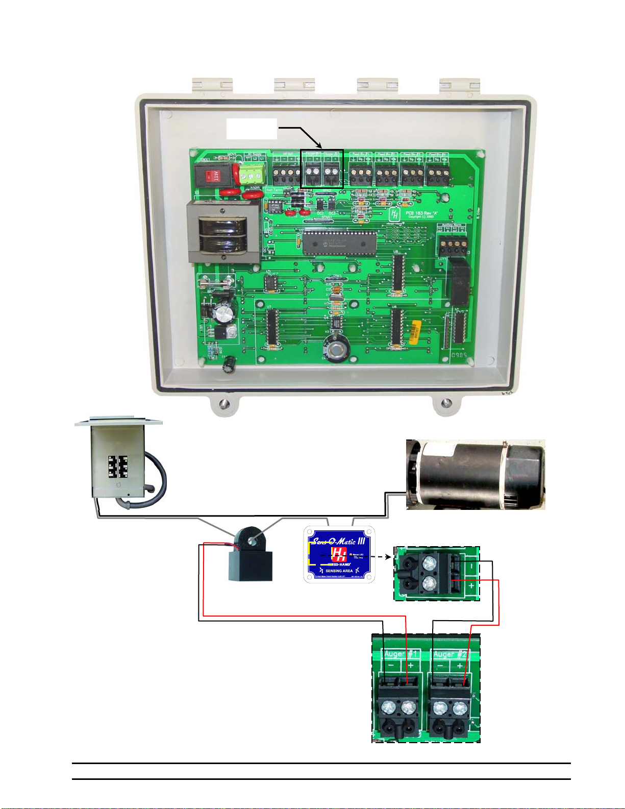
8.4 Connecting a Current Sensor or Sens-O-Matic III to the Feed Manager
Current
Sensor
Feed Auger Motor
L2
L1
Feed Manager
Auger #1 and
Auger #2 Circuit
Board
Connections
(Exploded View)
Black
Red
Feed Manage
r
Inset A
OR
Inset
A
Sens-O-Matic III Circuit Board
Run Sensor Connections (Exploded View)
NOTE: Either a Current Sensor or a
Sens-O-Matic III may be
used to monitor the Feed
Auger Motor Runtime.
Run Sensor
Auger #1 Auger #2
Breaker Box

Part No. 4801-2994 Rev 10-05 FEED MANAGER Page 19 of 22
8.5 Connecting an Alarm to the Feed Manager
Feed Manage
r
Inset A
For Parallel
Alarm Connection For Series
Alarm Connection
Internal Circuit Board
Auxiliary Alarm Relay
NOTE: The internal wiring shows the condition of
the relay during normal conditions (no
alarm present). During an alarm
condition, the contact positions will be
reversed.

Part No. 4801-2994 Rev 10-05 FEED MANAGER Page 20 of 22
8.6 Connecting the Feed Manager to the HH.Net
Inset A
Inset B
Feed Manage
r
Table of contents
Popular Network Hardware manuals by other brands

Juniper
Juniper SSR1400 quick start guide

PowerFile
PowerFile Active Archive Appliance A3 installation guide

SonicWALL
SonicWALL ECLASS NSA E8500 Getting started guide

Cabletron Systems
Cabletron Systems W85 user guide

GUILCOR
GUILCOR WebSensor user guide

Mellanox Technologies
Mellanox Technologies MUA9002F-2SF-250 user manual


