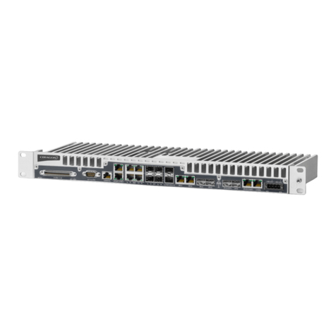
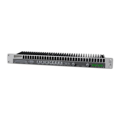
Ceragon Fibe-Air IP-10G User manual

Copyright © 2012 by Ceragon Networks Ltd. All rights reserved.
FibeAir® IP-10G
Installation Guide
Doc-00023199 Rev E
June 2012

FibeAir® IP-10G Installation Guide
Ceragon Proprietary and Confidential Page 2 of 71
Notice
This document contains information that is proprietary to Ceragon Networks
Ltd. No part of this publication may be reproduced, modified, or distributed
without prior written authorization of Ceragon Networks Ltd. This document
is provided as is, without warranty of any kind.
Registered Trademarks
Ceragon Networks® is a registered trademark of Ceragon Networks Ltd.
FibeAir® is a registered trademark of Ceragon Networks Ltd. CeraView® is a
registered trademark of Ceragon Networks Ltd. Other names mentioned in
this publication are owned by their respective holders.
Trademarks
CeraMap™, PolyView™, EncryptAir™, ConfigAir™, CeraMon™, EtherAir™, and
MicroWave Fiber™, are trademarks of Ceragon Networks Ltd. Other names
mentioned in this publication are owned by their respective holders.
Statement of Conditions
The information contained in this document is subject to change without
notice. Ceragon Networks Ltd. shall not be liable for errors contained herein
or for incidental or consequential damage in connection with the furnishing,
performance, or use of this document or equipment supplied with it.
Open Source Statement
The Product may use open source software, among them O/S software
released under the GPL or GPL alike license ("GPL License"). Inasmuch that
such software is being used, it is released under the GPL License, accordingly.
Some software might have changed. The complete list of the software being
used in this product including their respective license and the aforementioned
public available changes is accessible on http://www.gnu.org/licenses/.
Information to User
Any changes or modifications of equipment not expressly approved by the
manufacturer could void the user’s authority to operate the equipment and
the warranty for such equipment.
Revision History
Rev
Date
Author
Description
Approved by
Date
D
September 7,
2011
Baruch Gitlin
System installation guide for
IP-10G.
Tomer Aizenberg, Amit Stark,
Ilan Benoliel, Rami Lerner, Uri
Sela, Ari Bachman
September 6,
2011
E
June 14, 2012
Baruch Gitlin
Update initial configuration
instructions and acceptance
and commissioning
procedures.
Erez Aviv
June 14, 2012

FibeAir® IP-10G Installation Guide
Ceragon Proprietary and Confidential Page 3 of 71
Table of Contents
1. About This Guide.............................................................................................. 9
2. What You Should Know ................................................................................... 9
3. Target Audience ............................................................................................... 9
4. Related Documents.......................................................................................... 9
5. Section Summary........................................................................................... 10
6. Preparing for Installation ............................................................................... 11
6.1 Packing......................................................................................................................... 11
6.2 Transportation.............................................................................................................. 11
6.3 Inspection..................................................................................................................... 11
6.4 Unpacking Equipment at the Site................................................................................. 11
7. Installing the IDU............................................................................................ 12
7.1 Required Tools for IDU Installation.............................................................................. 12
7.2 Cables.......................................................................................................................... 12
7.3 Special Requirements for North America..................................................................... 12
7.4 Site Requirements........................................................................................................ 13
7.4.1 IDU Dimensions ........................................................................................................... 13
7.5 Configuration Options .................................................................................................. 14
7.6 Installing the IDU in a 19"/ETSI Rack .......................................................................... 14
7.7 Installing the IDU in a Nodal Enclosure ....................................................................... 15
7.7.1 Nodal Enclosure Design............................................................................................... 15
7.7.2List of Kits Needed to Install an IDU in a Nodal Configuration .................................... 16
7.7.3 Procedure for IDU Installation in a Nodal Configuration.............................................. 16
7.8 Grounding the IDU and Electrical Information ............................................................. 20
7.8.1 Dual DC Feed .............................................................................................................. 22
8. RFU Overview................................................................................................. 23
8.1 Installing an RFU.......................................................................................................... 23
8.2 RFU Selection Guide ................................................................................................... 24
9. Connecting an IDU to an RFU........................................................................ 25
10.Initial System Configuration.......................................................................... 27
10.1 Establishing a Connection with the IDU....................................................................... 28
10.2 Launching the Web EMS ............................................................................................. 29
10.3 Configuring IP Addresses ............................................................................................ 30
10.4 Upgrading the IDU Software........................................................................................ 31
10.4.1Viewing IDU Version Information................................................................................. 32
10.4.2Downloading IDU Software Files ................................................................................. 33

FibeAir® IP-10G Installation Guide
Ceragon Proprietary and Confidential Page 4 of 71
10.4.3Upgrading the IDU Software Version........................................................................... 34
10.5 Loading the License Key.............................................................................................. 36
10.6 Configuring XPIC ......................................................................................................... 38
10.7 Conditions for XPIC...................................................................................................... 39
10.8 Configuring the Antenna and RFU for XPIC................................................................ 39
10.8.1IDU-RFU Cable Installation.......................................................................................... 39
10.8.2Antenna Alignment....................................................................................................... 39
10.8.3Polarization Alignment ................................................................................................. 40
10.9 Displaying XPI Values.................................................................................................. 40
11.Acceptance and Commissioning Procedures.............................................. 42
11.1 Site Acceptance Procedure ......................................................................................... 43
11.2 Site Acceptance Checklist Notes................................................................................. 46
11.2.1Antenna Mounting........................................................................................................ 46
11.2.2Antenna........................................................................................................................ 47
11.2.3RFU (Radio Frequency Unit) ....................................................................................... 47
11.3 IDU (Indoor Unit).......................................................................................................... 47
11.4 1+0 Commissioning Procedure.................................................................................... 48
11.4.1Commissioning Test..................................................................................................... 48
11.4.1.1 Link Verification ........................................................................................... 48
11.4.1.2 Line Interfaces Test..................................................................................... 48
11.4.1.3 Interoperability Verification .......................................................................... 48
11.4.1.4 Management Verification............................................................................. 49
11.4.1.5 Loopback Operation .................................................................................... 49
11.5 1+1 Commissioning Procedure.................................................................................... 50
11.5.1Commissioning Tests................................................................................................... 50
11.5.1.1 Link Verification ........................................................................................... 50
11.5.1.2 Line Interfaces Test..................................................................................... 50
11.5.1.3 Switching Tests............................................................................................ 51
11.5.1.4 Interoperability Verification .......................................................................... 51
11.5.1.5 Management Verification............................................................................. 52
11.6 2+0 XPIC Commissioning Procedure .......................................................................... 53
11.6.1XPIC Commissioning Tests ......................................................................................... 55
11.6.1.1 Individual Link Verification........................................................................... 55
11.6.1.2 XPIC Configuration Verification................................................................... 55
11.6.1.3 XPIC Recovery Verification ......................................................................... 55
11.7 FibeAir IP-10 Commissioning Log ............................................................................... 56
12.Appendix A: Line Interfaces .......................................................................... 60
12.1 Main Channel Interfaces.............................................................................................. 60
12.2 Wayside Channel Interface.......................................................................................... 62
12.3 Protection Channel Interface ....................................................................................... 62
12.4 Management Channel Interface................................................................................... 62
12.5 Order Wire Channel Interface...................................................................................... 63
12.6 User Channel Interface................................................................................................ 63

FibeAir® IP-10G Installation Guide
Ceragon Proprietary and Confidential Page 5 of 71
13.Appendix B: Connector Pin-Outs.................................................................. 64
13.1 External Alarms Connector Pin-Out............................................................................. 64
13.2 Protection/Wayside/Management Connector Pin-Out................................................. 65
13.3 Power Connector Pin-Out............................................................................................ 65
13.4 16 x E1/DS1Connector ................................................................................................ 66
13.5 Ethernet 10/100/1000 Connector Pin-Out.................................................................... 68
13.6 Ethernet 10/100 Connector Pin-Out............................................................................. 69
13.7 User Channel Connector Pin-Out ................................................................................ 69
13.8 Craft Terminal Connector Pin-Out ............................................................................... 70
14.Appendix C: Fan Tray Replacement.............................................................. 71

FibeAir® IP-10G Installation Guide
Ceragon Proprietary and Confidential Page 6 of 71
Safety Precautions & Declared Material
General Equipment Precautions
Use of controls, adjustments, or performing procedures other than those
specified herein, may result in hazardous radiation exposure.
When working with a FibeAir IDU, note the following risk of electric
shock and energy hazard: Disconnecting one power supply disconnects
only one power supply module. To isolate the unit completely,
disconnect all power supplies.
Machine noise information order - 3. GPSGV, the highest sound pressure
level amounts to 70 dB (A) or less, in accordance with ISO EN 7779.
Static electricity may cause body harm, as well as harm to electronic
components inside the device.
Anyone responsible for the installation or maintenance of the FibeAir IDU
must use an ESD Wrist Strap.
ESD protection measures must be observed when touching the IDU.
To prevent damage, before touching components inside the device, all
electrostatic must be discharged from both personnel and tools.
In Norway and Sweden:
Equipment connected to the protective earthing of the building installation
through the mains connection or through other equipment with a connection
to protective earthing –and to a cable distribution system using coaxial cable,
may in some circumstances create a fire hazard. Connection to a cable
distribution system has therefore to be provided through a device providing
electrical isolation below a certain frequency range (galvanic isolator, see EN
60728-11).
Utstyr som er koplet til beskyttelsesjord via nettplugg og/eller via annet
jordtilkoplet utstyr –og er tilkoplet et kabel-TV nett, kan forårsake brannfare.
For å unngå dette skal det ved tilkopling av utstyret til kabel-TV nettet
installeres en galvanisk isolator mellom utstyret og kabel- TV nettet.
Utrustning som är kopplad till skyddsjord via jordat vägguttag och/eller via
annan utrustning och samtidigt är kopplad till kabel-TV nät kan i vissa fall
medfőra risk főr brand. Főr att undvika detta skall vid anslutning av
utrustningen till kabel-TV nät galvanisk isolator finnas mellan utrustningen
och kabel-TV nätet.
!!
!!
!!
!!

FibeAir® IP-10G Installation Guide
Ceragon Proprietary and Confidential Page 7 of 71
Précautions générales relatives à l'équipement
L’utilisation de commandes ou de réglages ou l'exécution de procédures
autres que celles spécifiées dans les présentes peut engendrer une
exposition dangereuse aux rayonnements.
L’usage de FibeAir IDU s’accompagne du risque suivant d'électrocution
et de danger électrique : le débranchement d'une alimentation
électrique ne déconnecte qu'un module d'alimentation électrique. Pour
isoler complètement l'unité, il faut débrancher toutes les alimentations
électriques.
Bruit de machine d’ordre - 3. GPSGV, le plus haut niveau de pression
sonore s'élève à 70 dB (A) au maximum, dans le respect de la norme ISO
EN 7779.
Allgemeine Vorsichtsmaßnahmen für die Anlage
Wenn andere Steuerelemente verwendet, Einstellungen vorgenommen
oder Verfahren durchgeführt werden als die hier angegebenen, kann
dies gefährliche Strahlung verursachen.
Beachten Sie beim Arbeiten mit FibeAir IDU das folgende Stromschlag-
und Gefahrenrisiko: Durch Abtrennen einer Stromquelle wird nur ein
Stromversorgungsmodul abgetrennt. Um die Einheit vollständig zu
isolieren, trennen Sie alle Stromversorgungen ab.
Maschinenlärminformations-Verordnung - 3. GPSGV, der höchste
Schalldruckpegel beträgt 70 dB(A) oder weniger gemäß EN ISO 7779.
!!
!!
!!
!!
!!
!!

FibeAir® IP-10G Installation Guide
Ceragon Proprietary and Confidential Page 8 of 71
RoHS Compliance Declaration
Electronic Information Products Declaration of Hazardous/Toxic Substances
Component
Hazardous Substance
Lead
(Pb)
Mercury
(Hg)
Cadmium
(Cd)
Hexavalent
Chromium
(Cr VI)
Polybrominated
Biphenyls (PBB)
Polybrominated
Diphenyl Ethers
(PBDE)
PCB/Circuit
Modules
Comply
Comply
Comply
Comply
Comply
Comply
Mechanical Parts
Comply
Comply
Comply
Comply
Comply
Comply
Cables
Comply
Comply
Comply
Comply
Comply
Comply

FibeAir® IP-10G Installation Guide
Ceragon Proprietary and Confidential Page 9 of 71
1. About This Guide
This guide describes the installation procedures for an IP-10 system using an
IP-10 G-Series IDU and any of the supported RFUs. This guide also provides
additional information concerning system configuration and verification once
the installation is complete.
2. What You Should Know
An IP-10 system includes one or more FibeAir IP-10 G-Series or E-Series IDUs
and any of several types of Ceragon RFUs. This manual provides instructions
for the installation of a complete IP-10 system, including an IP-10 G-Series or
E-Series IDU and an RFU.
3. Target Audience
This guide contains technical information about installation of an IP-10
system, and is intended for use by personnel of all levels certified by Ceragon
personnel such as system engineers, technicians, or supervisors.
4. Related Documents
FibeAir IP-10G and IP-10E User Guide, DOC-00034612
FibeAir IP-10G Product Description
FibeAir IP-10 MIB Reference - DOC-00015446
FibeAir IP-10 License Management System - DOC-00019183
FibeAir CeraBuild Commission Reports Guide, DOC-00028133
FibeAir RFU-HP Product Description
FibeAir RFU-HP Installation Guide - DOC-00015514
FibeAir RFU-C Product Description
FibeAir RFU-C Installation Guide - DOC-00017708
FibeAir RFU-HS Product Description
FibeAir RFU-HS Installation Guide - DOC-00022617
FibeAir RFU-SP Product Description
FibeAir RFU-SP Installation Guide - DOC-00015515
1500P Installation Guide - DOC-00015520

FibeAir® IP-10G Installation Guide
Ceragon Proprietary and Confidential Page 10 of 71
5. Section Summary
This manual includes the following sections:
Section Summary
Section
Summary of Contents
Preparing for Installation
Provides guidelines for transporting, inspecting, and unpacking the
equipment for an IP-10 system.
Installing the IDU
Provides instructions for installing IDU units, including instructions for rack
and nodal configurations, and special instructions for 1+1, 2+0, and 2+2
configurations.
RFU Overview
Describes the Ceragon RFU models that can be used in an IP-10 system,
including a comparison guide.
Connecting an IDU to an RFU
Provides instructions for connecting an IDU to an RFU.
Initial System Configuration
Describes the basic configuration steps for an IP-10 radio link, including how
to connect a PC or laptop to the IDU and launch Ceragon Web-Based
Management, upgrade the IDU software, activate the license key, and
configure basic IDU parameters.
Acceptance and Commissioning
Procedures
Provides Ceragon's recommended Acceptance and Commissioning
Procedure for a FibeAir IP-10 system, to be performed after initial setup is
complete.
Appendix A: Line Interfaces
Describes the FibeAir main channel, wayside channel, and order wire
channel interfaces.
Appendix B: Connector Pin-Outs
Provides pin-outs for FibeAir IDU connectors.
Appendix C: Fan Tray Replacement
Explains how to replace the fan tray in an IP-10 IDU.

FibeAir® IP-10G Installation Guide
Ceragon Proprietary and Confidential Page 11 of 71
6. Preparing for Installation
This section provides instructions for transporting, inspecting, and unpacking
the equipment for an IP-10 system prior to installation.
6.1 Packing
The equipment is packed at the factory, and sealed moisture-absorbing bags
are inserted.
6.2 Transportation
The equipment is prepared for public transportation. The cargo must be
kept dry during transportation, in accordance with ETS 300 019-1-2, Class
2.3.
It is recommended to transport the equipment to the installation site in its
original packing case.
If intermediate storage is required, the packed equipment must be stored
in dry and cool conditions and out of direct sunlight, in accordance with
ETS 300 019-1-1, Class 1.2.
6.3 Inspection
Check the packing lists, and ensure that the correct part numbers and
quantities of components arrived.
6.4 Unpacking Equipment at the Site
A single FibeAir system (1+0) is shipped in 4 crates. Upon delivery, make sure
that the following items are included:
Two indoor units (IDUs) and accessories
Two radio frequency units (RFUs)
Unpack the contents and check for damaged or missing parts. If any part is
damaged or missing, contact your local Ceragon distributor.

FibeAir® IP-10G Installation Guide
Ceragon Proprietary and Confidential Page 12 of 71
7. Installing the IDU
This section provides instructions for installing a FibeAir IP-10 IDU at a
customer site.
Note: For full functionality and feature availability, upgrade the
IDU to the latest released software version. You can obtain
the latest software version and release notes at Ceragon’s
FTP site. For access to the site, contact support@ceragon.com.
For additional details, refer to Initial System Configuration
on page 27.
7.1 Required Tools for IDU Installation
The following tools are required to install an IDU:
Philips screwdriver (for mounting the IDU to the rack and grounding
screw)
Flathead small screwdriver (for PSU connector)
Sharp cutting knife (for wire stripping)
Crimping tool for ground cable lug crimping (optional: if alternative
grounding cable is used).
7.2 Cables
In addition to the tools mentioned above, the interface connectors and their
pin-outs are described in the following sections in this guide:
Appendix A: Line Interfaces
Appendix B: Connector Pin-Outs
7.3 Special Requirements for North America
Restricted Access Area: DC powered equipment should only be installed in a
Restricted Access Area.
Installation Codes: The equipment must be installed according to country
national electrical codes. For North America, equipment must be installed in
accordance to the US National Electrical Code, Articles 110-16, 110-17 and
110-18, and the Canadian Electrical Code, Section 12.
Overcurrent Protection: A readily accessible listed branch circuit
overcurrent protective device, rated 15 A, must be incorporated in the
building wiring.
CAUTION: This equipment is designed to permit connection between the
earthed conductor of the DC supply circuit and the earthing conductor at the
equipment.
Grounded Supply System: The equipment shall be connected to a properly
grounded supply system. All equipment in the immediate vicinity shall be
grounded the same way, and shall not be grounded elsewhere.

FibeAir® IP-10G Installation Guide
Ceragon Proprietary and Confidential Page 13 of 71
Local Supply System: The DC supply system is to be local, i.e. within the same
premises as the equipment.
Disconnect Device: A disconnect device is not allowed in the grounded circuit
between the DC supply source and the frame/grounded circuit connection.
7.4 Site Requirements
Must be located indoors.
The environment temperature must be between -5 C and +45 C.
Easily accessible, but only by authorized personnel.
Available power source of -48 VDC, and the site must comply with National
Electric Code (NEC) standards.
Available management connection (Ethernet).
In addition, since the IDU will be connected to the RFU, when considering a
site, it is important to check for current and future obstacles on the roof or
tower. Possible future obstacles may include trees, new buildings, and window
cleaners on the roof, and snow that may accumulate in front of the antenna.
The site should be accessible, but only by certified personnel.
Note about Heat Dissipation: The IP-10 IDU overall heat dissipation is 25W
max (~85 BTU/h). The RFU heat dissipation is 100W max.
Note about Antenna Location: As with any type of construction, a local
permit may be required before installing an antenna. It is the owner’s
responsibility to obtain any and all permits.
7.4.1 IDU Dimensions
The following illustration shows the dimensions (in millimeters) of the
FibeAir IP-10 IDU.

FibeAir® IP-10G Installation Guide
Ceragon Proprietary and Confidential Page 14 of 71
7.5 Configuration Options
IP-10 can be installed in a standalone or a nodal configuration. The nodal
configuration adds a backplane, which is required for certain functionality
such as the TDM Cross-Connect and XPIC.
For instructions on installing an IP-10 IDU in a standalone configuration,
refer to Installing the IDU in a 19"/ETSI Rack on page 14.
For instructions on installing an IP-10 IDU in a nodal configuration, refer
to Installing the IDU in a Nodal on page 15.
7.6 Installing the IDU in a 19"/ETSI Rack
WARNING!
The intra-building port(s) of the equipment or subassembly is suitable
for connection to intra-building or exposed wiring or cabling only. The
intra-building port(s) of the equipment or subassembly MUST NOT be
metallically connected to interfaces that connect to the OSP or its
wiring. These interfaces are designed for use as intra-building interfaces
only and require isolation from the exposed OSP cabling. The addition of
Primary Protectors is not sufficient protection in order to connect these
interfaces metallically to OSP wiring.
The FibeAir IP-10 IDU can be installed in a standard 19" ETSI rack as shown in
the following illustration.
As shown in the illustration, four screws, supplied with the installation kit, are
used to secure the IDU to the rack.

FibeAir® IP-10G Installation Guide
Ceragon Proprietary and Confidential Page 15 of 71
7.7 Installing the IDU in a Nodal Enclosure
Each IP-10 IDU in a nodal configuration operates as either the main unit or an
extension unit. The IDU’s role is determined by its position in the nodal
enclosure, with the lowest unit in the enclosure (Unit Number 1) always
serving as the main unit.
The main unit performs the following functions:
Provides a central controller for management
Provides radio and line interfaces
Extension units provide radio and line interfaces, and are accessed through
the main unit.
7.7.1 Nodal Enclosure Design
Two types of shelves are available for a nodal configuration:
Main Nodal Enclosure –Each node must have a main nodal enclosure,
which can hold two IP-10 IDUs.
Extension Nodal Enclosure –Up to two extension nodal enclosures can be
stacked on top of the main nodal enclosure. Each extension nodal
enclosure can contain two IP-10 IDUs.
Main Nodal Enclosure
Extension Nodal Enclosure
Each nodal enclosure includes a backplane. The rear panel of an IP-10 IDU
includes an extra connector for connection to the backplane. The following
interfaces are implemented through the backplane:
Multi-Radio
Protection
XPIC
IP-10 IDUs are hot-swappable, and additional extension nodal enclosures and
IDUs can be added in the field as required, without affecting traffic.

FibeAir® IP-10G Installation Guide
Ceragon Proprietary and Confidential Page 16 of 71
7.7.2 List of Kits Needed to Install an IDU in a Nodal Configuration
Item
Description
Quantity
Remarks
1
I+MAIN ENCLOSURE
1
2
I+EXPANSION ENCLOSURE
In accordance with configuration
Optional
3*
I+BLANK
In accordance with configuration
Optional
4
IP-10 G-Series IDU
In accordance with configuration
* Note that item #3, I+BLANK, is a blank panel that must be installed in each
enclosure slot that is not occupied by an IDU.
7.7.3 Procedure for IDU Installation in a Nodal Configuration
1 Install the IP-10 I+Main Enclosure
in the 19 inch rack using 4 screws.
2 If an expansion enclosure is
required, install the IP-10
I+Expansion Enclosure above the
IP-10 I+Main Enclosure, by sliding
it down.

FibeAir® IP-10G Installation Guide
Ceragon Proprietary and Confidential Page 17 of 71
3 Fasten the 2 screws at the back of
the IP-10 I+Expansion Enclosure.
4 Install the IP-10 I+Main Enclosure
in the 19 inch rack using 4 screws.
5 If an additional expansion
enclosure is required, perform
steps 2-4 again with the second
IP-10 I+Expansion Enclosure.

FibeAir® IP-10G Installation Guide
Ceragon Proprietary and Confidential Page 18 of 71
6 Remove the two 19” brackets
mounted on the IP-10 IDU by
unscrewing the 3 screws at each
side.
7 Install the two special 19" brackets
on the IP-10 IDU supplied with the
enclosure kit.
Warning! The 19” ears should be
removed from the IP-10 IDU and
replaced with the special ears that
are used to fasten the IP-10 IDU
to the main nodal enclosure (the
XC chassis). If this is not done,
the unit will not be 100% plugged
into the backplane and you may
encounter incomprehensible
errors.
8 Slide the IDU into the enclosure
and tighten it using 2 screws.
Repeat this step for any additional
IDUs in your configuration.

FibeAir® IP-10G Installation Guide
Ceragon Proprietary and Confidential Page 19 of 71
9 If there are any empty slots in your
configuration, slide the IP-10
I+Blank panel into the enclosure,
and tighten it using 2 screws.
10 In accordance with the
configuration, remove the IP-10 T-
Card blank panel from the IDU, by
releasing 2 side screws.
11 In accordance with the
configuration, insert the IP-10 T-
Card panel into the IDU sliders,
and tighten it using 2 side screws.
Note If you remove the T-Card, the T-
Card blank needs to be put back
in the slot.
Important! For the warranty to be honored, install the unit in
accordance with the instructions above.

FibeAir® IP-10G Installation Guide
Ceragon Proprietary and Confidential Page 20 of 71
7.8 Grounding the IDU and Electrical Information
The following illustration shows how the IDU is grounded to the rack.
IDU Grounding Notes
The IDU is suitable for installation in a Common Bonding Network (CBN).
Only copper wire should be used.
The wire must be at least 14 AWG.
Connector and connection surfaces must be plated. Bare conductors must
be coated with antioxidant before crimp connections are made to the
screws.
FibeAir provides a ground for each IDU, via a one-hole mounted lug onto a
single-point stud. The stud must be installed using a UL-listed ring tongue
terminal, and two star washers for anti-rotation.
For antenna ports, lightning protection is used that does not permit
transients of a greater magnitude than the following:
Open Circuit: 1.2-50us 600V
Short Circuit: 8-20us 300A
The ampacity of the conductor connecting the IDU frame to the DC return
conductor is equal to, or greater than, the ampacity of the associated DC
return conductor.
1 On the IDU, connect a grounding wire to the single point stud below the
IDU-RFU interface (using the single screw with two washers), and, at its
other end, to the rack.
S
i
n
g
l
e
P
o
i
n
t
S
t
u
d
Grounding
Wire
Table of contents
Other Ceragon Network Hardware manuals

Ceragon
Ceragon FibeAir IP-20 All-Outdoor Series User manual

Ceragon
Ceragon FibeAir IP-20G User manual

Ceragon
Ceragon FibeAir IP-20G User manual

Ceragon
Ceragon FibeAir IP-20F User manual

Ceragon
Ceragon FibeAir IP-20C User manual

Ceragon
Ceragon FibeAir IP-20G Parts list manual

Ceragon
Ceragon FibeAir IP-20G User manual
Popular Network Hardware manuals by other brands

Universal Devices
Universal Devices Z-Matter Assembly instructions

Juniper
Juniper NFX250 quick start guide

SET
SET SET-2110 Technical description

HP
HP A5920AF-24XG Bk(pwr)-Frt(prt) Product End-of-Life Disassembly Instructions

FibroLAN
FibroLAN Falcon-MX/G/428/A Technical notes

Silicon Laboratories
Silicon Laboratories ETRX358USB manual