HitachiSoft CS 36DL User manual

PRODUCT NAME
Hitachi 36 V Cordless Chain Saw
Model CS 36DL
LIST No.
CS 36DL: J842
Jan. 2013
Sales Division
C
REPAIR GUIDE ----------------------------------------------------------------------------------------------------------------- 1
1. Precautions on disassembly and reassembly------------------------------------------------------------- 1
2. Precautions on disassembly and reassembly of battery charger ------------------------------------ 8
STANDARD REPAIR TIME (UNIT) SCHEDULES---------------------------------------------------------------------- 9
CONTENTS Page

-1-
1. Precautions on disassembly and reassembly
[Bold] numbers in the descriptions below correspond to item numbers in the Parts List and exploded
assembly diagram for the Model CS 36DL.
Before performing any repair procedure, remove the battery (Type BSL 3620, BSL 3626 or BL 36200) from
the product. Be careful not to pull the switch of the cordless power tool carelessly. Otherwise the motor will
suddenly start to run and may cause a hazardous situation.
Remove all residual chain oil from the oil tank before disassembling the chain saw.
If the tank cap is tightened too hard and is difficult to loosen, insert a flat-blade screwdriver into the groove
and rotate it to facilitate removal.
There are also cases in which the chain oil may soil the work area. Put a waste cloth under the chain saw
before disassembling.
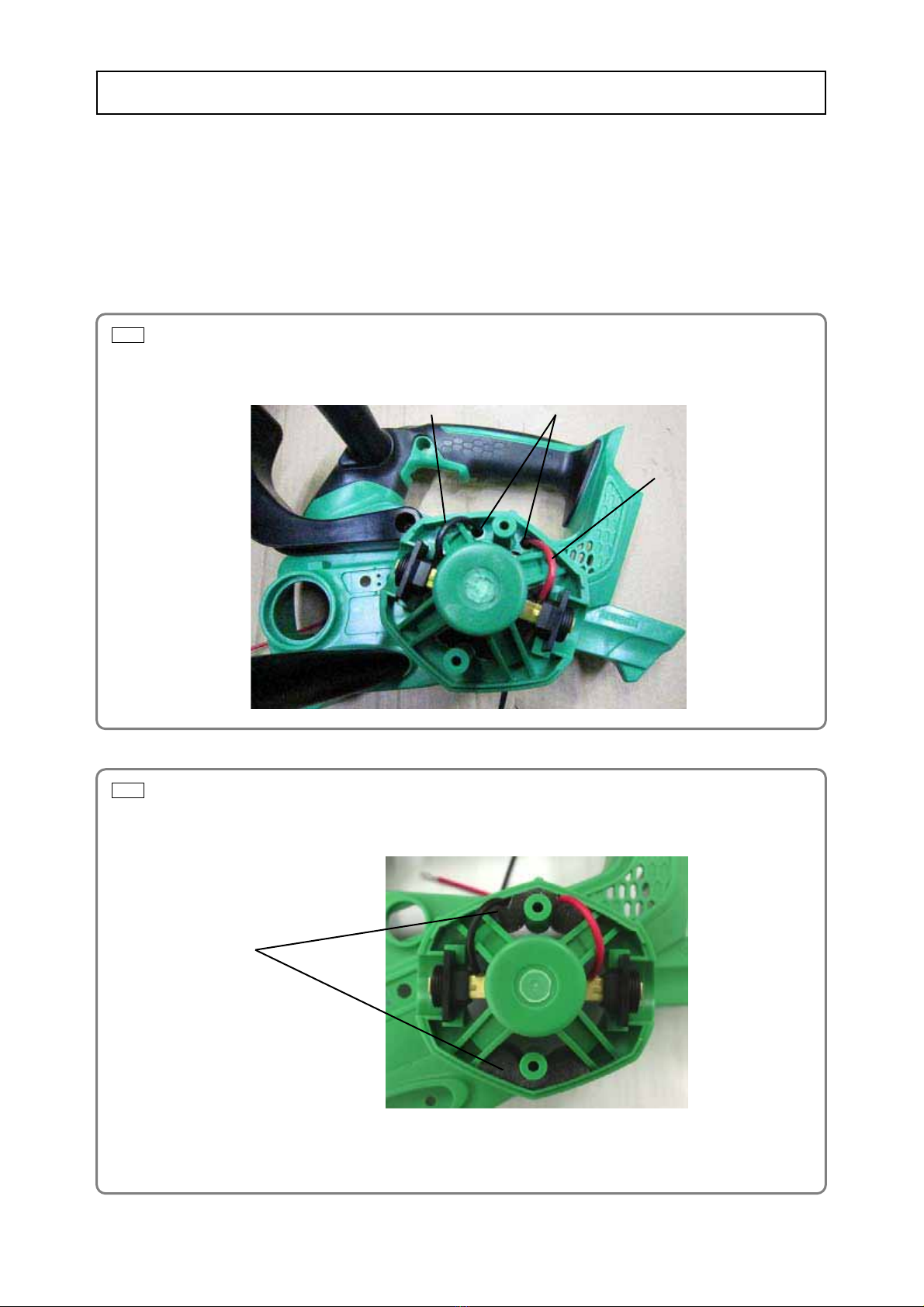
1. Removing the carbon brush
(1) Remove two Brush Caps [76] with a flat-blade screwdriver and remove the Carbon Brush [75].
(2) Do not apply excessive pressure to the Brush Holders [74] and [80] when removing the Carbon Brush
[75]. Otherwise, the Brush Holders [74] and [80] may be damaged.
2. Removing the saw chain and the chain bar
(1) Loosen the Knob [13] and remove the Chain Side Cover [17]. If necessary, rotate the Tension Dial [14]
counterclockwise slightly to reduce tension on the saw chain to facilitate this.
Then remove the Saw Chain (3/8 x 12") 91PX-45XJ [26] and the Chain Bar 12 inch 3/8 Sprocket PRC
[27] together.
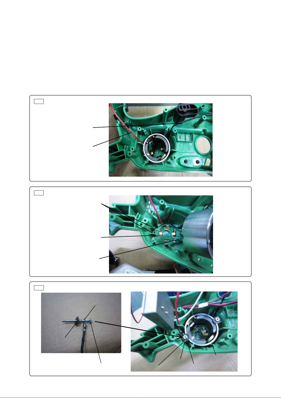
3. Removing the clutch housing
(1) Hold the sprocket of the Clutch Housing [12] in place with pliers. Loosen and remove the Lock Nut
(Left Hand) [9] by rotating it clockwise. Remove the Super Lock Washer M8 [10] and the Side Plate
[11]. Then remove the Clutch Housing [12].
4. Setting the brake handle to OFF
(1) Pull the Brake Handle [82] forward and set it to OFF position. The inner diameter of the Brake Band [5]
becomes smaller. This makes it easier to align during reassembly.
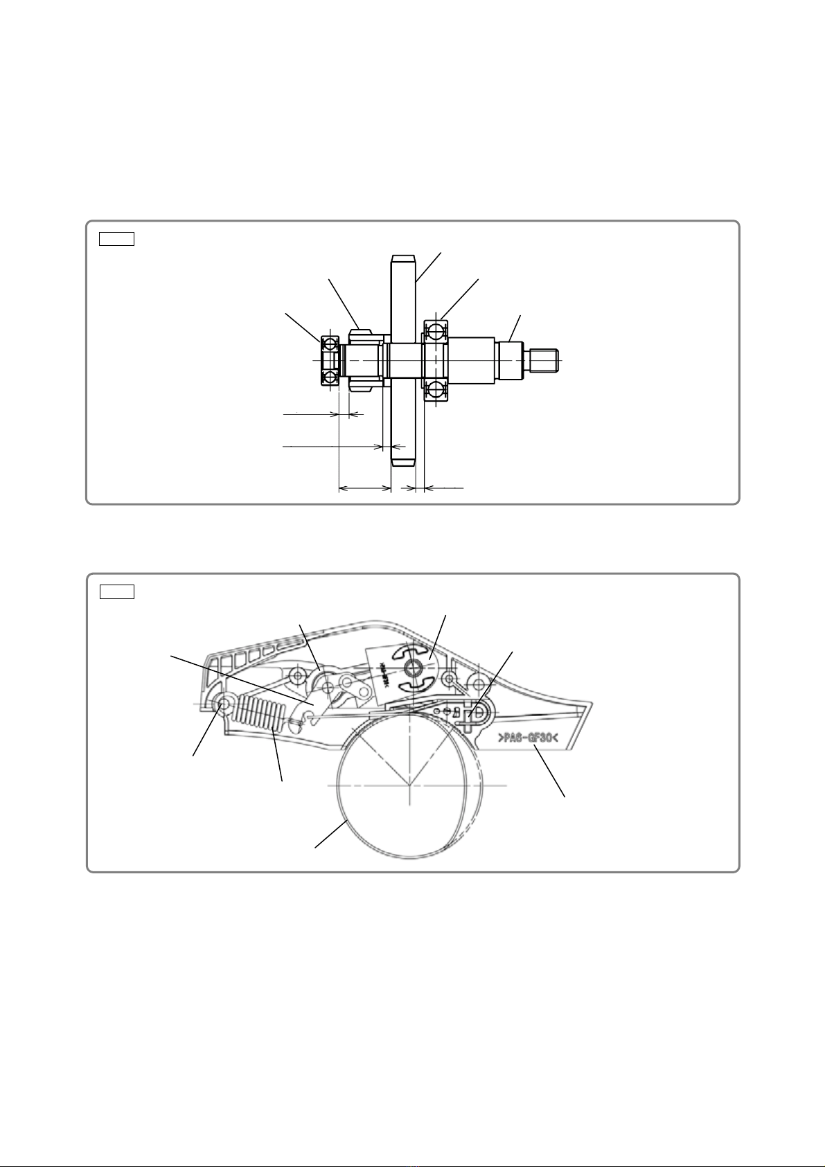
5. Disassembling the housing. handle cover set
(1) Remove eight Tapping Screws (W/Flange) D4 x 20 (Black) [29] and the Nozzle [46]. Then the Housing.
Handle Cover Set [32] can be removed with all internal parts stored inside it.
(2) Do not lose the Trigger [64], Spring [56] and Lock Button [57] when disassembling the Housing.
Handle Cover Set [32].
Disassembl
y
REPAIR GUIDE

-2-
6. Removing the inner cover
(1) Peel off the tape securing the Urethane Tube 95L [69] to the Oil Tank [70] and remove the Urethane
Tube 95L [69] from the Oil Tank [70].
(2) Remove the Tapping Screw (W/Flange) D4 x 20 (Black) [47] securing the Oil Pump [48] in place. Then
remove the Oil Pump [48].
(3) Remove four Tapping Screws (W/Flange) D4 x 20 (Black) [29] securing the Inner Cover [49] in place to
remove the Inner Cover [49].
(The Inner Cover [49] can be removed together with the Armature and Pinion Set [50] attached.)
7. Removing the magnet
(1) Remove two Hex Hd. Tapping Screws D4 x 45 [62] securing the Magnet [44] in place. Tap the end
surface of the housing with a wooden hammer to remove it.
8. Removing the front handle
(1) Remove four Tapping Screws (W/Flange) D4 x 20 (Black) [58] securing the Front Handle [81] in place
to remove the Front Handle [81] from the Housing. Handle Cover Set [32].
9. Removing the oil tank
(1) Remove the Tank Cap [79] from the Oil Tank [70] and then remove the Oil Tank [70].
10. Removing the brake handle
(1) Remove the Tapping Screw (W/Flange) D5 x 45 (Black) [83] securing the Brake Handle [82] in place to
remove the Brake Handle [82] and the Brake Lever [55].
11. Disassembling the power supply unit
(1) Cut the Connector 50092 [67] connection with nippers to remove the Brush Holders [74] and [80].
(2) Remove the solder from the internal wire connection with a soldering iron to disconnect the internal
wire from the Controller Terminal Set [54].
(3) Loosen and remove the screws to disconnect the internal wires from the two Switches [51].
12. Removing the brake link cover
(1) Remove three Tapping Screws (W/Flange) D4 x 20 (Black) [36] and remove the Brake Link Cover [1]
from the Housing. Handle Cover Set [32] together with the Brake Link [7], Brake Spring [8] and Brake
Band [5].
(2) Remove the Brake Spring [8] from the brake spring post and separate the unit into parts such as the
Brake Band [5] and the Brake Link [7]. At this time, do not lose the Needle Roller D3 [6].
13. Removing the chain side cover
(1) Insert a flat-blade screwdriver between the Tension Dial [14] (green) and the Chain Side Cover [17] and
rotate it slightly to remove the Tension Dial [14] and the Knob [13] together.

-3-
Fig. 1 ƔMounting the brush holders
Fig. 2 ƔSticking the sponges
Conduct reassembly by reversing the disassembly procedure, but note the following.
1. Mounting the brush holders
(1) Pass the internal wires of the Brush Holders [74] and [80] through the holes on the rear edge of the
housing as shown in Fig 1 paying attention to the polarity of the internal wires.
(2) Peel and stick the sponges to the specified locations as shown in Fig. 2.
Reassembl
y
Sponges
Pass through the holes.
Brush Holder [80] (Black)
Brush Holder [74] (Red)

-4-
Fig. 3 ƔMounting the magnet
Fig. 4
Fig. 5
2. Mounting the magnet
(1) Pass the internal wires of the Brush Holders [74] and [80] between the Magnet [44] and the Housing.
Handle Cover Set [32]. Ensure that they are not pinched (Fig. 3).
(2) Attach the Magnet [44] so that its concave portion correctly meshes with the protrusion on the Housing.
Handle Cover Set [32] (Fig. 4).
(3) When tightening the Hex Hd. Tapping Screw D4 x 45 [62], mount Washer (B) [63] so that the ribs of
the Housing. Handle Cover Set [32] are not deformed.
(4) Be sure to mount the thermistor at the tip of the internal wire when tightening the Hex Hd. Tapping
Screw D4 x 45 [62] (Fig. 5).
Protrusion on the Housing.
Handle Cover Set [32]
Concave portion of
the Magnet [44]
Ribs
Brush Holder [80] (Black)
Brush Holder [74] (Red)
Thermistor
Washer (B) [63]
Hex Hd. Tapping Screw D4 x 45 [62] Thermistor
Washer (B) [63]
Hex Hd. Tapping
Screw D4 x 45 [62]
Magnet [44]

-5-
Fig. 6 ƔMounting the oil pump
Fig. 7 ƔMounting the nozzle
3. Mounting the front handle
(1) Secure the Front Handle [81] to the Housing. Handle Cover Set [32] with four Tapping Screws
(W/Flange) D4 x 20 (Black) [58].
4. Mounting the oil pump
(1) Check that the needle pin D2.5 (included in the Inner Cover [49]) is mounted correctly.
(2) Check that the pump gear of the Oil Pump [48] can be rotated lightly at reassembly.
(3) Secure the Urethane Tube 95L [69] to the Oil Tank [70] with adhesive cellophane tape. (Before
adhering cellophane tape, wipe oil off the surface of the Oil Tank [70].)
(4) Insert the hole side of the Nozzle [46] into the Housing. Handle Cover Set [32] aligning the Nozzle [46]
parallel to the ridge line (stepped portion) of the Housing. Handle Cover Set [32].
* Pay attention to the orientation of
the Nozzle [46].
• Insert the hole side of the Nozzle
[46] into the Housing. Handle
Cover Set [32].
• Align the Nozzle [46] parallel to
the ridge line of the Housing.
Handle Cover Set [32].
Oil Pipe [61]
Oil Tank [70]
Secure in place with
adhesive cellophane tape.
Inner Cover [49] Oil Pump [48]
Urethane Tube 95L [69]
Urethane Tube 130L [45]
Oil Pipe [61]
Nozzle [46]
Urethane Tube 130L [45]
Housing. Handle Cover Set [32]
Ridge line
(stepped portion)

-6-
Fig. 9 ƔWiring diagram
Internal wire (brown)
Internal wire
(brown)
Switch [51]
Noise
suppressor
Internal wire
(
red
)
Internal wire (white)
Controller
Terminal Set [54]
Connector 50092 [67]
Connector
50092 [67]
Switch [51]
Switch Lever [60]
Brake Lever [55]
5. Wire connection of the power supply unit
(1) Be sure to perform wire connection in accordance with the connecting diagram. Pay attention to colors
of the internal wires and the terminals to be soldered.
(2) When connecting the internal wires to the two Switches [51], insert the cores of the internal wires into
the terminal holes as far as they will go and then secure them with screws. Check that the internal
wires cannot be pulled out by force of 200 g after connection.
(3) Be careful of the polarity of the Diode [68] when mounting.
Thermistor
Fig. 8 ƔConnecting diagram
Connector
50092 [67]
Battery terminal
Switch [51]
Internal wire (white)
Internal wire (red)
Brush Holder [74] (Red)
Brush Holder [80] (Black)
Internal Wire (Red) L490 [53]
Noise
suppressor
Switch [51]
LED light
Internal wire (black)
Controller Terminal Set [54]
Diode [68]
Internal Wire (Brown) L165 [65]
Internal Wire (Red) L240 [52]
Internal Wire (Black) L120 [66]
Connector 50092 [67] Tact switch

-7-
6. Mounting the spindle and the gear
(1) Mount the Gear [40] to the Spindle [37] in accordance with the dimensions shown in Fig. 10.
(2) Mount the above assembly of the Gear [40] and the Spindle [37] to the Inner Cover [49] being careful
not to damage the tooth flank of the pump gear in the Oil Pump [48].
(3) Insert the Oil Pipe [61] and the Urethane Tube 130L [45] into the pump at two locations.
(4) Apply grease (Shell Alvania RL3) to the tooth flank of the Gear [40].
7. Mounting the parts inside the brake link cover
(1) Mount the parts inside the Brake Link Cover [1] as shown in Fig. 11.
8. Mounting the housing. handle cover set
(1) Mount the Lock Button [57], Spring [56], Rubber Cushion [33] and Hook [34] to their correct locations.
Insert the Nozzle [46] coming from the Oil Pump [48] into the spout of the Housing. Handle Cover Set
[32] and mount the handle cover of the Housing. Handle Cover Set [32]. Check that the internal wires
do not sag or are not pinched.
(2) Check that the Brake Lever [55] of the Brake Handle [82] is not detached from the Switch Lever [60].
(3) Check that the Brake Lever [55] meshes with the Brake Link Holder [4].
(4) Apply grease (Shell Alvania RL3) to the Link Sleeve [35] and mount it to the Brake Link Holder [4].
Fig. 11 ƔMounting the parts inside the brake link cover
Brake spring post
Brake Spring [8]
Brake Band [5]
Brake Link Cover [1]
Needle Roller D3 [6]
Brake Link Holder [4]
Brake Link [7]
Brake Support Plate [2]
Fig. 10 ƔMounting the spindle and the gear Gear [40]
Ball Bearing 6001VVCMPS2L [38]
Ball Bearing 606VVC2 [42] Spindle [37]
Worm [41]
3.5±0.1
(2.8±0.1)
18±0.1 (3)

-8-
ƔPinion of the Armature and Pinion Set [50]: 2 g of Shell Alvania Grease RL3
ƔTooth flank of the Gear [40]: 5 g of Shell Alvania Grease RL3
ƔSliding portions of the Brake Link [7], Brake Link Holder [4] and Brake Support Plate [2]: 0.5 g of Shell
Alvania Grease RL3
ƔOuter circumference of the Brake Link Holder [4] and the sliding portion at the inner circumference of
the Brake Link Holder [4] insertion hole on the Housing. Handle Cover Set [32]: 0.5 g of Shell Alvania
Grease RL3
ƔTapping Screws D3 [19] [20] ······································································· 0.5 to 0.7 N•m {5 to 7 kgf•cm}
ƔTapping Screws (W/Flange) D4 x 20 (Black) [29] [36] [47] [58] ··············· 2.1 to 3.0 N•m {20 to 30 kgf•cm}
ƔHex. Hd. Tapping Screw D4 x 45 [62] ························································· 2.1 to 3.0 N•m {20 to 30 kgf•cm}
ƔTapping Screw (W/Flange) D5 x 45 [83] ····················································· 2.9±0.5 N•m {30±5 kgf•cm}
ƔLock Nut (Left Hand) M8 [9]········································································· 8.0±1.0 N•m {80±10 kgf•cm}
ƔCheck that the chain oil discharges properly (operating time: 1 to 3 minutes).
ƔCheck that the LED lights and the remaining battery indicator lamp lights properly.
The remaining battery level can be checked by pressing the remaining battery indicator switch. The table
below shows the status of remaining battery indicator lamp and battery remaining power.
Indicator
status Remaining battery level
Sufficient battery remains.
(Approximately 68% or more)
Battery half-empty.
(Approximately 34% to 67%)
Battery very low.
(Approximately 33% or lower)
Recharge as soon as possible.
ƔCheck that the Brake Handle [82] can be operated properly and the brake can be applied.
2. Precautions on disassembly and reassembly of battery charger
Refer to the Service Manual for precautions on disassembly and reassembly of the Model UC 36YRSL
Battery Charger.
Checkin
g
after reassembl
y
Lubrication
Screw ti
g
htenin
g
tor
q
ue

-9-
MODEL Variable
Fixed 10 20 30 40 50 60 min.
CS 36DL
General assembly
Inner Cover
Clutch
Housing
Spindle
Ball Bearing
(6001VVCM)
Gear
Worm
Ball Bearing
(606VVC2)
Oil Pump
Armature and
Pinion Set
Trigger
Switch x 2
Oil Tank
Tank Cap
Brake Handle
Brake Lever
Housing.
Handle
Cover Set
Magnet
Work Flow
Brake Link
Cover
Brake Support
Plate
Brake Lever
Spring
Brake Link
Holder
Brake Band
Brake Link
Brake Spring
Chain Bar
Saw Chain
(3/8 x 12”)
Knob
Tension Dial
Tension Gear
Chain Side
Cover
Chain Puller
Guide Plate
STANDARD REPAIR TIME
(
UNIT
)
SCHEDULES

Model CS 36DL
CORDLESS CHAIN SAW
LIST NO. J842
2013·1·25
(E1)
A
A
1
2
3
4
5
6
7
8
9
10
11
12
13
14
15
16
17
19
20
22
24
25
26
27
30 32
33
31
28
29
29
36
37
38
39
40
41
42
46
47
48
49
50
43
44
51
51
64
58
67
52
54
55
56
57
58
59 60
62
63
69
70
81 82 83
79
76 75 80
77
29
34
58
45
61
75 76
74
18
71
21
23
35
78
68
53
66
65
72
84
73
29
501
502
503
504

PART
S
CS 36DL
DESCRIPTION REMARKS
1 335-134 BRAKE LINK COVER 1
2 669-6782 BRAKE SUPPORT PLATE 1
3 669-6783 BRAKE LEVER SPRING 1
4 335-135 BRAKE LINK HOLDER 1
5 669-9013 BRAKE BAND 1
6 668-5391 NEEDLE ROLLER D3 1
7 668-5388 BRAKE LINK 1
8 668-5389 BRAKE SPRING 1
9 335-192 LOCK NUT (LEFT HAND) M8 1
10 957-042 SUPER LOCK WASHER M8 1
11 335-139 SIDE PLATE 1
12 668-5403 CLUTCH HOUSING 1
13 335-151 KNOB 1
14 335-150 TENSION DIAL 1
15 315-500 MACHINE SCREW (W/WASHER) M4 X 8 (BLACK) 1
16 335-152 TENSION GEAR 1
17 335-149 CHAIN SIDE COVER 1
18 335-156 BEVEL GEAR (A) 1
19 696-352 TAPPING SCREW D3 1
20 334-333 TAPPING SCREW D3 X 12 (BLACK) 1
21 335-688 DUST SHEET 1
22 939-543 RETAINING RING FOR D14 SHAFT (10 PCS.) 1
23 996-407 O-RING (1AP-12) 1
24 335-153 CHAIN PULLER 1
25 335-154 GUIDE PLATE 1
26 669-7852 SAW CHAIN (3/8 X 12") 91PX-45XJ 1
27 669-6990 CHAIN BAR 12 INCH 3/8 SPROCKET PRC 1
28 335-142 SPIKE 1
29 301-653 TAPPING SCREW (W/FLANGE) D4 X 20 (BLACK) 16
30 335-155 CHAIN CATCHER 1
*31 334-998 BATTERY BSL 3620 (EUROPE, AUS, NZL) 1
*31 334-997 BATTERY BSL 3620 (USA, CAN) 1
32 335-129 HOUSING. HANDLE COVER SET 1
33 332-668 RUBBER CUSHION 1
34 669-8696 HOOK 1
35 335-690 LINK SLEEVE 1
36 301-653 TAPPING SCREW (W/FLANGE) D4 X 20 (BLACK) 3
37 335-137 SPINDLE 1
38 600-1VV BALL BEARING 6001VVCMPS2L 1
39 939-542 RETAINING RING FOR D12 SHAFT (10 PCS.) 1
40 335-138 GEAR 1
41 669-6886 WORM 1
42 606-ZZM BALL BEARING 606VVC2 1
43 335-140 FAN GUIDE 1
44 323-156 MAGNET 1
45 335-148 URETHANE TUBE 130L 1
46 335-147 NOZZLE 1
47 301-653 TAPPING SCREW (W/FLANGE) D4 X 20 (BLACK) 1
48 669-6887 OIL PUMP 1
49 335-136 INNER COVER 1
- 2 - 1 - 13
*ALTERNATIVE PARTS
ITEM
NO. NO.
USED
CODE NO.
ITEM
NO. NO.
USED
CODE NO.

CS 36DL
DESCRIPTION REMARKS
50 360-948 ARMATURE AND PINION SET 1
51 335-124 SWITCH 2
52 335-687 INTERNAL WIRE (RED) L240 1
53 335-694 INTERNAL WIRE (RED) L490 1
54 335-128 CONTROLLER TERMINAL SET 1
55 335-132 BRAKE LEVER 1
56 314-429 SPRING 1
57 331-682 LOCK BUTTON 1
58 301-653 TAPPING SCREW (W/FLANGE) D4 X 20 (BLACK) 5
59 962-569 WASHER (B) 1
60 335-133 SWITCH LEVER 1
61 335-146 OIL PIPE 1
62 981-824 HEX. HD. TAPPING SCREW D4 X 45 2
63 319-956 WASHER (B) 2
64 335-125 TRIGGER 1
65 335-695 INTERNAL WIRE (BROWN) L165 1
66 335-696 INTERNAL WIRE (BLACK) L120 1
67 959-141 CONNECTOR 50092 (10 PCS.) 1
68 335-689 DIODE 1
69 335-145 URETHANE TUBE 95L 1
70 335-143 OIL TANK 1
71 NAME PLATE 1
72 335-692 CAUTION LABEL (EX) 1
73 335-697 PANEL SHEET 1
* 74 335-127 BRUSH HOLDER 1
* 74 335-699 BRUSH HOLDER 1 FOR EUROPE
75 999-068 CARBON BRUSH (1 PAIR) 2
76 319-847 BRUSH CAP 2
77 335-141 TAIL COVER 1
78 335-691 TANK CAP PACKING 1
79 335-144 TANK CAP 1
* 80 335-126 BRUSH HOLDER 1
* 80 335-698 BRUSH HOLDER 1 FOR EUROPE
81 335-130 FRONT HANDLE 1
82 335-131 BRAKE HANDLE 1
83 316-321 TAPPING SCREW (W/FLANGE) D5 X 45 1
84 334-379 FERRITE CORE 2
1 - 13 - 3 -
*ALTERNATIVE PARTS
PARTS
NO.
USED
CODE NO.
ITEM
NO.

CS 36DL
DESCRIPTION REMARKS
501 669-9116 CHAIN COVER 1
502 669-8688 FILE 5/32 SET 1
503 957-681 LUBRICANT OILER (120 CC) 1
504 CHARGER (MODEL UC 36YRSL) 1
- 4 - Printed in Japan 1 - 13
(130125N)
*ALTERNATIVE PARTS
STANDARD ACCESSORIES
NO.
USED
CODE NO.
ITEM
NO.
Table of contents