HobbyPCB IQ32 User manual

IQ32 SDR Transceiver
Operations Manual
IQ32 SDR Transceiver
Operations Manual

Table of Contents
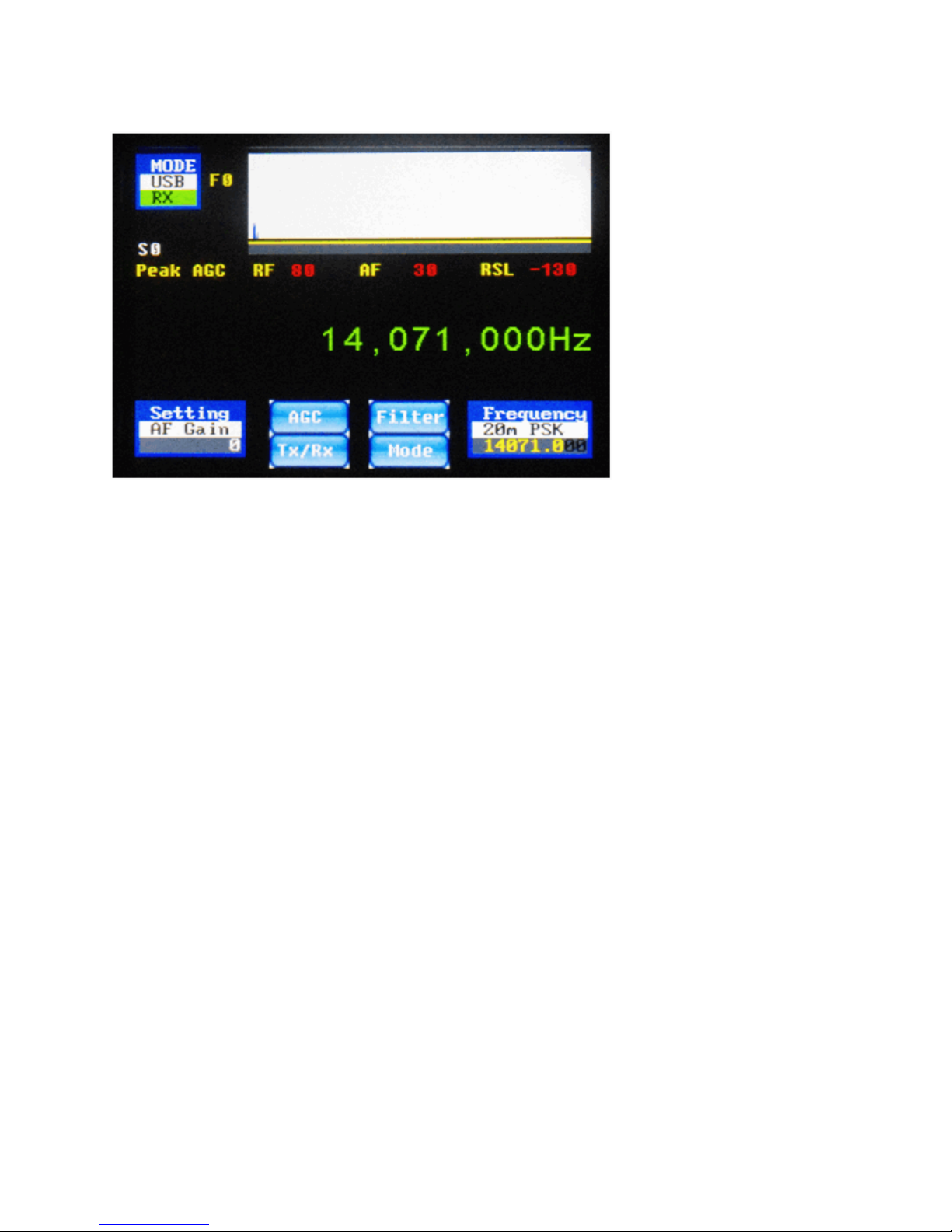
Basic Navigation......................................................................................................................................... 4
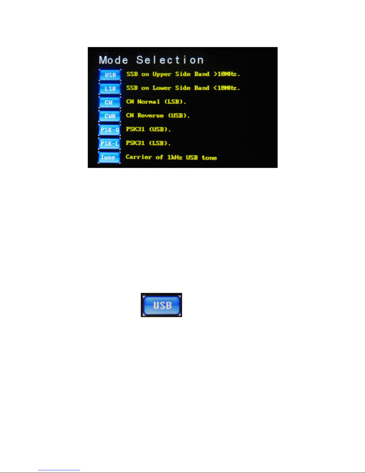
Mode Selection ....................................................................................................................................... 5
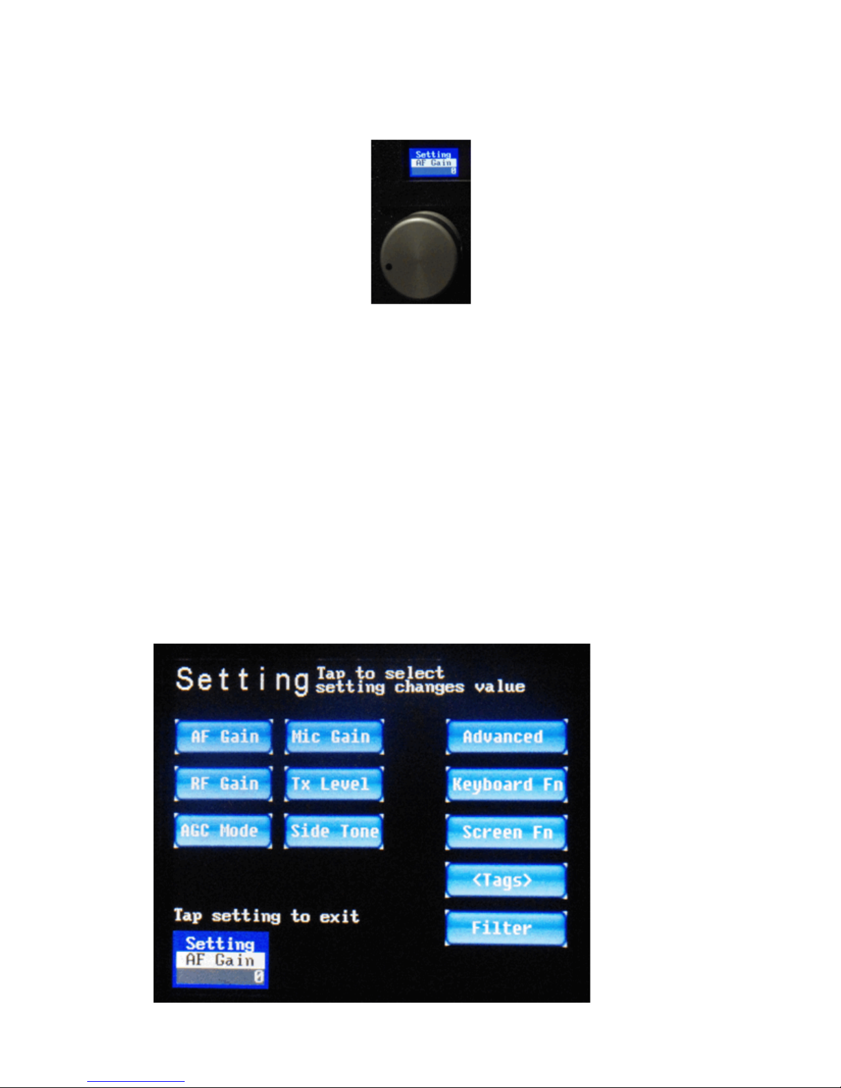
Settings Screens ...................................................................................................................................... 8
Main Settings ...................................................................................................................................... 9
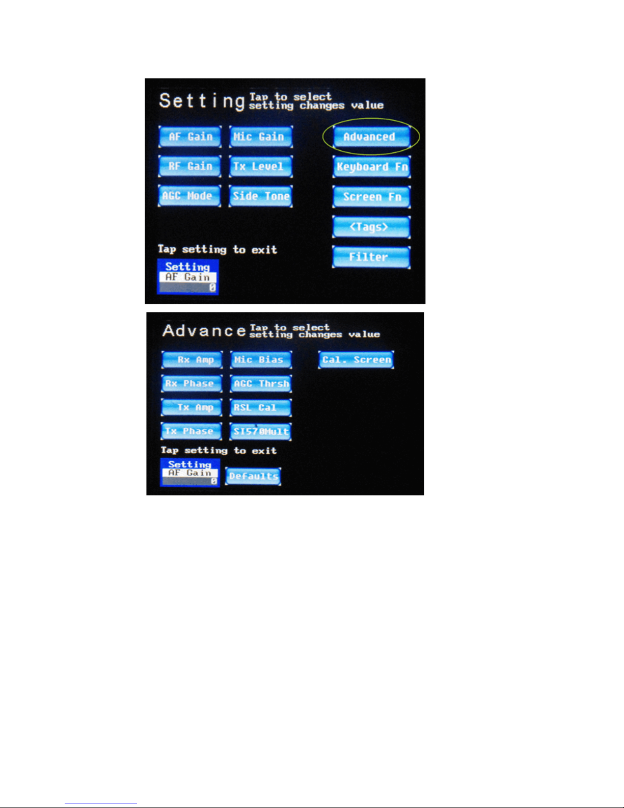
Advanced Settings ............................................................................................................................ 10
Keyboard Fn Settings........................................................................................................................ 12
Screen Fn Settings............................................................................................................................. 22
<Tags> (PSK Macro) Settings .......................................................................................................... 30
Bandpass Filter Settings.................................................................................................................... 35
Frequency Manager Screen................................................................................................................... 37
Receive Filter Settings .......................................................................................................................... 41
CW Operation ........................................................................................................................................... 42
SSB Operation .......................................................................................................................................... 47
PSK Operation .......................................................................................................................................... 50
AGC Modes Explained ............................................................................................................................. 58
Mode 0 .................................................................................................................................................. 58
Mode 1 .................................................................................................................................................. 58
Mode 2 .................................................................................................................................................. 58
Mode 3 .................................................................................................................................................. 58
PSK Cheat Sheet ....................................................................................................................................... 59
F1: Call CQ........................................................................................................................................... 59
F2: Send Your Name and QTH ............................................................................................................. 59
F3: Send your Rig information ............................................................................................................. 59
F4: Send your Antenna information...................................................................................................... 59
F5: Confirm Called Station Name and Callsign, and send Back to You (BTU)................................... 59
F6: Send Thank You and Best Wishes (73's) ........................................................................................ 59
F7: (Changes to USB mode) ................................................................................................................. 59
F8: (Changes to LSB mode) ................................................................................................................. 59
F9: (Changes to CW mode) .................................................................................................................. 59
F10: Toggles Transmitter Between Receive and Transmit Mode ......................................................... 59
F11: Clear Transmit Buffer ................................................................................................................... 59
F12: _________________________________________________________________ .................... 59

Radio Setup............................................................................................................................................... 60
Appendix – Tags, Functions, Buttons, and Keyboard............................................................................... 61
Tags ....................................................................................................................................................... 61
Functions............................................................................................................................................... 62
Default On-Screen Button Functions.................................................................................................... 62
SSB Operational Screens Buttons..................................................................................................... 62
CW Operational Screens Buttons ..................................................................................................... 63
PSK Operational Screens Buttons ** ............................................................................................... 63
Keyboard Function Keys ...................................................................................................................... 63

Basic Navigation
Thank you for purchasing a HobbyPCB IQ32 transceiver, connect a suitable antenna or dum-
my load and a power supply. Remember, you are responsible for the radio, and you must en-
sure that any emissions are on a proper frequency (one for which you are properly licensed
and allowed to transmit).
Turn on the power, and you should see the splash screen as depicted below in Figure 1. It an-
nounces the version of the software you are running. This picture shows the current version at
the time of preparation of this document. We expect the software will continue to evolve, and it
is always possible (actually, probable) that there has been an update to the firmware that
snuck out (sneaked out?) into the open in between updates to the documentation.
You can go to http://www.hobbypcb.com/iq32 to check for firmware updates
Figure 1: Sign-On (“Splash”) Screen

After a few seconds, you should see the screen shown below (Figure 4). It’s the home screen.
From here you can start your journey, and at each subsequent power-up, you will be returned
here after the “splash screen” is briefly displayed.
The software has multiple screens that are accessed by pressing the appropriate place on the
touchscreen. These icons are multifunction. The top line indicates the name of the icon, what
secondary screen or function it selects, what option is currently selected and the value of the
option. These are all in a touch sensitive area on the screen.
Mode Selection
So, for example, Figure 5 (above) is called the Mode icon or Mode widget. Pressing it will bring
you to the mode selection screen. The current mode is PSK-U (PSK in USB) and we are cur-
rently in Receive (RX). If you touch the Mode icon (upper left corner of the screen) you will
switch to the Mode selection screen (Figure 6, depicted below).
Figure 4: Home Screen (PSK Operation)
Figure
5: Mode Icon

On the mode selection screen, you can select the operating mode you desire, by touching the
appropriate on-screen button, and it will switch to that mode and the mode’s operating screen.
If you selected the wrong one, you just have to hit the mode button (Figure 5) on that screen to
return to the mode selection screen, and re-select the desired one. Later in the document I will
give you more details on the selections but they should be pretty self-explanatory already.
One new button on this screen is the “Tune” button which sends out a 1 Khz carrier so you can
set the power level or tune your transmitter to your antenna, when the IQ32 is connected to the
HobbyPCB Hardrock-50 power amplifier
Press the USB icon (Figure 7) and go to the USB Screen (Figure 8).
Once on the USB screen, (or for that matter, any operational screen), you can either operate
the radio, access the Frequency Manager, or access the Settings screen. The frequency of
operation is now displayed in big green digits between the DSP window (waterfall or spectrum
display) and the widgets/buttons on the bottom third of the screen. This is true for not only the
USB screen as shown in Figure 8, but also on the LSB screen, the CW screen, and the CWR
screen. Unfortunately, there was not enough room on the PSK screens to add the large fre-
quency numbers. But in all cases, the widget in the bottom right corner does show the fre-
quency to which you are tuned. There are also 4 buttons on the CW and SSB screens, and 2
buttons on the PSK screens, which are shortcuts to other functions, to be described later in
this manual.
Figure 6: Mode Selection Screen
Figure 7: USB Icon

For now, let's explore the Setting icon, which is visible on any of the operations screens, and
also on the Setting screens themselves. Like the Mode icon, it is both a status indicator and a
touch region. The top of the icon reminds you of its function (Setting). The middle portion tells
you which Setting is selected. The lower portion displays the current value of the selected Set-
ting. In Figures 8 (above) and 9 (below), the AF Gain Setting is selected, and its current setting
is 0. You can adjust the value of the currently displayed setting with the left-hand rotary encod-
er, increasing the value by rotating it clockwise or decreasing the value by rotating it counter-
clockwise.
We'll now go through the many settings in some detail.
Figure 8: USB Operation Screen

Settings Screens
From any operational screen, touching the Setting widget (as in Figure 9 above), will bring you
into the setup and adjustments screens. The first such screen is shown in Figure 10, below.
There are six buttons on the left side which go directly to settings whose values you can set
with the left rotary encoder. The five buttons on the right take you to sub-menus of the Settings
menu for the functions that you will not need to change nearly as often.With those six most
common settings, the rotation of the left-hand rotary encoder causes the value to change im-
mediately (and the numeric value of the option to be displayed in the middle part of the option
button/status widget).. You don't need to press any other button or do anything else for the ad-
justment to take effect. When you tap the on-screen Setting button again, this screen is exited,
and you return to the previous screen. The setting item you most recently selected remains in
the bottom left corner of the operation screen, and you can continue to adjust its value with the
left-hand rotary encoder knob, even after you return to an operation (SSB/CW/PSK) screen.
Figure 9: Setting Widget Above the Left Rotary
Figure 10: Main Settings Menu Page

Main Settings
The first six settings are as follows:
•AF Gain: Volume control, adjusts the audio level of the headphone jack. Range is -127
to +48
•RF Gain: Increase for weak signals, and decrease for strong signals. Range is 0 to +80.
If you have AGC enabled, leave it at 80.
•AGC Mode: Selects Peak AGC (mode 0), Digital AGC (mode 1), SSB AGC (mode 2), or
AGC Off (mode 3). The AGC mode affects both how the AGC works and how the S-meter dis-
play value is calculated. See the AGC section for more details on this.
•Mic Gain: Adjusts the I/Q levels to the transmitter in SSB mode. Adjust for maximum
level on the Spectrum view (to be described below) without causing any distortion of the signal.
Range is 0 to 80, default is 20. A 50 mV input gives maximum output with a setting of 20 or 1
volt peak-to-peak.
•Tx Level: In CW and PSK modes, this control adjusts the level of the I/Q signal to the
transmitter. Adjust this control for maximum modulation without distortion. Range is 0 to 29.
Maximum is 1 volt peak-to-peak.
•Side Tone: Side tone level, adjusts the level of the side tone present in the headphones
during CW transmit. Adjust to the desired level. Range is -6 to +29.
There are five other sub-menus that are accessed from this Settings screen:
•Advanced: Advanced settings that less frequently need to be adjusted.
•Keyboard Fn: Program in the actions of the Function keys (F1 to F12) on the attached
keyboard. This is a new feature that was not present in the older v1.052 firmware.
•Screen Fn: Program in the functions of certain on-screen buttons. This is also a new
feature that was not present in the v1.052 firmware.
•<Tags>: Program in the values of strings such as the PSK mode transmission strings,
which are associated with a particular “tag name”. In the older v1.052 firmware, this button
used to be called “Functions”.
•Filter: Set up bandpass filters that are automatically switched into place as you change
frequency. (The bandpass filters are not a part of the IQ32; they must be obtained separately
and integrated by you into the product. This menu simply assists you in configuring the radio to
the external bandpass filter system of your choice so that it can operate as automatically as
possible. This menu sets the values of the three output bits on the BPF connector for various
ranges of operational frequencies, and it is assumed that the bits that are output select the
proper bandpass filter.)
We will look at these five other buttons in some more detail shortly. But first, let's look over the
Advanced Settings menu more closely.

Advanced Settings
On the main Settings screen (top half of Figure 11, below), if you tap on the Advanced button,
you will be brought to the Advanced Settings screen (bottom half of Figure 11, below). Like
before, the most often-used Advanced settings each have a button, which you tap, and then
you adjust its value with the left rotary encoder. Again, the changes you make with the rotary
encoder take effect immediately.
The Advanced menu (bottom half of Figure 11) contains a number of settings that were for-
merly contained on (the very cluttered) “Options” screen several firmware releases ago. These
settings typically need to be set only once, or at most, only occasionally, such as if you change
to a different microphone, or install a different RF front end.
Figure 11: Advanced Settings Screen

The Settings available on the Advanced Settings menu are as follows:
•Rx Amp: This is the adjustment of the I/Q amplifier's voltage gain. This must be adjust-
ed to maximize the suppression of the unwanted sideband. See the Adjustment section for
more details. Range is 1,000 to 10,000.
•Rx Phase: This is the adjustment of the I/Q amplifier's phase gain. This must be adjust-
ed to maximize the suppression of the unwanted sideband. See the Adjustment section for
more details. Range is -10,000 to +10,000.
•Tx Amp: This is the adjustment of the I/Q amplifier's voltage gain. This must be adjust-
ed to maximize suppression of the unwanted sideband. See the Adjustment section for more
details. Range is 1,000 to 10,000.
•Tx Phase: This is the adjustment of the I/Q amplifier's phase gain. This must be adjust-
ed to maximize suppression of the unwanted sideband. See the Adjustment section for more
details. Range is -10,000 to +10,000.
•Mic Bias: This is either on (1) or off (0). If you are using an electret microphone you
need this bias voltage to allow the microphone to work.
•AGC Thrsh: Adjusts the AGC Threshold, i.e., the point where AGC starts to function.
Default value is 400 for normal operation. Range is 50 to 1000. See AGC section for more de-
tails.
•RSL Cal: Adjust this to calibrate your S Meter. See the Adjustment section for more de-
tails.
•SI570Mult: Not used in the IQ32.
There are two other buttons of note on the Advanced Settings screen:
•Cal Screen: Use this button to calibrate the touchscreen if your taps are not activating
the options you are trying to activate. This will bring you back to the screen calibration screens
that you initially saw the very first time you turned on your system. As previously noted, if the
calibration is sufficiently far out of whack, you won't be able to select this option by touching
the screen. In that case, power down the IQ32, power it back up again, and promptly (and
simultaneously) press both of the rotary encoders inwards. This selects the same calibration
screens.
•Defaults: Use this button if you mess up these settings so badly that the radio is not
operational, and you need to get everything set back to sensible values.
There are four other Settings screens that we need to cover, one of which first appeared in
v1.052 of the firmware and two of which are brand new for release 1.059 of the firmware (not
widely released) and later. We'll discuss all four of them now.

Keyboard Fn Settings
If you are currently on one of the operational screens, tap on the Settings icon again to bring
up the Main Settings screen (top part of Figure 12, below) like before. This time, however, in-
stead of tapping on Advanced, tap on the Keyboard Fn button on the right side of the screen,
which brings up the screen shown in the bottom part of Figure 12..
The standard keyboard attached to your IQ32 system has 12 “function” keys across the top
row. Typically, application programs can interpret these 12 keys any way that they choose to.
Figure 12: Setting →KeyboardFn Screen

The IQ32 firmware is no exception to this, and like many (but certainly not all) PC application
programs, you can adjust how these function keys do what they do within the program.
From the Setting screen, touch the on-screen KeyboardFn button to get to the second screen
shown in the lower half of Figure 12, above.
From this screen, you can touch any of the on-screen buttons grouped in the top left corner of
the screen, numbered 1 – 12, which correspond to the twelve
F1
through
F12
keyboard but-
tons and adjust the function that it performs.
By default, the twelve function keys are dedicated to the following actions:
•
F1
Transmit your callsign (PSK mode only)
•
F2
Transmit your name and location (PSK mode only)
•
F3
Transmit information about your rig (PSK mode only)
•
F4
Transmit information about your antenna (PSK mode only)
•
F5
Transmit “back to you” message (PSK mode only)
•
F6
Transmit “Thank You” message (PSK mode only)
•
F7
Switch to USB mode with a single tap
•
F8
Switch to LSB mode with a single tap
•
F9
Switch to CW mode with a single tap
•
F10
Toggle between Receive Mode and Transmit Mode
•
F11
Clear out the PSK conversation window
•
F12
(Currently not in use.)
To control exactly how these keyboard function keys act, tap on the corresponding button on
the screen. You will then be able to use your keyboard to modify the action of the key, within
certain limits. Let's look at them one-by-one.
Tap on the on-screen button #1 named “1 Call”. This will produce a display as shown below, in
Figure 13:

As seen above (in Figure 13), pressing the
F1
function key while in PSK mode will turn on the
transmitter (with the <Tx> operator, see Appendix 1), send out CQ (“seek you”) three times,
then send “de” (French and typical CW/PSK abbreviation for “from”), then send out your Ama-
teur Radio Callsign (with the <MyCall> tag, see the <Tags> section below), then send out the
abbreviation for “please” (“pse”) and three copies of the abbreviation for “OK” (“k k k”). The
IQ32 is then switched to receive mode (with the <Rx> operator, see Appendix 1). Note that
there is room for up to two lines of text/commands/tags on the screen, and the cursor (the ^
character) is shown below the second line of the editing buffer. You should also note that with
firmware release v1.059 and later, the editing of these strings is a lot less primitive than it was
in earlier versions of the firmware. You can now use the
LEFT ARROW ()
or
RIGHT AR-
ROW ()
keys to move the cursor into the middle of a string, and then add or delete text.
The
TAB (|)
key switches between editing of the string and the key's label. The
UP AR-
ROW ()
and
DOWN ARROW ()
keys allow you to switch to a different item to be edited.
Also, holding a key down will cause it to start repeating, after a brief delay.
For example, you could position the cursor and remove one of the three CQ's or insert a fourth
CQ. In the past, if you wanted to make such a change at the CQ's near the beginning of the
string, it was necessary to use the
BACKSPACE
key to delete everything to the right of your
desired edit point, make your change, and then re-type anything that you were forced to delete
but really wanted to keep. No more!
Once you have configured the operation of the
F1
function key as desired, tap on the Done
button to return to the current operating screen.
Figure 13: Function Key F1 Setting Screen

Note that you can also tap on the Tags button to switch to editing of the values of the internal-
ly-stored tags. This is a shortcut, so that you don't have to tap on Settings then Advanced
Settings and then <Tags>. The <Tags> will be described in more detail shortly.
In a similar manner, you can fine-tune the actions performed by the
F2
through
F12
keyboard
function keys. Let's run through the default programming of those keyboard function keys, one
at a time.
From the Keyboard Fn Settings screen, tap on the on-screen button #2, which is labeled “2
Name”. Keyboard button
F2
is used in PSK31 mode to send your name and your location
(QTH) to the station you are working. You should see something like Figure 14, below, after
tapping on the second on-screen button.
As you can see, the standard firmware comes programmed to send the string “My name is “,
followed by your name (as stored in a <Tag> called <MyName>), followed by the string “and
my QTH is”, followed by your operating location (as stored in a <Tag> called <QTH>).
There is a Done screen button that you use when you are done editing this keyboard function,
and a Tags button which is a shortcut to the editing of the <Tags> strings.
Keyboard function key
F3
is used while in PSK mode when you want to send information
about your rig . If you pick this button, you will see something like Figure 15, below:
Figure 14: Function Key F2 Setting Screen

As you can see in Figure 15 above, the default action of this key is to send the string “My rig is
an” followed by the string programmed into the <Tag> which is named <Rig>.
Keyboard function key
F4
is set up to send information about your antenna when you are in
PSK31 mode. If you tap on this on-screen button, you will see something like Figure 16, below:
As you can see, the default action is to send the string “My ant is a” followed by the string
which has been programmed into the <Tag> named <Ant>.
Keyboard function key
F5
is used near the end of a PSK-31 QSO. The label on the screen for
function key
F5
is “BTU” which is short for “Back to You”. You can see this if you select the
fifth button from the Keyboard Fn menu, after which you should see something like Figure 17,
below. In total, the default action of the
F5
function key is to transmit “Well “, then the name of
the station with whom you are conversing (in the <Tag> called <StnNM>), followed by “,
Figure 15: Function Key F3 Setting Screen
Figure 16: Function Key F4 Setting Screen

BTU” (Back To You) followed by the callsign of the station with whom you are conversing,
(from the <StnCS> tag) followed by “de” (from) followed by your callsign (stored in the
<MyCall> tag) followed by “kn”, after which the radio is switched to receive mode with the
<Rx> macro. Examine Figure 17, below, to see all of these programming details.
Keyboard function key
F6
is used to send your “Thank You” at the end of a PSK-31 QSO. You
can customize this by tapping on the sixth on-screen button, which should bring up a setting
screen similar to Figure 18, below:
The string stored in this location and transmitted when you press keyboard function key
F6
, by
default, is shown above as TNX (“thanks”) for the PSK31 QSO. (conversation). 73's (Best
wishes).
Figure 17: Function Key F5 Setting Screen
Figure 18: Function Key F6 Setting Screen

The response to keyboard function key
F7
is programmed by default to change the IQ32 to
USB (Upper Side Band) mode, as can be seen in Figure 19, below. Note that this is accom-
plished by issuing the <USB> macro.
Keyboard function key
F8
is programmed by default to change the IQ32 to LSB (Lower Side
Band) mode, as can be seen in Figure 20 , below. Similar to the prior example, this is accom-
plished by issuing the <LSB> macro.
Keyboard function key
F9
is programmed by default to change the IQ32 to CW (Continuous
Wave or Morse Code) mode, as shown in Figure 21, below. Similar to the <USB> and <LSB>
macros, this is accomplished by issuing a macro named <CW>. If you are attempting to make
a contact on SSB and the other station is simply not hearing you well enough to make out your
callsign, for example, you might want to quickly switch to CW mode and send your information,
Figure 19: Function Key F7 Setting Screen
Figure 20: Function Key F8 Setting Screen

knowing that CW signals are often discernible under conditions where SSB signals are inade-
quate (and hoping that the other station understands Morse Code!). Instead of hitting the on-
screen Mode widget and then the on-screen CW button to accomplish this, you can simply
press the
F9
function key on your attached keyboard and jump directly to CW mode. The pro-
gramming of the
F9
key is shown in Figure 21, below.
Function key
F10
is used to toggle between Receive Mode and Transmit Mode. This simply
means that if the IQ32 is currently in Receive Mode, pressing the
F10
key on the keyboard will
switch over to Transmit Mode. The next subsequent press of the
F10
key will switch back from
Transmit Mode to Receive Mode. Selecting screen button 10 from the Settings | Keyboard
menu will look similar to Figure 22, below.
Figure 21: Function Key F9 Setting Screen

Note the new command macro, <Tx/Rx>. As described in the Appendix, this macro toggles the
state of the IQ32 transmitter – to ON if it is currently OFF, and to OFF if it is currently ON.
Keyboard Function Key
F11
is used in PSK-31 mode to empty out the transmit buffer in prepa-
ration for the user to type in a new string of text to be sent. So, picking button 11 on the Set-
tings | Keyboard menu looks like Figure 23, below: This is accomplished by issuing a com-
mand macro called <Clear>.
Keyboard Function Key
F12
currently has no assigned function, so in the default firmware, the
KeyboardFn menu shows the button set to a value of “This is F12”, as shown in Figure 24,
Figure 22: Function Key F10 Setting Screen
Figure 23: Function Key F11 Setting Screen
Other manuals for IQ32
1
Table of contents
Other HobbyPCB Transceiver manuals