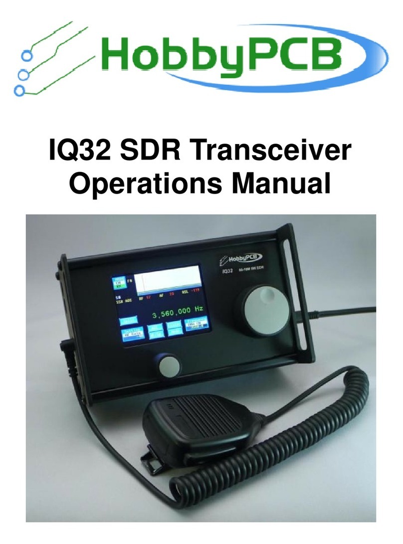
HobbyPCB IQ32 User manual

IQ32 SDR Transceiver
Operations Manual
Software Version 1.200
Manual Revision February 19, 2020

IQ32 SDR TRANSCEIVER OPERATIONS MANUAL
P a g e | i
Table of Contents
Introduction................................................................................................................................ 1
Specifications ............................................................................................................................ 2
Interface and Control Reference................................................................................................ 3
Left Side Panel....................................................................................................................... 3
Right Side Panel.................................................................................................................... 4
Front Panel ............................................................................................................................ 5
Rotary Encoders .................................................................................................................... 5
Screen Navigation.................................................................................................................. 6
Installation ................................................................................................................................. 8
Required Accessories ............................................................................................................ 8
Optional Accessories.............................................................................................................. 8
Setup...................................................................................................................................... 8
Startup ................................................................................................................................... 8
Configuration.......................................................................................................................... 8
Firmware Upgrade ................................................................................................................. 9
Public Source Files ................................................................................................................ 9
Operation................................................................................................................................. 10
Non-Volatile Memory.............................................................................................................11
Home Screen....................................................................................................................... 12
Mode Selection.................................................................................................................... 13
Settings Screens.................................................................................................................. 16
Main Settings.................................................................................................................... 17
Advanced Settings............................................................................................................ 18
Function Editing with a Keyboard..................................................................................... 20
Keyboard Fn Setting......................................................................................................... 21
Screen Fn Settings........................................................................................................... 29
Tags Settings.................................................................................................................... 32
Frequency Tuning ................................................................................................................ 36
Frequencies Screen............................................................................................................. 37
Receive Filter Settings......................................................................................................... 40
Keyer Operation................................................................................................................... 41
Hang Time........................................................................................................................ 42

IQ32 SDR TRANSCEIVER OPERATIONS MANUAL
P a g e | ii
Screen Calibration ............................................................................................................... 43
CW Operation.......................................................................................................................... 44
Split Operation.................................................................................................................. 45
Keyboard Operation in CW............................................................................................... 47
FFT Display...................................................................................................................... 48
SSB Operation......................................................................................................................... 49
PSK Operation......................................................................................................................... 51
AGC Modes Explained ............................................................................................................ 54
CW AGC .............................................................................................................................. 54
Digi AGC.............................................................................................................................. 54
SSB AGC............................................................................................................................. 54
Off........................................................................................................................................ 54
Radio Setup............................................................................................................................. 55
Receiver............................................................................................................................... 55
Transmitter........................................................................................................................... 55
Frequency Calibration.......................................................................................................... 57
S Meter Calibration .............................................................................................................. 59
Appendix –Tags, Macros, Buttons, and Keyboard.................................................................. 60
Tags ..................................................................................................................................... 60
Macros................................................................................................................................. 61
Default On-Screen Button Functions.................................................................................... 62
SSB HOME SCREEN Buttons.............................................................................................. 62
CW HOME SCREEN Buttons ............................................................................................... 62
PSK HOME SCREEN Buttons.............................................................................................. 62
Keyboard Function Keys...................................................................................................... 63
Block Diagrams ....................................................................................................................... 64
Keyboard Cheat Sheet ............................................................................................................ 65
F1: Call CQ.......................................................................................................................... 65
F2: Send Your Name and QTH............................................................................................ 65
F3: Send your Rig information ............................................................................................. 65
F4: Send your Antenna information...................................................................................... 65
F5: Confirm Called Station Name and Callsign, and send Back to You (BTU)..................... 65
F6: Send Thank You and Best Wishes (73's)....................................................................... 65
F7: Change to USB mode.................................................................................................... 65

IQ32 SDR TRANSCEIVER OPERATIONS MANUAL
P a g e | iii
F8: Change to LSB mode..................................................................................................... 65
F9: Change to CW mode ..................................................................................................... 65
F10: Toggles Transmitter Between Receive and Transmit Mode ......................................... 65
F11: Clear Transmit Buffer ................................................................................................... 65
F12: Step through Memory Buttons, Memory 1 to Memory 5............................................... 65
LEFTARROW and RIGHTARROW: Increase or decrease tuning resolution...................... 65
UPARROW and DOWNARROW: Step through Memory 1 to Memory 14.......................... 65

IQ32 SDR TRANSCEIVER OPERATIONS MANUAL
P a g e | iv
Table of Figures
Figure 1: Left Side Panel........................................................................................................... 3
Figure 2: Right Side Panel......................................................................................................... 4
Figure 3: Front Panel................................................................................................................. 5
Figure 4: Sign-On ("Splash") Screen....................................................................................... 10
Figure 5: PSK Home Screen ................................................................................................... 10
Figure 6: CW Home Screen..................................................................................................... 12
Figure 7: Mode Icon................................................................................................................. 13
Figure 8: Mode Selection Screen ............................................................................................ 13
Figure 9: USB Button............................................................................................................... 13
Figure 10: USB Home Screen................................................................................................. 13
Figure 11: CW Button .............................................................................................................. 14
Figure 12: CW Home Screen................................................................................................... 14
Figure 13: PSK Button............................................................................................................. 14
Figure 14: PSK Home Screen ................................................................................................. 14
Figure 15: Tune Button............................................................................................................ 15
Figure 16: Tune Operation....................................................................................................... 15
Figure 17: Setting WidgetAbove the Left Rotary Encoder....................................................... 16
Figure 18: Settings Menu Screen........................................................................................... 16
Figure 19: Advanced Screen ................................................................................................... 18
Figure 20: Move Cursor with Arrow Key .................................................................................. 20
Figure 21: Use TAB to Select the Label................................................................................... 20
Figure 22: Keyboard Fn Screen............................................................................................... 21
Figure 23: Function Key F1 ..................................................................................................... 22
Figure 24: Function Key F2 ..................................................................................................... 23
Figure 25: Function Key F3 ..................................................................................................... 23
Figure 26: Function Key F4 ..................................................................................................... 24
Figure 27: Function Key F5 ..................................................................................................... 24
Figure 28: Function Key F6 ..................................................................................................... 25
Figure 29: Function Key F7 ..................................................................................................... 25
Figure 30: Function Key F8 ..................................................................................................... 26
Figure 31: Function Key F9 ..................................................................................................... 26
Figure 32: Function Key F10 ................................................................................................... 27
Figure 33: Function Key F11.................................................................................................... 27
Figure 34: Function Key F12 ................................................................................................... 28
Figure 35: Screen Fn Screen................................................................................................... 29
Figure 36: SSB AGC Button Programming Screen.................................................................. 30
Figure 37: SSB Waterfall / Spectrum Button Programming ..................................................... 30
Figure 38: SSB Filter Button Programming.............................................................................. 31
Figure 39: SSB Mode Button Programming............................................................................. 31
Figure 40: Tag Screen ............................................................................................................. 32
Figure 41: MyName Tag .......................................................................................................... 33
Figure 42: MyCall Tag.............................................................................................................. 33
Figure 43: QTH (location) Tag ................................................................................................. 34

IQ32 SDR TRANSCEIVER OPERATIONS MANUAL
P a g e | v
Figure 44: Rig (radio type) Tag ................................................................................................ 34
Figure 45: Ant (antenna type) Tag ........................................................................................... 35
Figure 46: T6 Tag..................................................................................................................... 35
Figure 47: Frequency Tuning................................................................................................... 36
Figure 48: Minimum Tuning Step of 1 Hz................................................................................. 36
Figure 49: Tuning Step of 100 Hz............................................................................................ 36
Figure 50: Memory Manager Screen....................................................................................... 37
Figure 51: Memory Button Label Editing.................................................................................. 38
Figure 52: Transverter Offset Adjustment................................................................................ 38
Figure 53: Setting F Offset....................................................................................................... 39
Figure 54: Transverter Operating Frequency........................................................................... 39
Figure 55: Filter Selection........................................................................................................ 40
Figure 56: Keyer Modes .......................................................................................................... 41
Figure 57: Splash Screen........................................................................................................ 43
Figure 58: Calibration Screen................................................................................................. 43
Figure 59: CW Home Screen................................................................................................... 44
Figure 60: CW Split Operation Setup Screen.......................................................................... 45
Figure 61: CW Split Operation - Transmit Frequency Screen.................................................. 45
Figure 62: CW Split Operation Screen .................................................................................... 46
Figure 63: Station Call Sign and Name.................................................................................... 47
Figure 64: FFT Spectrum View................................................................................................ 48
Figure 65:Waterfall View.......................................................................................................... 48
Figure 66: SSB Home Screen ................................................................................................. 49
Figure 67: PSK Home Screen ................................................................................................. 51
Figure 68: VFO Tuned to 7070kHz.......................................................................................... 51
Figure 69: Decoded Signal at 14,073,548Hz........................................................................... 52
Figure 70: VFO Set At 14071kHz ............................................................................................ 52
Figure 71: Starting a QSO With Function Key F1.................................................................... 53
Figure 72: Text From The Keyboard........................................................................................ 53
Figure 73: Proper Mic Gain...................................................................................................... 55
Figure 74: Low Mic Gain.......................................................................................................... 55
Figure 75: High Mic Gain......................................................................................................... 55
Figure 76: Set TX Power Level................................................................................................ 56
Figure 77: Tuning in 15MHz WWV .......................................................................................... 57
Figure 78: Red line is WWV..................................................................................................... 57
Figure 79: Red Cursor, Blue WWV.......................................................................................... 58
Figure 80: Frequency is calibrated .......................................................................................... 58
Figure 81 S Meter Calibration.................................................................................................. 59
Figure 82: RF Section Block Diagram ..................................................................................... 64
Figure 83: Digital Section Block Diagram ................................................................................ 64

IQ32 SDR TRANSCEIVER OPERATIONS MANUAL
P a g e | vi
Terminology
•Screen Names: All screen names have the first letter capitalized and appear in Bold
with Small Caps –SETTING SCREEN
•Button Names: All button names have the first letter capitalized and the complete name
in Bold, no small caps - Advanced
•Widget Names: All widget names have the first letter capitalized and the complete
name in Bold - Mode
•Tags: All tags are bold and blue - <StnCS> (51,51,255)
•Macros: All macros are bold and violet - <USB> (153, 0, 255)
•Fn Keys: Keyboard Fn keys are bold and highlight yellow - F3
•Widget and Icon refer to the same on-screen feature
•HOME SCREEN and OPERATION SCREEN refer to the same screen
•Factory default values are bold and green - 0 = Straight (0, 176, 80)

IQ32 SDR TRANSCEIVER OPERATIONS MANUAL
P a g e | 1
Introduction
Thank you for purchasing a HobbyPCB IQ32 transceiver. On behalf of all our design and de-
velopment contributors, we appreciate your support of our products.
The HobbyPCB IQ32 is a 5 Watt Software Defined Radio. It operates on all amateur radio fre-
quencies from 80M up to 10M. Native operating modes are USB, LSB, CW and PSK31. There
is a built in keyer for CW operation and a PSK encoder and decoder for PSK operation.
The IQ32 does not require an external computer to take advantage of all the features.
The operating firmware of the IQ32 is easily upgraded by downloading the latest firmware to a
memory stick. The memory stick is connected to the USB port on the radio and the radio han-
dles the upgrade.
Connect a suitable antenna or dummy load and a power supply. Remember, you are respon-
sible for the radio, and you must ensure that any emissions are on a proper frequency (one for
which you are properly licensed and allowed to transmit).

IQ32 SDR TRANSCEIVER OPERATIONS MANUAL
P a g e | 2
Specifications
•Frequency Range:
oReceive: 3 –30MHz
oTransmit: 80, 60, 40, 30, 20, 17, 15, 12, 10M Amateur Bands. Performance is
guaranteed on these bands.
•Receiver
oFilters: 0 –4000, 300 –3300, 300 - 2700, 300 - 1300, 400 - 700, 500 - 600Hz
oSensitivity: MDS < -128 dBm on 80M dropping to < -135 dBm on 10M
oNoise Figure: < 8dB
oAGC: CW, Digi, SSB, Off
•Transmitter
oTransmit Power: 5 Watt typical, 4 Watt minimum
▪Power Amp: Class A
oLO Feed-thru < -50 dBc @ 5W output
oSpurious and Harmonics < -50dBc typical
oBuilt-In Keyer
▪5 to 35 WPM
▪Iambic Mode A & B
▪Adjustable dot dash weighting
▪Straight key mode
•DC Power: 13.8VDC, 2A max.
o10VDC minimum
o15VDC maximum
•Antenna Connector: BNC
•Antenna Port: The IQ32 can tolerate short duration antenna faults ranging from short to
open circuit. Good operating practice dictates that a match of 3:1 or better is required
for efficient long-term operation
•Size: 172mm x 105mm x 75mm, 6.8” x 4.1” x 3.0”
•Weight: < 700 grams, 1.5 LBs
•Display: 3.2” Color LCD Touchscreen
•Operating Modes: USB, LSB, CW, PSK31
•Microphone: RS-UV3 Speaker Mic or compatible device
•DSP Processor: STM32F407, 32 Bit
oSample rate: 8000Hz
•Keyboard: PS2 Keyboard

IQ32 SDR TRANSCEIVER OPERATIONS MANUAL
P a g e | 3
Interface and Control Reference
Left Side Panel
1. RX I/Q Output –3.5mm TRS
a. Tip –I
b. Ring –Q
c. Sleeve –Ground
2. Headphone Output - 3.5mm TRS
a. Tip –Left
b. Ring –Right
c. Sleeve –Ground
3. Speaker/Mic –3.5mm TRRS
a. Tip –SPKR
b. Ring 1 –MIC
c. Ring 2 –PTT
d. Sleeve –Ground
4. CW Key –3.5mm TRS
a. Tip –Dit (Straight Key)
b. Ring –Dot
c. Sleeve –Ground
Figure 1: Left Side Panel

IQ32 SDR TRANSCEIVER OPERATIONS MANUAL
P a g e | 4
Right Side Panel
1. Power Switch
2. Power Amp connection –3.5mm, TRS
a. Tip –Band Data
b. Ring –PTT
c. Sleeve –Ground
3. Power Connector –5mm X 2.1mm, center positive
4. PS2 Keyboard Connector
5. USB Type A
6. Antenna connection, BNC
Figure 2: Right Side Panel

IQ32 SDR TRANSCEIVER OPERATIONS MANUAL
P a g e | 5
Front Panel
1. LCD touch screen (Control Screen) for access to most user interface functions, setup
and control.
2. Frequency control, right rotary encoder
3. Left rotary encoder for adjusting parameters such as AF gain and selection of some
functions.
Rotary Encoders
Rotary encoders have 3 possible methods of operation:
1. Rotating the knob clockwise or counterclockwise will increase or decrease the desired
parameter.
2. Pressing and releasing the knob will change a specific parameter.
3. Pressing, rotating and then releasing the knob will increase or decrease a parameter or
select a new sub function, which may only be available while the knob is pressed.
Right Rotary Encoder –Frequency Control
•Frequency Adjustment - rotate
•Press, rotate and release
oChange the frequency step size: 1, 10, 100, etc Hz
The right rotary encoder, on the front panel, selects the desired operating frequency for trans-
mit and receive. It is also used to calibrate the touch screen and to initiate a firmware upgrade.
Left Rotary Encoder
•Rotate –adjust AF gain: 0 to 100. Other parameters are adjusted with this control.
•Press and release –change filter bandwidth.
•Press, rotate and release –select a new function to be adjusted
The left rotary encoder below the touch screen is mainly used as the AF gain control. Other
functions such as Mic Gain, TX Level, Sidetone gain are also available on this control. It is
used for parameter selection in many of the setting functions. Pressing and releasing this con-
trol while in receive mode will change the audio filter bandwidth.
1
2
3
Figure 3: Front Panel

IQ32 SDR TRANSCEIVER OPERATIONS MANUAL
P a g e | 6
Screen Navigation
The following is a navigation chart for all the
available functions of the IQ32. Each function
will be described in detail in this manual. The
range of values and the factory reset value
are shown where appropriate.
Home Screen
•Mode (Widget)
oUSB
oLSB
oCW
oCWR
oPSK-U
oPSK-L
oTune
•Split (CW)
oSet Tx
oJoin
•CS (CW & PSK)
oContact Call Sign
•NM (CW & PSK)
oContact Name
•Tune ^ (PSK)
oTune v (PSK)
•Settings
oAF Gain
▪0 to 100
▪70
oRF Gain
▪0 to 100
▪100
oAGC Mode
▪0 CW
▪1 Digi
▪2 SSB
▪3 Off
oMic Gain
▪0 to 80
▪30
oTX Level
▪-6 to 22
▪22
oSide Tone
▪-6 to 29
▪20
oCW Speed
▪5 to 35 WPM
▪12
oCW Weight
▪7 to 15
▪10
oAdvanced
▪Key Mode
•0 = Straight
•1 = Iambic A
•2 = Iambic B
•3 = Weight Dah
•4 = Weight Dit/Dah
▪Mic Bias
•0 = Bias Off
•1 = Bias On
▪AGC Thrsh
•50 to 1000
•400
▪RSL Cal
•-140 to -100
•-115
▪Freq Cal
•-100 to 100
•0
▪Factory Rst
▪Cal. Screen
oKeyboard Fn
▪1 Call
▪2 Name
▪3 Rig
▪4 Ant
▪5 BTU
▪6 TNX
▪7 USB
▪8 LSB
▪9 CW
▪10 TxRx
▪11 Clr
▪12 Mem
▪Tags
▪Done

IQ32 SDR TRANSCEIVER OPERATIONS MANUAL
P a g e | 7
oScreen Fn
▪SSB –AGC
•<NxAGC>
▪SSB –WF / Sp
•<WF/Sp>
▪SSB –Filter
•<NxFil2>
▪SSB –Mode
•<NxMode><NoFilt>
▪CW –AGC
•<NxAGC>
▪CW –WF / Sp
•<WF/Sp>
▪CW –Filter
•<NxFil5>
▪CW –Mode
•<NxMode><NoFilt>
▪PSK - WF / Sp
•<WF/Sp>
▪PSK - Mode
•<NxMode><NoFilt>
▪Tags
▪Done
oTags
▪MyName
•John Doe
▪MyCall
•A1BCD
▪QTH
•My Home
▪Rig
•IQ32 SDR
▪Ant
•Dipole
▪T6
▪T7
▪T8
▪T9
▪T10
▪T11
▪T12
•LO Freq. (Memory Manager)
oMemory 1
▪3,560,000 Hz, CW
oMemory 2
▪7,040,000 Hz, CW
oMemory 3
▪14,060,000 Hz, CW
oMemory 4
▪21,060,000 Hz, CW
oMemory 5
▪10,000,000 Hz, USB
oMemory 6
▪3,580,000 Hz, PSK-U
oMemory 7
▪7,070,000 Hz, PSK-U
oMemory 8
▪14,070,000 Hz, PSK-U
oMemory 9
▪21,080,000 Hz, PSK-U
oMemory 10
▪15,000,000 Hz, USB
oMemory 11
▪3,985,000 Hz, LSB
oMemory 12
▪7,285,000 Hz, LSB
oMemory 13
▪14,285,000 Hz, USB
oMemory 14
▪29,000,000 Hz, USB
oF Offset
▪000,000,000
oEdit
oLO Freq
•AGC
oCW for CW
oDigi for PSK
oSSB for SSB
oOff
•WF/Sp
oSp for CW and SSB
oWF for PSK
•Filter
oF0 = 0 - 4,000 Hz
oF1 = 300 - 3300 Hz
oF2 = 300 –2700 Hz
oF3 = 300 - 1300 Hz
oF4 = 400 - 700 Hz
oF5 = 500 - 600 Hz
•Mode (Button)
oUSB
oLSB
oCW
oPSK-U
oPSK-L

IQ32 SDR TRANSCEIVER OPERATIONS MANUAL
P a g e | 8
Installation
Required Accessories
•Power Supply: 13.8VDC, minimum 2A
•Power cable between the power supply and the IQ32, with an in-line fuse
•Coax to connect IQ32 to the dummy load or antenna
•Antenna
Optional Accessories
•Speaker / Microphone
•Headphones
•Straight Key
•50 Ohm dummy load rated for at least 5 Watts
•Paddle
•PS2 Keyboard
•Stylus for touch screen operation
Setup
1. Be sure the power switch, on the right-side panel, is in the off position.
2. Verify that the power supply is set at 13.8VDC then turn off the power supply.
3. Connect the speaker microphone to the appropriate jack on the left side panel.
4. Connect the dummy load or antenna, using a coax, to the BNC connector on the right-
side panel.
5. Connect the power supply to the power jack on the right-side panel.
6. If you have a straight key or paddle, connect it to the Key jack on the left side panel.
7. If you have a PS2 keyboard, connect it to the PS2 keyboard connector on the right-side
panel.
Startup
1. Turn on the power supply.
2. Turn on the power switch on the right-side panel of the IQ32.
3. A SPLASH SCREEN will be displayed followed by the HOME SCREEN.
4. If the touch screen has never been calibrated, turn off the power switch on the right-side
panel.
5. Turn on the power switch on the right-side panel of the IQ32.
6. Immediately, press and hold both rotary encoder knobs until the CALIBRATION SCREEN
appears.
7. Follow the on-screen instructions to calibrate the touch screen.
Configuration
1. Using the Screen Navigation chart from the previous section, be sure the Mic Bias is
set appropriate for your microphone. This is found on the ADVANCED SCREEN.
2. If you will be using a straight key or paddle, set the Key mode appropriately. This is
found on the ADVANCED SCREEN.

IQ32 SDR TRANSCEIVER OPERATIONS MANUAL
P a g e | 9
3. If you will be using a paddle, set the CW Speed and CW Weight, found on the SET-
TINGS SCREEN,as you desire.
4. For CW and PSK use, set the Side Tone level from the SETTING SCREEN.
5. If you have a keyboard attached to the IQ32, set the following parameters in Tags:
a. MyName
b. MyCall
c. QTH
d. Rig
e. Ant
6. Found on the SETTING SCREEN, set Mic Gain to 30 for the RS-UV3 microphone. This is
a starting point for other microphones, but adjustment will most likely be necessary.
7. Be sure the transmitter is set for a valid amateur radio frequency. With a power meter
and dummy load attached, select the Tx Level, found on the SETTINGS SCREEN.Touch
the Tune button on the MODE SCREEN, to begin transmitting. Set the Tx Level for 5
Watts output. Touch the Tune button to turn off the transmitter
Firmware Upgrade
The latest released executable images are posted on GitHub at following link:
https://github.com/ve7pke/IQ32-Files
•Download the most recent zip file and save it to a safe location on your computer. Unzip
this file.
•Place the image.bin file in the root of a USB flash drive having a capacity of 4GB or less.
•With the IQ32 powered off, insert the USB drive into the USB connector on the right-
side panel of the IQ32.
•Press and hold down the frequency encoder while powering on the IQ32.
•The screen will remain white - you can release the encoder and wait for the unit to finish
loading (~15 s).
•Once the program has loaded, the unit will automatically boot into normal operation.
•Check the new build version and date on the splash screen during boot.
Public Source Files
Source files are located on GitHub at the following link:
https://github.com/iq32-sdr/Source
Building your own image from the source files is not encouraged unless you are experienced
with proper operation of the compiler.
Caution: Installing modified firmware could brick your device unless you know what you are
doing. Writing the binary file directly to ROM will overwrite the factory installed bootloader and
will prevent the loading of released firmware via a USB flash drive.

IQ32 SDR TRANSCEIVER OPERATIONS MANUAL
P a g e | 10
Operation
Turn on the power switch located on
the right-side panel. You will see the
SPLASH SCREEN as depicted in Figure
4. It announces the version of the
software you are running. This pic-
ture shows the current version at the
time of preparation of this document.
We expect the software will continue
to evolve, and it is always possible
that there has been an update to the
firmware that has been released be-
tween updates to the documentation.
After a few seconds, you should see
the screen pictured in Figure 5. It is
the HOME SCREEN.
From here you can start your journey,
at each subsequent power-up, you
will be returned to the HOME SCREEN
after the SPLASH SCREEN is briefly
displayed.
The software has multiple screens
that are accessed by touching the
appropriate place on the touchscreen.
These widgets are multifunction. The
top line indicates the name of the
widget, what secondary screen or
function it selects, what option is cur-
rently selected and the value of the
option. These are all in a touch sensi-
tive area on the screen.
Figure 5: PSK Home Screen
Figure 4: Sign-On ("Splash") Screen

IQ32 SDR TRANSCEIVER OPERATIONS MANUAL
P a g e | 11
Non-Volatile Memory
Most configuration and operating parameters are saved in non-volatile memory. As you config-
ure the IQ32 on the varied setting screens, program screen function key operations and key-
board Fn key operations, these settings are preserved for future use. When the power is
turned off and later restored, the value of the many parameters retrieved from memory are the
same as previously defined.
Frequency of operation, mode, filter, AGC, split frequency, Tx Level and frequency increment
step size are saved in the last selected memory location, Memory 1 –Memory 14. These
memory locations are discussed in a later section of this manual.
The offset frequency, typically used for transverter operation, is also saved in this memory.

IQ32 SDR TRANSCEIVER OPERATIONS MANUAL
P a g e | 12
Home Screen
The following features are displayed
on the Home Screen, Figure 6:
•Filter selection: As shown in the figure to the right, the selected filter is
F3 (300 –1300 Hz) and the relative bandwidth is shown by the yellow
bar under the spectrum display.
•S Meter: In the figure to the right, the S Meter reading
is S6 and the signal strength is shown by the green
bar under the spectrum and filter.
•AGC: Just below the S6 in the figure to the right, the AGC selection is CW.
AGC operation will be described in a later section of this manual.
•Call and Name: For CW and PSK operation, the but-
tons shown at the right are displayed on the HOME
SCREEN. With a PS2 keyboard attached to the IQ32 you may enter the call sign and the
name of your contact. They will be transmitted as configured for the keyboard Fn keys.
This is discussed in a later section of this manual.
•Split: This button appears in CW mode. It ena-
bles split transmit and receive frequency opera-
tion. More details are available in the section on CW operation.
•The remainder of the buttons and widgets are covered in detail in later sections.
Figure 6: CW Home Screen

IQ32 SDR TRANSCEIVER OPERATIONS MANUAL
P a g e | 13
Figure 10: USB Home Screen
Mode Selection
Figure 7 is the Mode icon or Mode widget. Pressing it will bring you to the
MODE SELECTION SCREEN. The current mode is PSK-U (PSK in USB) and we
are currently in Receive (RX). If you touch the Mode widget (upper left cor-
ner of the screen) you will switch to the MODE SELECTION SCREEN (Figure 8,
depicted below).
Mode selection may also be accomplished by pressing, rotating to the de-
sired parameter and releasing the left rotary encoder.
On the MODE SELECTION SCREEN, you
can select the operating mode you
desire, by touching the appropriate
on-screen button. It will switch to the
desired mode and the mode’s HOME
SCREEN. If you selected the wrong
mode, you must hit the Mode button
(Figure 7) on the HOME SCREEN to
return to the MODE SELECTION
SCREEN. Then select the desired
mode.
Touch the LSB (USB) button (Figure
9) to go to the LSB HOME SCREEN
(Figure 10).
Once on the LSB HOME SCREEN, or
any HOME SCREEN, you can either
operate the radio, access the
MEMORY MANAGER (LO Freq. widget),
or access the SETTINGS SCREEN.
The frequency of operation is now
displayed in large green digits be-
tween the FFT window (waterfall or
spectrum display) and the widg-
ets/buttons on the bottom third of the
screen. This is true for not only the
LSB HOME SCREEN as shown in Fig-
ure 10, but also on the USB HOME
SCREEN, the CW HOME SCREEN, and
the CWR HOME SCREEN.
Figure 8: Mode Selection Screen
Figure 9: USB Button
Figure 7: Mode
Icon
Other manuals for IQ32
1
Table of contents
Other HobbyPCB Transceiver manuals