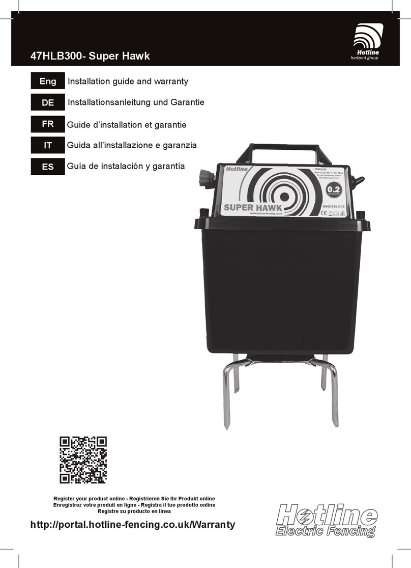
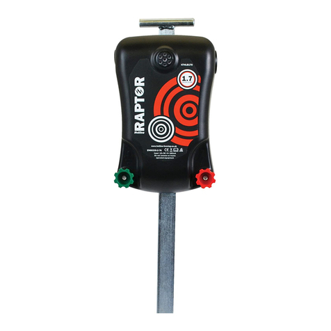
Hotline 47HLB500 Operating and maintenance manual

Eng
DE
FR
IT
ES
47HLB500/47HLB525 - Falcon/Buzzard
Installation guide and warranty
Installationsanleitung und Garantie
Guide d’installation et garantie
Guida all’installazione e garanzia
Guía de instalación y garantía
Register your product online - Registrieren Sie Ihr Produkt online
Enregistrez votre produit en ligne - Registra il tuo prodotto online
Registre su producto en línea
http://portal.hotline-fencing.co.uk/Warranty


Base1.
Ground connection terminal2.
Fence connection terminal3.
On off switch4.
Low battery/pulse indicator5.
High/low switch6.
Thumbscrews for removing base7.
Ground connection leads8.
Fence connection lead9.
12v connection leads10.
Battery input connection (base removed)11.
Key
What’s in the box? Getting to know the energiser
Please read through before installation. Please read safety guidelines leaet.
Installation guide - Type HLB3 - 47HLB500/525 - Falcon/Buzzard
5
4
6
7
8
9
10
2
1
3
11

Connecting it all together
Unscrew the thumb screws and remove the
energiser top from the battery box.
The energiser is operated from external 12v battery. .
If not already inserted, clip the 12v lead into
the connector in the base of the energiser
top.
Position the lead through the slot in the
battery box and replace the energiser top,
securing with the thumb screws.
Connect the croc clips to the battery. If the
energiser beeps, the croc clips are on the
wrong terminals
12v battery connection (external) 7
10
10

Fence connection
Turning on and off, switching high and low Pulse/low battery indicator
Connect the lead with the red croc clip
to the fence (from red terminal) & the
green croc clip (from the green terminal)
to the ground rod. We recommend a
minimum of one ground road driven
approx. one metre into the ground.
Connection to the fence
The light on the front of the energiser
will ash green with every pulse. As
your battery loses power, it will start
to ash red indicating that you need to
charge the 12v battery.
Lead connection
Unscrew the terminals enough to slide in
the fork terminals on the earth and fence
leads. Securely tighten.
OFF
HIGH
ON
LOW
8
8
9
9

Trouble shooting
You should have a minimum of 3kv on your fence line to be effective. In principle, electric
fencing is a simple concept. If your energiser is working then there can only be two other
places to look - your fence line or ground system.
Sound and sight - Most energisers emit an audible tick caused by the ring of the output
transformer. This is a good indication that the energiser working. The indicator light or fence
monitor should be pulsing or ashing. The energiser has a pulse indicator, and this should
be operating at all times. If the light is ashing green it usually means that the energiser
is working correctly. This indicates that the problem is somewhere on the fence system. If
red then your battery needs charging. Flash test - disconnect the croc clips from the fence
and ground stake. Clip the croc clips together making sure the metal jaws contact each
other. Slowly draw them apart - you should get a short (1-2mm)spark jumping from one to
the other. Use a Tester - disconnect completely from the ground stake and fence and take
a reading across the terminals. Depending on the model of energiser you should have a
reading between 7 and 10kv.
Low voltage - If there is high voltage on your ground stake it is missing from your fence line.
The greater the depth and surface area under the ground the more efciently your ground
stake will collect the pulse as it returns through the earth. If you get a shock from your ground
stake, or your tester shows voltage when touched to the ground stake, you can improve
your whole system by adding further ground stakes. Link additional ground stakes with wire,
spacing them about a metre apart.
Clear lines - An electric fence operates as an open circuit. The fence is positive and the
ground itself is negative. By touching both fence and ground the animal completes the circuit
and get the shock. If anything touches both ground and fence, other than the animal, it
reduces the effective voltage on the fence line. The fence line must not touch anything that is
not insulated from the ground. Check the fence line is clear from all vegetation and wooden
posts, metal posts and gates are not touching the line. Check all insulators. The fence line
can occasionally come unhooked from insulators and touch the posts and broken insulators
can cause leaking of power into the post and ground. Line problems - If you are joining
two sections of tape or wire, try to use correct connectors to ensure the conductors in both
sections are connected. Check the condition of the line, if the metal conductors within the
line are broken it will effect the efciency of the fence. Greater metal content means greater
efciency. Netting - Netting is closer to the ground than other forms of fence so requires
more maintenance to keep clear from vegetation. All horizontal lines, apart from the bottom,
must be kept clear from the ground. If your net is sagging and touching the ground, add
in extra posts. The net must also be clear of contact from other forms of fencing, arks and
chicken wire runs. Check the metal spikes on the posts, occasionally wires can get caught
up or slip down to the metal spike and take power to ground. Remember- if your energiser
and ground system is ne, the problem will be somewhere on your fence line!
If in doubt, Call - We are always happy to help. +44(0)1626 33 11 88
Checking the energiser
Checking the ground system
Checking the fence line

1. Basis
2. Erdungsanschlussklemme
3. Zaunanschlussklemme
4. An-/Aus-Schalter
5. Schwache-Batterie-/Impuls-Anzeige
6. Hoch-/Niedrig-Schalter
7. Flügelschrauben zur Demontage der Basis
8. Erdungsanschlussleitungen
9. Zaunanschlussleitung
10. 12-Volt-Anschlussleitungen
11. Batterie-Eingangsanschluss (bei abgebauter
Basis)
Legende
Was ist in der Kiste? Lernen Sie das Elektrozaungerät kennen
Bitte vor der Installation durchlesen. Bitte Merkblatt mit den Sicher-
heitshinweisen durchlesen.
Installationsanleitung - 47HLB500/525 - Falcon/Buzzard
5
4
6
7
8
9
10
2
1
3
11
DE.indd 1 18/02/2019 11:10:13

Alles miteinander verbinden
Lösen Sie die Flügelschrauben und nehmen
Sie den oberen Teil des Elektrozaungeräts
vom Batteriefach ab.
Das Elektrozaungerät (Energiser) kann mit einer 6- oder 12-Volt-Batterie betrieben
werden. In das Batteriefach passen 6-Volt-Batterien (47P44), so dass das Gerät leicht
zu transportieren ist. Verbraucherbatterien in Standardgröße werden von außerhalb des
Batteriefachs betrieben.
Falls noch nicht geschehen,
stecken Sie die 12-Volt-Leitung in
dieBuchse an der Basisdes oberen
Teils des Elektrozaungeräts.
Führen Sie die Leitung durch die
Nut im Batteriefach, setzen Sie den
oberen Teil des Elektrozaungeräts
wieder auf das Batteriefach und
ziehen Sie die Flügelschrauben
wieder an.
Schließen Sie die Sicherheits-
Abgreifklemmen (Croc Clips)
an die Batterie an. Wenn das
Elektrozaungerät piept, sind die
Sicherheits-Abgreifklemmen
an den falschen Anschlüssen
angebracht.
12-Volt-Batterieanschluss (extern) 7
10
10
DE.indd 2 18/02/2019 11:10:13

Das Elektrozaungerät (Energiser) kann mit einer 6- oder 12-Volt-Batterie betrieben
werden. In das Batteriefach passen 6-Volt-Batterien (47P44), so dass das Gerät leicht
zu transportieren ist. Verbraucherbatterien in Standardgröße werden von außerhalb des
Batteriefachs betrieben.
Zaun-Anschluss
Ein- und Ausschalten, Hoch- und Niedrig-Schalten Impuls-/Schwache-Batterie-Anzeige
Schließen Sie die Leitung mit der
roten Sicherheits-Abgreifklemme
(Croc Clip) an den Zaun (von der
roten Anschlussklemme) und die
grüne Sicherheits-Abgreifklemme
an den Staberder an (von der
grünen Anschlussklemme). Wir
empfehlen mindestens einen
Staberder ca. einen Meter in den
Erdboden einzuschlagen.
Anschluss an den Zaun
Die Lampe an der Vorderseite des
Elektrozaungeräts blinkt bei jedem
Impuls grün. Sobald sich Ihre Batterie
entlädt, beginnt sie rot zu blinken, um
anzuzeigen, dass Sie die 6-Volt-Batte-
rie wechseln oder die
12-Volt-Batterie laden müssen.
Leitungsanschluss
Lösen Sie die Anschlussklemmen
soweit, bis Sie die Kabelschuhe
(in Gabelform) auf die Erdungs-
und Zaunleitung schieben können.
Fest anziehen.
AUS
HOCH
EIN
NIEDRIG
8
8
9
9
DE.indd 3 18/02/2019 11:10:13

Fehlersuche
Um die Effektivität sicherzustellen, sollten Sie eine Spannung von mindestens 3 kV an Ihrem Zaun anliegen
haben. Das Konzept von Elektrozäunen ist grundsätzlich recht einfach. Wenn Ihr Elektrozaungerät funktioniert,
gibt es nur zwei andere Stellen, die Sie überprüfen können - Ihre Zaunleitung oder das Erdungssystem.
Sehen und Hören - Bei den meisten Elektrozaungeräte ist ein rhythmisches Ticken wahrnehmbar, das
durch die Zündung des Ausgangstransformators verursacht wird. Dies ist ein gutes Zeichen dafür, dass das
Elektrozaungerät ordnungsgemäß funktioniert. Die Anzeigenleuchte bzw. der Zaunmonitor sollte aufackern
oder blinken. Das Elektrozaungerät verfügt über eine Impuls-Anzeige und diese sollte immer in Betrieb
sein. Wenn die Leuchte grün blinkt, bedeutet dies gewöhnlich, dass das Elektrozaungerät ordnungsgemäß
funktioniert. Dies weist auf ein Problem innerhalb der Zaunanlage hin. Blinkt die Leuchte rot, muss die
Batterie aufgeladen werden. Flash-Test - Trennen Sie die Sicherheits-Abgreifklemmen vom Zaun und vom
Staberder. Klemmen Sie die Sicherheits-Abgreifklemmen zusammen und stellen Sie sicher, dass sich die
Metallbacken berühren. Ziehen Sie sie langsam auseinander - es sollte ein kleiner (1-2 mm) Funke von
einem Anschluss zum anderen überspringen. Testgerät verwenden - Vollständig vom Staberder und Zaun
trennen und eine Ablesung an den Anschlüssen vornehmen. Je nach Modell des Elektrozaungeräts sollte
ein Messwert zwischen 7 und 10 kV abgelesen werden.
Niedrige Spannung - Falls am Staberder eine hohe Spannung anliegt, fehlt diese an der Zaunleitung. Je
größer die Tiefe und Fläche unter der Erde, desto efzienter wird der Staberder den Impuls erfassen, wenn
dieser durch die Erde zurückießt. Wenn Sie am Staberder einen Stromschlag bekommen oder Ihr Testgerät
eine Spannung anzeigt, wenn Sie es an den Staberder halten, können Sie Ihr gesamtes System verbessern,
indem Sie weitere Staberder installieren. Verbinden Sie die zusätzlichen Staberder mit Draht und stellen Sie
sie in einem Abstand von einem Meter zueinander auf.
Saubere Leitungen - Ein Elektrozaun ist als offener Stromkreis konzipiert. Der Zaun ist positiv und der
Erdboden an sich ist negativ. Wenn ein Tier nun sowohl den Zaun als auch den Erdboden berührt, schließt
es den Stromkreis und bekommt einen Stromschlag. Berührt ein anderes Objekt als ein Tier sowohl den
Erdboden als auch den Zaun, reduziert sich die effektive Spannung der Zaunleitung. Die Zaunleitung
darf mit keinem Objekt in Berührung kommen, das nicht vom Erdboden aus isoliert ist. Prüfen Sie, ob
die Zuleitung von Bewuchs befreit ist, und dass keine Holzpfosten, Metallpfosten oder Tore die Leitung
berühren. Kontrollieren Sie alle Isolatoren. Die Zaunleitung kann sich gelegentlich von den Isolatoren lösen
und die Pfosten berühren und defekte Isolatoren können zu einem Austritt des Stromes in die Pfosten und
den Erdboden führen. Leitungsprobleme - Wenn Sie zwei Klebeband- oder Drahtabschnitte miteinander
verbinden, verwenden Sie bitte die korrekten Verbindungen, um sicherzustellen, dass die Leiter in beiden
Abschnitten miteinander verbunden sind. Kontrollieren Sie den Zustand der Leitung - wenn die Metallleiter in
der Leitung defekt sind, wirkt sich dies auf den Wirkungsgrad des Zauns aus. Ein größerer Metallgehalt erhöht
den Wirkungsgrad. Maschendrahtzaun - Ein Maschendrahtzaun ist näher am Erdboden als jede andere
Art von Zaun und ist daher wartungsintensiver hinsichtlich der Beseitigung von Bewuchs. Alle horizontalen
Leitungen, außer vom Boden, müssen vom Erdboden her freigehalten werden. Wenn Ihr Maschendrahtzaun
durchhängt und den Erdboden berührt, stellen Sie weitere Pfosten auf. Der Maschendrahtzaun darf zudem
auch nicht mit anderen Zäunen, mobilen Hühnerställen oder den Maschendrahtzäunen von Hühnerhöfen
in Berührung kommen. Kontrollieren Sie die Metallspitzen an den Pfosten - gelegentlich kann der Draht
an den Metallspitzen hängenbleiben oder herunterrutschen und somit Strom zum Erdboden leiten. Bitte
beachten - Wenn Ihr Elektrozaungerät und Erdungssystem problemlos funktionieren, wird der Fehler bei
Ihrer Zaunleitung zu nden sein!
Im Zweifelsfall, rufen Sie uns an - Wir helfen Ihnen gerne. +44 (0) 1626 33 11 88
Überprüfung des Elektrozaungeräts
Überprüfung des Erdungssystems
Überprüfung der Zaunleitung
DE.indd 4 18/02/2019 11:10:13

1. Base
2. Borne de raccordement au sol
3. Borne de raccordement à la clôture
4. Interrupteur On/Off
5. Indicateur de batterie faible/d'impulsion
6. Commutateur High/Low
7. Vis papillon pour retirer la base
8. Fils de raccordement à la terre
9. Fil de raccordement à la clôture
10. Fils de raccordement au 12 V
11. Raccord d'entrée batterie (base retirée)
Légende
Que contient le carton ? Prise en main de l'électricateur
Merci de le lire entièrement avant l'installation Veuillez lire le dépliant
sur les directives de sécurité
Guide d'installation - 47HLB500/525 - Falcon/Buzzard
5
4
6
7
8
9
10
2
1
3
11
FR.indd 1 18/02/2019 11:11:33

Connexion de l'ensemble
Dévissez les vis papillon et retirez le capot de
l'électricateur recouvrant le compartiment à
batterie.
L'électricateur peut fonctionner avec une batterie de 6 V ou 12 V. Les batteries de 6 V
(47P44) vont dans le compartiment à batterie pour un transport facile. Les batteries grand
public de taille standard fonctionnent depuis l'extérieur du compartiment à batterie.
S'il n'est pas déjà inséré, clipsez le l 12 V
dans le connecteur à la base du capot de
l'électricateur.
Faites passer le l dans la fente pour
qu'il pénètre dans le compartiment
à batterie, puis remettez le capot
de l'électricateur puis vissez les
vis papillon.
Raccordez les pinces crocodile à
la batterie Si l'électricateur émet
des bips, c'est que les pinces
crocodiles sont raccordées aux
mauvaises bornes.
Connexion batterie 12 V (externe) 7
10
10
FR.indd 2 18/02/2019 11:11:33

L'électricateur peut fonctionner avec une batterie de 6 V ou 12 V. Les batteries de 6 V
(47P44) vont dans le compartiment à batterie pour un transport facile. Les batteries grand
public de taille standard fonctionnent depuis l'extérieur du compartiment à batterie.
Raccordement à la clôture
Allumage et extinction, commutation high et
low
Indicateur d'impulsion/de batterie
faible
Raccordez le l équipé de la pince
crocodile rouge (venant de la borne
rouge) à la clôture et la pince crocodile
verte (venant de la borne verte) au
piquet de terre. Nous recommandons
de rentrer le piquet de terre d'environ
un mètre dans le sol.
Raccordement à la clôture
Le voyant sur le devant de l'électrica-
teur clignote en vert à chaque impul-
sion. Tandis que votre batterie faiblit, le
voyant se met à clignoter en rouge pour
indiquer qu'il faut changer la batterie 9
V ou recharger
la batterie 12 V.
Connexion des ls
Dévissez les bornes sufsamment
pour insérer les bornes à fourche
sur les ls de terre et de clôture.
Serrez de manière sûre.
OFF
HIGH
ALLUMÉ
LOW
8
8
9
9
FR.indd 3 18/02/2019 11:11:33

Dépistage des pannes
Pour que la ligne de clôture soit efcace, il faut qu'elle se trouve sous 3 KV minimum. De par son
principe, une clôture électrique est un concept simple. Si votre électricateur fonctionne, il ne peut y
avoir que deux autres endroits à vérier : votre ligne de clôture ou le système de terre.
Sonorité et vue - La plupart des électricateurs émettent un « tic » audible occasionné par la
décharge du transformateur de sortie. Ce bruit est un bon indicateur que l'électricateur fonctionne. Le
voyant indicateur ou le moniteur de clôture devrait émettre une impulsion ou clignoter. L'électricateur
comporte un indicateur d'impulsion et cet indicateur devrait fonctionner en permanence. Si le voyant
clignote en vert, cela signie habituellement que l'électricateur fonctionne correctement. Cela indique
que le problème se situe quelque part sur le système de clôture. Si le voyant clignote en rouge :
la batterie a besoin d'être rechargée Test d'arc électrique - Déconnectez les pinces crocodiles de
la clôture et du piquet de terre. Connectez les pinces crocodiles entre elles en veillant à ce que
les mâchoires métalliques se touchent bien. Détachez-les lentement l'une de l'autre : il devrait se
produire un bref arc électrique (de 1-2 mm) entre l'une et l'autre. Utiliser un testeur - Déconnectez
complètement du piquet de terre et de la clôture et lisez la tension entre les bornes. Suivant le modèle
d'électricateur, vous devriez lire entre 7 KV et 10 KV.
Tension basse - Si une haute tension est appliquée à votre piquet de terre, elle va manquer à votre
ligne de clôture. Plus la profondeur et la surface sous le sol sont importantes et plus votre piquet de
terre va collecter efcacement l'impulsion lorsqu'elle revient à la terre. Si vous vous électrocutez au
contact du piquet de terre ou si votre testeur afche une tension au contact avec le piquet de terre,
vous pouvez améliorer l'ensemble de votre système en ajoutant des piquets de terre. Reliez des
piquets de terre additionnels avec du l métallique en les espaçant d'env. un mètre.
Lignes dégagées - Une clôture électrique opère comme un circuit ouvert. La clôture est positive et
la terre elle-même est négative. Si l'animal qui déjà touche le sol touche la clôture, il ferme le circuit
et s'électrocute. Si quelque chose d'autre qu'un animal touche à la fois la terre et la clôture, cet objet
réduit la tension efcace de la ligne de clôture. La ligne de clôture ne doit rien toucher qui ne soit pas
isolé par rapport à la terre. Vériez que la ligne de clôture est bien dégagée (ni la végétation ni des
poteaux en bois, poteaux métalliques et portails ne doivent toucher la ligne). Vériez tous les isolateurs.
Il peut arriver que la clôture se décroche des isolateurs et touche les poteaux ; des isolateurs cassés
peuvent provoquer une fuite de courant dans le poteau puis le sol. Problèmes de ligne - Si vous
connectez deux segments de ruban ou de l électrique, essayez d'utiliser des connecteurs corrects
pour assurer que les conducteurs soient connectés dans les deux segments. Vériez l'état de la
ligne : si les conducteurs métalliques sont cassés dans la ligne, cela affectera l'efcacité de la clôture.
Une plus grande quantité de métal signie une plus grande efcacité. Pose d'un let - Un let se
trouve plus près du sol que toute autre clôture ; il requiert donc plus de maintenance pour l'empêcher
d'entrer en contact avec la végétation. Toutes les lignes horizontales, hormis le bas, doivent être
maintenues distantes du sol. Si votre let a pris une forme concave et touche le sol, ajoutez des
poteaux supplémentaires. Le let doit aussi ne pas entrer en contact avec d'autres clôtures, arches
et grillages de basse-cour. Vériez les crampons métalliques sur les poteaux : il peut arriver que des
ls s'y accrochent ou glissent vers le crampon métallique et acheminent ainsi le courant à la terre.
Souvenez-vous - Si votre électricateur et votre circuit de terre sont OK, le problème se situe quelque
part sur votre ligne de clôture !
Appelez-nous en cas de doute – Nous sommes à votre entière disposition. +44(0)1626 33 11 88
Vérier l'électricateur
Vérier le système de terre
Vérier la ligne de clôture
FR.indd 4 18/02/2019 11:11:33

1. Base
2. Morsetto di messa a terra
3. Morsetto di collegamento alla recinzione
4. Interruttore On/Off
5. Indicatore batteria scarica/impulsi
6. Selettore high/low
7. Vite ad alette per la rimozione della base
8. Conduttori di messa a terra
9. Conduttore di collegamento alla recinzione
10. Conduttori di collegamento da 12V
11. Connessione d'ingresso della batteria (base
rimossa)
Legenda
Cosa c’è nella scatola? Familiarizzarsi con l’elettricatore
Leggere prima dell’installazione. Leggere l’opuscolo sulle direttive di
sicurezza.
Guida all’installazione - 47HLB500/525 - Falcon/Buzzard
5
4
6
7
8
9
10
2
1
3
11
IT.indd 1 18/02/2019 11:11:51

Assemblaggio
Svitate le viti ad alette e rimuovete la parte
superiore dell’elettricatore dal vano batteria.
L’elettricatore può essere alimentato da una batteria da 6V o da 12V. Le batterie da 6v
(47P44) sono adatte per il vano batteria e assicurano la massima facilità di trasporto. Batterie
di servizio di dimensioni standard vengono fatte funzionare dall’esterno del vano batteria.
Se non è già inserito, collegate il conduttore
da 12V al connettore nella base della parte
superiore dell’elettricatore.
Posizionate il conduttore attraverso
la scanalatura nel vano batteria
e sostituite la parte superiore
dell’elettricatore, ssandolo con
le viti ad alette.
Collegate i connettori a coccodrillo
alla batteria. Se l’elettricatore
emette un bip, i connettori a
coccodrillo sono collegati ai
morsetti errati
Collegamento della batteria da 12V 7
10
10
IT.indd 2 18/02/2019 11:11:52

L’elettricatore può essere alimentato da una batteria da 6V o da 12V. Le batterie da 6v
(47P44) sono adatte per il vano batteria e assicurano la massima facilità di trasporto. Batterie
di servizio di dimensioni standard vengono fatte funzionare dall’esterno del vano batteria.
Collegamento della recinzione
Accensione e spegnimento, commutazione su
“high” e “low” Indicatore di impulsi/batteria scarica
Collegate il conduttore con il
connettore a coccodrillo rosso alla
recinzione (dal morsetto rosso) e il
connettore a coccodrillo verde (dal
morsetto verde) al picchetto di terra.
Raccomandiamo di usare almeno
un picchetto di terra conccato per
almeno un metro nel suolo.
Collegamento alla recinzione
La spia sulla parte anteriore dell’elettri-
catore lampeggerà con luce verde a
ogni impulso. Man mano che la vostra
batteria si scarica, inizierà a lampeggia-
re con luce rossa, indicando che dovete
cambiare la batteria da 6V o caricare la
batteria da 12V.
Collegamento dei conduttori
Svitate i morsetti quel tanto che
basta per inserire i terminali a
forcella nei conduttori di terra
e della recinzione. Stringete
saldamente.
OFF
HIGH
ON
LOW
8
8
9
9
IT.indd 3 18/02/2019 11:11:52

Ricerca ed eliminazione degli errori
Per assicurare l’efcacia della vostra recinzione dovrebbero essere presenti almeno 3kV sulla stessa.
In principio, la recinzione elettricata è un concetto semplice. Se il vostro elettricatore funziona, allora
non restano che altri due posti da controllare - la vostra recinzione o l’impianto di terra.
Suoni e immagini - La maggior parte degli elettricatori emette un ticchettio udibile causato
dall’alimentazione del trasformatore d’uscita. Questa è una valida indicazione che l’elettricatore
funziona. La spia luminosa o il monitor della recinzione dovrebbero pulsare o lampeggiare.
L’elettricatore possiede un indicatore di impulsi che dovrebbe essere sempre in funzione. Se la spia
lampeggia con luce verde, solitamente ciò signica che l’elettricatore funziona correttamente. Questo
indica che il problema si trova in qualche punto del sistema di recinzione. Se la luce è rossa, la
vostra batteria deve essere ricaricata. Test di alta tensione - scollegate il connettore a coccodrillo
dalla recinzione e dal picchetto di terra. Collegate insieme i connettori a coccodrillo assicurandovi che
le ganasce metalliche siano in contatto tra loro. Distanziatele lentamente - dovrebbe prodursi una
scintilla corta (1-2mm) che salta da una ganascia all’altra. Usare un tester - scollegate le ganasce
completamente dal picchetto di terra e dalla recinzione ed effettuate una misura tra i morsetti. In
funzione del modello dell’elettricatore dovreste ottenere una lettura compresa tra 7 e 10kV.
Bassa tensione - se è presente alta tensione sul vostro picchetto di terra, manca nella vostra
recinzione. Quanto maggiore è la profondità e la supercie sotto il suolo, tanto più efcientemente il
vostro picchetto di terra raccoglierà l’impulso che ritorna attraverso il suolo. Se ricevete una scossa
elettrica dal vostro picchetto di terra o se il vostro tester indica tensione quando viene applicato sul
picchetto di terra, potete migliorare l’intero impianto aggiungendo ulteriori picchetti di terra. Collegate i
picchetti di terra addizionali con un lo, distanziandoli di circa un metro.
Sgomberare i li - una recinzione elettrica funziona come un circuito aperto. La recinzione è positiva
e il suolo stesso è negativo. Toccando sia la recinzione sia il suolo, l’animale chiude il circuito e riceve
la scossa elettrica. Se qualcosa di diverso dall’animale tocca sia il suolo sia la recinzione, ciò riduce la
tensione effettiva sulla recinzione. La recinzione non deve toccare nulla che non sia isolato dal suolo.
Controllate che la recinzione sia sgombra da qualsiasi vegetazione e che il lo non sia in contatto con
pali di legno, pali metallici e cancelli. Controllate tutti gli isolatori. La recinzione può occasionalmente
sganciarsi dagli isolatori e toccare i pali e isolatori rotti possono causare la dispersione di potenza nel
palo e nel suolo. Problemi nella linea - se congiungete due sezioni di nastro o lo, tentate di usare
connettori corretti per assicurare che i conduttori in entrambe le sezioni siano collegati. Controllate la
condizione della linea; se i conduttori metallici all’interno della linea sono rotti, ciò inciderà sull’efcienza
della recinzione. Un maggior contenuto di metallo signica una maggiore efcienza. Rete metallica -
la rete metallica è più vicina al suolo rispetto ad altre forme di recinzioni, quindi richiede una maggiore
manutenzione per tenerla sgombra da vegetazione. Tutte le linee orizzontali, a parte il fondo, devono
essere mantenute a distanza dal suolo. Se la vostra rete si incurva e tocca il suolo, aggiungete pali
supplementari. La rete non deve essere nemmeno in contatto con altre forme di recinzione, rifugi
e pollai recintati. Controllate gli arpioni metallici sui pali; occasionalmente i li possono rimanere
intrappolati o scivolare verso il basso sull’arpione metallico, immettendo l’energia elettrica nel suolo.
Tenere presente - se il vostro elettricatore e l’impianto di terra sono in ordine, il problema dovrà
trovarsi in qualche punto della vostra recinzione!
In caso di dubbi, chiamateci - saremo sempre lieti di aiutarvi. +44(0)1626 33 11 88
Controllo dell’elettricatore
Controllo dell’impianto di terra
Controllo della recinzione
IT.indd 4 18/02/2019 11:11:52

1. Base
2. Borne de conexión a tierra
3. Borne de conexión de la cerca
4. Interruptor de encendido y apagado
5. Indicador de batería baja / impulsos
6. Interruptor de alto/bajo
7. Tornillos de mariposa para quitar la base
8. Cables de conexión a tierra
9. Borne de conexión de la cerca
10. Cables de conexión de 12 V
11. Conexión de entrada de la batería (base retirada)
Nomenclatura
¿Qué se incluye en la caja? Conozca el alimentador
Rogamos lea la guía detenidamente antes de la instalación. Rogamos
lea el folleto de las directrices de seguridad.
Guía de instalación - 47HLB500/525 - Falcon/Buzzard
5
4
6
7
8
9
10
2
1
3
11
ES.indd 1 18/02/2019 11:11:16

Conexión del sistema
Desenroscar los tornillos de mariposa y
retirar la parte superior del alimentador del
compartimento de baterías.
El alimentador puede funcionar con una batería de 6 o 12 V. Las baterías de 6 V (47P44)
caben en el compartimento de baterías para facilitar su transporte. Las baterías de servicio
de tamaño estándar funcionan desde fuera del compartimento de baterías.
Si no está ya insertado, jar el cable de 12 V
en el conector situado en la base de la parte
superior del alimentador.
Colocar el cable a través de la
ranura del compartimento de
baterías y volver a colocar la
parte superior del alimentador,
asegurándola con los tornillos de
mariposa.
Conectar las pinzas de cocodrilo a la batería
Si el alimentador emite un sonido, las
pinzas de cocodrilo están en los terminales
equivocados.
Conexión de la batería de 12 V (externa)
ENCENDIDO
7
10
10
ES.indd 2 18/02/2019 11:11:16
This manual suits for next models
1
Table of contents
Languages:
Other Hotline Industrial Electrical manuals
Popular Industrial Electrical manuals by other brands

National Instruments
National Instruments PXIe-6570 Getting started guide

Murata
Murata GRT188C81E475ME13 Series Reference sheet

Murata
Murata GRM31CC8YA106KA12 Series Reference sheet

Murata
Murata GRM155R61E225KE11 Series Reference sheet

Static Power
Static Power iSTS R quick start guide

Murata
Murata GRM2165C1H201JA01 Series Reference sheet