10 of 30
Service Manual UK
Indesit
Company
English
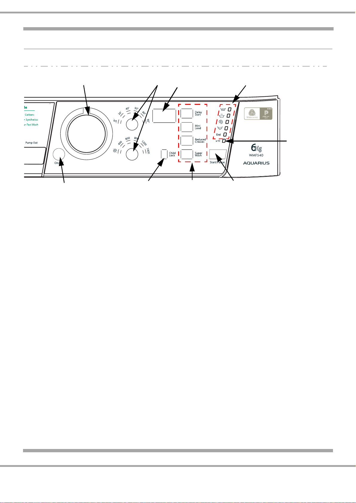
OPTIONS
Options are selected by pressing the button and confirmed by illumination an orange LED situated in
the button.
If an option is not available with a programme, the LED will flash and a bleeping noise will be heard
when pressing the button.
Delay Start
To set a delayed start for the selected wash cycle, press the button repeatedly until the desired delay
time is displayed [this may be between 1 hour and 24 hours].
To disable the function press the button until the text OFF is displayed.
N.B. Once you have pressed the START/PAUSE button, the delay time may only be decreased if you
wish to modify it. This option is enabled with all programmes.
Mini Load
This function is recommended for when the load of laundry is equal to half, or less than half, of the
maximum recommended load [see Table of wash cycles].
This function may not be used in conjunction with wash cycles 5, 11, 12, 13, B, C.
Reduced Creases
By selecting this function, the wash and spin cycles will be modified in order to reduce the formation of
creases. At the end of the cycle the washing machine will perform slow rotations of the drum; the
REDUCED CREASES and START/PAUSE indicator lights will flash [orange] and the END phase will
remain lit in a fixed manner. To end the cycle, press the START/PAUSE button or the REDUCED
CREASES button.
For the Silk [10] and Lingerie [B] wash cycles, the machine will end the cycle while the laundry is
soaking, the REDUCED CREASES and START/PAUSE indicator lights will flash [orange] and the
RINSE phase will remain lit in a fixed manner. To drain the water so that the laundry may be removed,
press the START/PAUSE button or the REDUCED CREASES button.
This function may not be used in conjunction with wash cycles 6, 9, 11, 12, 13, B, C.
Super Wash
Because a greater quantity of water is used in the initial phase of the cycle, and because of the
increased cycle duration, this function offers a high-performance wash.
This function may not be used in conjunction with wash cycles 5, 8, 9, 10, 11, 12, 13, A, B, C.
DELAY START
MINI LOAD
REDUCED CREASES
SUPERWASH