Hsun hs700atv User manual

1
700ATV Maintenance Manual

2
Catalogue
General Information……………………………...5
1 Description…………………………………………………..5
1.1 Identification code………..……………………………..6
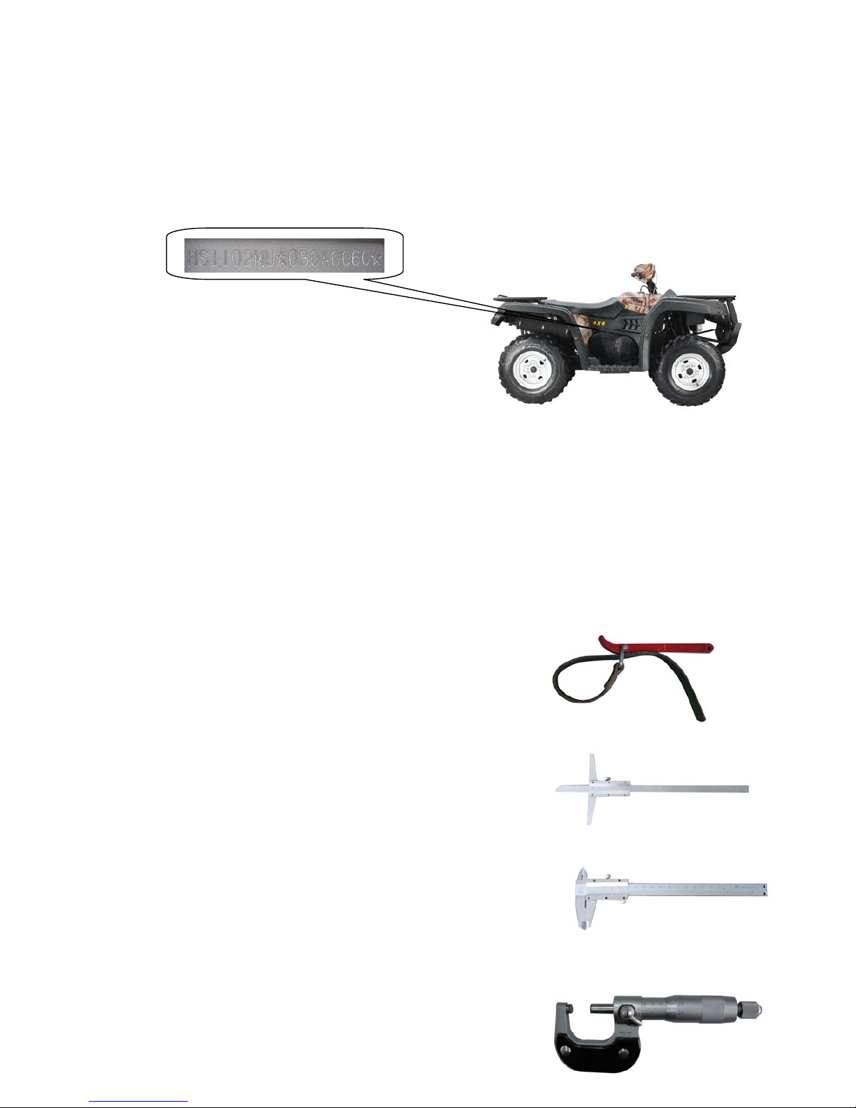
1.1.1. Frame No. …………………………………………………6
1.1.2. Engine No.…………………………………………………7
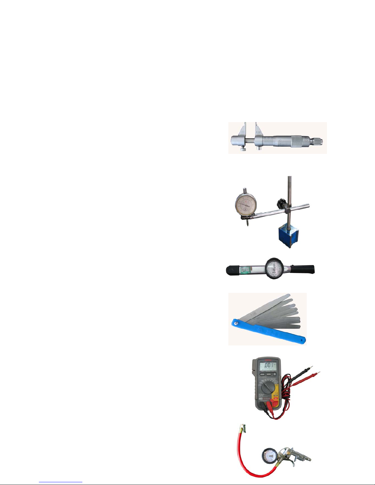
1.2 Special tools, instruments and meters…………………7
1.3 Periodic maintenance chart……………………………….9
Engine………………………………………………………….11
2. Inspection and adjustment of engine…………….11
2.1 Inspection of cylinder head, intake
and exhaust valve………………………………………….11
2.2 Inspection of spark Plug………………………………….12
2.3 Inspection of cylinder, piston and piston ring…….14
2.4 Inspection of crankshaft………………………………….17
2.5 Inspection of clutch……………………………………….18
2.6 Inspection of carburetor………………………………….18
2.7 Inspection of air filter………………………………….19
2.8 Inspection of oil filter………………………………….20
2.9 Inspection of lubrication system……………………….20
2.10 Lubrication of engine…………………………………….21
2.11 Inspection of cylinder head…………………………….21

3
3.Disassembly of engine……………………………………27
3.1 Cylinder head and block………………………………….27
3.2 Piston and connecting rod……………………………….31
3.3 Manual starting mechanism……………………………….32
3.4 Sensor………………………………………………….…….32
3.5 Left crankcase cover……………………………….…….33
3.6 Magneto…………………………………………………..….33
3.7 Oil pump………………………………………….……..….34
3.8 Clutch…………………………………………………...….35
3.9 Carburetor……………………………………………...….36
3.9.1 Structure of carburetor………………………...…..36
3.9.2 Inspection and adjustment of carburetor…....….37
4.Chassis
4.1 Steering operation system………………………...…..39
4.2 Brake system…………………………………………...….51
4.3 Wheels and tires……………………………………...….67
4.4 Transmission system…………………………….…...….70
4.5.gearshiftmechanism……………………………………..77
4.6 Suspension…………………………..……....….。。。。。.79
5. Electrical system………………………..……....….84

4
5.1 Ignition system…………………………..……....….87
5.2 Magneto and charging system…………..……....….88
5.3 Battery……………………………………..……....….88
5.4 Lighting system…………………………..……....….90
5.5 Meterand signal system…………………………..……91
5.6 Electrical starting system…………….……..…….92
6.Appendix………………..…………………..……....…93
6.1 Specification………..…………………..……....….93
6.2 Requirements for torque of fastener……………….99
6.3 Electrical circuits……………………………....….100

5
General Information
1. Description

6
1.1 Identification code
1.1.1. Frame No.
The frame No. is engraved in the right bottom of the supporting frame.
See Figure 1-1.
Figure1-1

7
1.1.2.Engine No.
The engine No. is engraved in the right side of the engine. See figure 1-2
Figure 1-2
1.2 Special tools, instruments and meters
1.2.1 Oil filter detacher
To fasten and detach the oil filter
1.2.2 Height gauge
To gauge the height of various components
1.2.3 Vernier
To measure the length of various components
1.2.4 Outside micrometer

8
To accurately measure external
diameter of a column
1.2.5 Inside micrometer
To accurately measure internal
diameter of a hole
1.2.6 Dial indicator
To accurately measure a small distance
1.2.7 Torque Spanner
To measure torque force
1.2.8 Feeler gauge
To measure gap-width
1.2.9 Multimeter
To check electrical circuits and parts

9
1.2.10 Barometer
To measure pressure of the tire
1.2.11 Magneto drawing device
To detach the magneto
1.2.12 Snap ring clampTo install
and detach snap rings
1.3 Periodic maintenance chart
EVERY INITAL
month 1 3 6 6 12
km 320 1,200 2,400 2,400 4,800
(mi) (200) (750) (1,500) (1,500) (3,000)
ITEM
ROUTINE
Whicheve
comes first
hours 20 75 150 150 300
Valves ● Check valve clearance.
●Adjust if necessary.
○○○○
Sparkplug
●Check condition.
●Adjust gap and clean.
●Rep;ace if necessary.
○○○○○
Air fiter element ● clean.
●Replace if necessary.
Every20-40hours
(More often in wet of dusty areas.)
Carburetor*
● Checkandadjustidlespeed/starteroperation.
● Adjust if necessary.
○○○○
Crankcase
breathersystem* ● Check breather hose for cracks of ○○○

10
damage.
● Replace if necessary.
Exhaust system*
● Check for lecakage.
● Tighten if necessany.
● Replace gasket(s) if necessary.
○○○
Spark arrester ● Clean. ○○○
Fuel line*
● Check fuel hose for cracks or damage.
● Replace if necessaly.
○○○
Engine oil ●Replace.(Wamenginebefore draining.) ○○○○
Engine oil filter
cartridge ●Replace. ○○○○
Engine oil strainer* ●Clean. ○○○○
Final gear oil
Differential gear oil
● Check for oil leakage.
● Replace eveny 12 months.
○
○
Front brake*
● Check operation/fuid leakage.(See NOTE
page 8).
● Correct if necessary.
○○○○○
Rear brake*
● Check operation.
● Adjust if necessary.
○○○○○
Select lever safety
system cable ● Check operation.
● Adjust if necessary.
○○○
V-belt*
● Check operation.
● Check for cracks or damage.
○○○○
Wheel ● Check balance/damage/ ○○○○

11
● Repair if necessary.
Wheel bearing*
● Check bearing assemblies for lossenss/
damage.
● Replace if necessary.
○○○○
Front and rear
suspendion*
● Check operation.
● Correct if necessary.
○○
Steering system*
● Checkoperation./Replace if damaged
● Check toe-in./Adjust if necessaly.
○○○○○
Drive shaft universal
joint*
● Lubricate with lithium–soap–bassed
grease.
○○○
Axle boots*
● Check operation.
● Replace if damaged.
○○○○○
Fittings and
fasteners*
● Check all chassis fittings and fastenrs.
● Correct if necessary.
○○○○○
Lights and
switches*
● Check operation.
● Adijust headinght beams.
○○○○○

12
Engine
2. Inspection and adjustment of engine
2.1 Inspection of cylinder head, intake and exhaust valve
Preheat the engine ,then misfire and unplug the spark plug.Fix
pressure gauge into the hole, open the choke and throttle handle,and start
for 4-6 times.
Note: Giving a leakage check to the pressure gauge.Rotate the
engine until the pressure gauge stop rising.The maximum
reading would be greater than 0.7-0.9Mpa after starting
for 4-6 times.
See figure 2-1.
Figure 2-1
check the valve lash
Note:when adjust valve lash,the engine must be cooled. (The
tempreture should be less than 35)
Remove the seat cushion and fuel tank,unplug the vision hole

13
cover ,round the flywheel of magneto anti-clockwise to aim “T”at the
signal of fore cover on the left.
Note: The piston must be fixed to the dead enter. (Figure 2-2)
Figure 2-2
Remove cylinder valve cover,check the lash between the valve stem
by feeler gauge .
Valve clearance:inlet and exhaust valve: 0.05~0.08mm.
See figure 2-3.
Figure 2-3
Loose the lock nut,rotate the adjusting screw until it appears that
the feeler gauge be pulled .Then fasten the adjusting screw by valve
adjuster,tighten the lock nut and check the valve lash .Afterword install
the cylinder valve cover , vision hole cover,the fuel tank and cushion.

14
See figure 2-4.
Figure 2-4
2.2 Inspection of spark Plug
1. Unplug the Spark-Plug cap:remove
the spark plug by box key,look over
whether the spark-plug insulator and
electrode is damaged or sooting.
If so ,see figure 2-5. Figure2-5
2.Check the spark clearance
by feeler gauge whether it
is between 0.6~0.7mm.Or adjust
the gap,clean incrustation
with spark-plug cleaner and steel
wire brush and check if
the spark plug sealing washer(Figure 2-6). Figure 2-6
.

15
3.Swirl the when spark plug and tighten to 18~20N.m by box key ,then
fix the spark plug cap when assembling.
2.3 Inspection of cylinder, piston and piston ring
Camshaft lube is injected by a hole of engine body into
cylinder ,so the hole must not jam.It is necessary to fix the cushion
and adjer without dust permeated into the crank case before assembly.
item standard value:mm limit value:mm
bore diameter of cylinder 102~102.03 102.1
taper 0.0040 0.005
out of roundness 0.0035 0.005
cylinder
degree of toruosity 0.04 0.06
external diameter of piston 101.95~101.97 101.92
bore diameter of piston pin
hole 22.002~22.010 22.010
gap between piston pin and
piston pin hole 0.007~0.020 0.02
Piston ring
end
clearance
Top ring/the
second ring
0.25~0.40 0.5
oilring 0.3~0.9 1.2
top ring 0.3~0.07 0.10
gap between
piston ring
and piston
groove the second
ring 0.02~0.06 0.09
gap between cylinder and
piston 0.03~0.08 0.09
Piston,piston
ring and
piston pin
external diameter of piston
pin 21.995~21.990 21.96
bore diameter 22.016~22.027 22.03
connecting
rod
Gap between small end of
connecting rod and piston
pin
0.016~0.033 0.035

16
diagnosing and eliminating of malfunction:
●Emission of black smoke for abrasion of cylinder or
piston,
1. Cylinder , piston of piston ring is worn out.
2.The piston ring is not properly assembled.
3. The piston or cylinder wall is scraped.
●overheated
1、Excessive incrustation of piston.
2、Blast and abnormal noise.
3、Abrasion of cylinder or piston.
Inspection of cylinder.
1.Check whether the cylinder is damaged.
2.Measure the bore diameter of cylinder at three spots.
3.At the top,the middle and the bottom of the piston stroke .And measure
the bore diameter at directions of right-angle intersection.
repairing limit value:
out of roundness: 0.005 mm
taper :0.005mm
Inspection of piston and piston ring
Measure the gap between piston ring and piston groove.
1.unplug the piston ring;

17
Note:It is forbidden to damaging the piston ring when
assembling.Check whether the piston and the piston groove is cracked
and abraded.See figure 2-7
Figure 2-7
2.Insert piston ring into
cylinder,and measure the
end gap.repairing limit
value:the first ring/the
second ring: 0.5mm
See figure 2-8. Figure2-8
Measure the bore diameter of piston pin hole.
repairing limit value: see figure 2-9
Figure 2-9

18
3.Measure the external diameter 10mm
above the bottom of the piston skirt.
Extreme position :the gap between
cylinder and pistonrepairing
limit value: 0.1mm See figure 2-10 Figure 2-10
Measure the external diameter of piston pin:
the gap between piston and piston pin:
repairing limit value: 0.02mm .See figure 2-11
Figure 2-11
2.4 Inspection of crankshaft
heck that whether crank and connecting rod can rotate without stuck
and whether the clearance between crank and connecting rod is 0.5~
0.6mm.The hop of crank shaft should be 0.05mm.If not so,replace it. See
figure 2-12-1, figure 2-12-2.

19
Figure 2-12-1 Figure 2-12-2
2.5 Inspection of clutch
The wear condition of shoe block and friction plate:See
figure 2-13
Figure 2-13
2.6 Inspection of carburetor
1、Inspect the idle of carburetor
The engine speed should be 1500±150r/min 10 minutes after starting
at normal idle and will not misfire when briskly accelerate.If not so,
rotate the carburetor idle adjusting screw clockwise to rise the idle ,anti-
clockwise to lower.When adjusting is unavailable,check that if there is a
jam in
carburetor idle nozzle or a
air-leakage of intake pipe.

20
See figure 2-14
Figure 2-14
2.7 Inspection of air filter
1、Disassemble the air cleaner,remove cartridge,clean the cartridge
with non-flammable cleaning solvent,and then make it dry.
Note: Petrol is forbidden.
2.Dip the air filter cartridge into 20# oil,then take it out and squeeze
the excessive oil,assemble it orderly.Impermeability is
necessary.See figure 2-15, figure 2-16.
Figure 2-15 Figure2-16
2.8Inspection of oil filter
Cleaning of lubricator oil strainer:remove clarifier (Figure
2-17),clean it to ensure a well work- condition.Then fix it up.
Note:Clean the clarifier
before injecting oil
Table of contents
Popular Offroad Vehicle manuals by other brands

Ski-Doo
Ski-Doo Mini Z Operator's guide

Yamaha
Yamaha KODIAK YFM700FWBD 2017 owner's manual

Yamaha
Yamaha FX Nytro FX10D owner's manual

Arctic Cat
Arctic Cat M 9000 King Cat Operator's manual

BOMBARDIER
BOMBARDIER SKI-DOO MX-Z Renegade 600 HO SDI Operator's guide

Polaris
Polaris Ranger 4x4 500 EFI 2007 owner's manual