HZ Sound Systems Qmix User manual

6 CHANNEL 1U Hi RACK MOUNT AUDIO MIXER
OWNERS MANUAL
For EUROPEAN220V -230V
OPERATION
Hz INTERNATIONAL LTD COMBE HOUSE - STOKE ST MICHAEL -BATH - SOMERSET – ENGLAND

UNPACKING
Although the Q – Mix has been designed as a rugged piece of professional equipment, it is quite heavy for its size. It contains a high specification
modern electronic PCB assembly and should be treated with care.
The packaging of the unit is specifically designed to safely transport this product. In the unlikely event of the product requiring servicing, this
packaging is the safest way to transport it.
All units are factory set for 220-230v operation. Units factory made for 110/120V supply are clearly marked on the back and should not be
connected to any higher voltage power source.
FITTING A POWER LEAD PLUG
The wires in the IEC/CEE mains lead are coloured: Earth: Green/Yellow Neutral: Blue Live: Brown
MOUNTING THE UNIT
This unit has been designed for rack mounting use, in a Racking enclosure made to BS5954, IEC297 or Din 41494 standards.
It must be mounted in the horizontal position with clear cool air flow of 5cm around the side air vents.
DO NOT USE RACKS NEAR HEATING DUCT OUTLETS, APPLIANCES OR RADIATORS.
Care is required when installing these units in a rack. It is advisable to put the Rack on its back, then place all the other equipment being fitted
to the rack into it before tightening the retaining screws.
Contents:
1. OVERVIEW
2. USING THE Q-MIX
3. SPECIAL FEATURES
4. REAR CONNECTIONS
5. TROUBLE SHOOTING

OVERVIEW
PA SPEAKERS MONITORS
KEYBOARDS MICROPHONES
EFFECTS PROCESSOR TURNTABLES
CD or DVD PLAYERS
SUB BASS
BASS AMP
POWER AMPS
INSTRUMENTS

Using the Qmix
Input Channels 1 – 4
The Mic Inputs
The mic input of these ‘combi sockets’ requires XLR-type connectors and are designed to suit a wide
range of BALANCED or UNBALANCED signals. Professional dynamic, condenser, or ribbon mics are
best because these will be LOW IMPEDANCE. You can use low-cost HIGH IMPEDANCE mics, but the
level of background noise will be higher. If you press the PHANTOM POWER 48V switch at the rear of
the Q-mix all the XLR inputs will receive a suitable powering voltage for professional condenser mics.
A. = Unbalanced Male XLR B. = Balanced Male XLR
ONLY connect condenser microphones with the 48V power OFF (switch OUT), and ONLY
turn on the 48V with the input gain DOWN; this will prevent damage to the mixer and
external equipment.
TAKE CARE when using unbalanced sources, which may be damaged by phantom power
voltage on pins 2 & 3 of the XLR connector
Unplug any mics if you want to use the LINE input. The input level is set using the GAIN knob.
The Mono Line Inputs
The centre hole in the ‘combi socket’ accepts 3-pole ‘A’ gauge (TRS) jacks. Use this high impedance
input for sources other than mic, such as keyboards, sound modules, and guitars., etc.
The input is BALANCED for low noise and to give high quality from professional equipment, but it can be
used for UNBALANCED sources by using the wiring of the jacks as shown, although it is advised that the
cable lengths be as short as possible.
C. = Unbalanced (TRS)Jack Plug D. = Balanced (TRS)Jack Plug
A.
B.
C. D.

The Controls Channels 1 - 4
The Gain Knob
This knob sets how much of the source signal is sent into the mixer. Too high and the signal will distort as it overloads the channel. Too low, and
the level of background hiss will be more noticeable and you may not be able to get enough signal level to the output of the mixer.
Setting the knob at 9’oclock gives approximately unity gain for the LINE input. Note that some sound equipment that is intended for domestic use,
operates at a lower level (-10dBV) than pro-audio gear and will therefore need a higher setting to get the same level.
Each channel features a RED peak level LED, this is set show at 0dB (0.775v) and is designed to indicate the onset of clipping (distortion), however
occasional flashing of this will be observed from very dynamic sources, without causing any undesirable effects.
FX Level Knob
This knob is used to control the level of the signal going to the effects send mixing bus.
It is POST EQ & POST VOLUME, if the Channel Volume or the Eq is adjusted, then the level of signal going to an effects processor will also be
changed.
Volume Knob
Use this to balance the mix & level of signal going to the Master Mixing Stage and outputs.
Tone Controls (EQ)
The 3 Band equaliser (EQ) section allows good manipulation of the frequency bands. It is particularly useful in live PA applications where the
original signal is far from ideal and where boosting and cutting of the right frequencies can dramatically improve the quality of the performance.

Bass Control
Turn knob clockwise to boost low (bass) frequencies (100Hz and below) by up to 15dB, for adding warmth to vocals, or extra punch to keyboards,
sound modules, guitars. etc. . Turn the knob
anti-clockwise to cut bass frequencies by up to 15dB, reducing hum, stage rumble, or improve a mushy sound. Set the knob at the 12 ‘o clock
position for a flat response.
Mid Control
The mid band is the most difficult control to use correctly in an eq, as it covers the active frequency range of most vocals, string and wind
instruments. etc. To add mid tone turn the knob clockwise
to give up to 15dB gain between (240Hz – 6kHz). Beware too much mid can make for a honky sound and can cause feedback. Turn the knob anti-
clockwise to cut mid the tones by up to 15dB. Set the knob at the 12 ‘o clock position for a flat response.
Treble Control
Turn clockwise to boost high (treble) frequencies (10kHz and above) by up to15dB, to add crispness and brightness to your sound. Beware if you
have a noisy (hissy) signal source then the use of too much treble could increase your background noise level. Turn anti-clockwise to cut
frequencies by up to 15dB, reducing hiss or excessive sibilance. Set the knob at the 12 ‘o clock position for a flat response.
Input Channels 5 –6 (Stereo)
The Stereo Line Inputs
These two stereo channels are accessed through the dual RCA phono sockets or the dual
jack
2-pole ‘A’ gauge (TRS) jacks, all these inputs are UNBALANCED. All jack inputs are
switched, so that if only 1socket is used then the signal is automatically fed into the other
side.
The sensitivity of these channels has been designed for use with Tape, CD, Mini Disk, DAT,
and DVD players, however they can be used for keyboards, sound modules, and synths. etc.
Use of the Mic Channel 4, will cause both of these channels to ‘DUCK’ (Auto Fade) if the
TALKOVER button is selected at the rear of the Qmix. This feature is ideally suitable for MC,
DJ, KARAOKE & CONFERENCING applications.

FX Level Knob
This knob is used to control the level of the signal going to the effects send mixing
bus. It is POST EQ & POST VOLUME, if the Channel Volume or the Eq is
adjusted, then the level of signal going to an effects processor will also be changed.
Volume Knob
Use this to balance the mix & level of signal going to the Master Mixing Stage and
outputs.
Bass Control
Turn knob clockwise to boost low (bass) frequencies (100Hz and below) by up to 15dB, for adding depth to recordings, or extra punch to keyboards,
sound modules, etc.
Treble Control
Turn clockwise to boost high (treble) frequencies (10kHz and above) by up to 15dB, to add crispness and brightness to tracks. Beware if you have a
poor signal source then the use of too much treble will increase the noise level.
Master Controls
Monitor Volume Control
This knob is used to control the level of the signal going to the Monitor Output jack
at the back of the mixer, and can also be used as a ‘mono sum’ output. It has been
designed for monitor (foldback) for the artist or user to hear exactly what is
happening ‘on stage’, as in most applications they are situated behind the sound
system.
Master Volume Control
Does exactly what is says on the tin - it controls the overall Left & Right Output
Levels of the Qmix.

Contour Control
A pseudo Master Graphic EQ; turning this knob clockwise produces the infamous ‘smile’ curve,
that most users prefer. Fully clockwise will produce a really deep bass and a give very bright top end.
Vocal Boost Switch
Selection of this function will give 8dB shelving lift to frequencies at around 2.5kHz, this has been
designed liven up the upper mid vocal range. This can also be used to bring back the vocal presence,
if too much (‘smile’) on the contour control is used.
Rear Connections
To get the most out of your system, It is important to have the right connections so please check to make sure all of your hook up cables are correct
and you are using the right type of cable.
Channels 1- 4 = Microphone input = Male XLR
Combi-Socket = Line Level input = 3-pole ‘A’ gauge
(TRS) jacks
Channels 5 & 6 = Stereo Line input A = Dual RCA Phono
= Stereo Line input 8 = 2-pole ‘A’ gauge (TRS) jacks
Effects Send = 2-pole ‘A’ gauge (TRS) jacks
Effects Return = 2-pole ‘A’ gauge (TRS) jacks
Mixer to Mixer Link = Output = 5 pin Din
= Input = 5 pin Din
Monitor Output = 2-pole ‘A’ gauge (TRS) jacks
Sub Bass Output = 2-pole ‘A’ gauge (TRS) jacks
Main Output Left = 2-pole ‘A’ gauge (TRS) jacks
Main Output Right = 2-pole ‘A’ gauge (TRS) jacks
Mains AC input = 3 pin IEC
Contour Pseudo Graphic Equaliser
100Hz 500Hz 1k 5k 10k
Vertical Calibration @ 5 dB per div
MONO (TRS) JACK
STEREO (TRS) JACK
3 PIN MALE XLR
5 PIN DIN to DIN
RCA PHONO

Special Features
Despite it small size the Q-mix has some features usually found on ‘Desk’ type units.
Talk Over
To select depress the button marked TALKOVER at the back of the mixer.
This feature will ‘DUCK’ (Auto Fade) both Channels 5 & 6 (Music or Film track Audio
etc), when talking into a microphone in Channel 4 and is generally useful for MC, DJ,
KARAOKE & CONFERENCING applications.
The recovery time can be changed by a small pre-set mounted inside the mixer on the
back PCB, it is recommended that this adjustment should be made by your dealer or
an electronics engineer.
Phantom Power 48V
By pressing the PHANTOM POWER 48V switch at the rear of the Q-mix, XLR Mic Channels 1 – 4 will receive a suitable powering voltage for
professional condenser mics.
PLEASE NOTE THE GUIDE LINES GIVEN ON PAGE 3 OF THIS MANUAL REGARDING THE USE OF THE 48V PHANTOM POWER
Mixer to Mixer Link
This feature has been created, so that several mixers be linked together to provide a muti-channel 12 or 18 channel mixer in only a 2 or 3U rack
space. It can be to easily linked into the Q-zone our 6 channel zoner via this link. The pre-master stage 6 channel sub mix bus left & right +effects
send & return are passed through this link, so that the receiving mixer can become the master control.
However if you make a return link, then all mixer masters will have the same programme – this means
multiple outputs etc., This could be used to feed different zones or monitor mixes, the choice is yours !.
Standard screened 5pin Din to 5pin 180º audio link leads are recommended for this application.
The pin connections are shown across the page.
Sub Bass Output
Today many modern sound systems use separate sub bass units, so we have included a special output feed for this application. Left & Right
outputs are summed into a 2nd order (12dB per oct) 120Hz low pass filter network.
INPUT DIN OUTPUT DIN
3 1 FX in 3 1FX out
Left 5 4 Right Left 5 4 Right
2 2
Screen Screen
View looking into sockets

Trouble Shooting
Although the greatest care has been taken in the manufacture of this mixer, the possibility remains that faults could occur during use or difficulties
could be experienced during initial installation.
The cause, however, will rarely be found to be internal to the be the mixer. Below is a list of symptoms and possible causes. Some of the
suggested causes may appear obvious , but they can be easily overlooked.
Under no circumstances should you open the mixer; as this is dangerous, and will expose you to mains voltages; it will also invalidate all rights
under the guarantee.
1. After turning on the 'power' switch the 'power' indicator does not light-
The mains plug is not pushed far enough into the mixer.
Check there is a supply to the mains socket.
Check supply using an alternative electrical appliance.
The mains input fuse is broken, at back of mixer, replace using QB 250mA 20mm fuse.
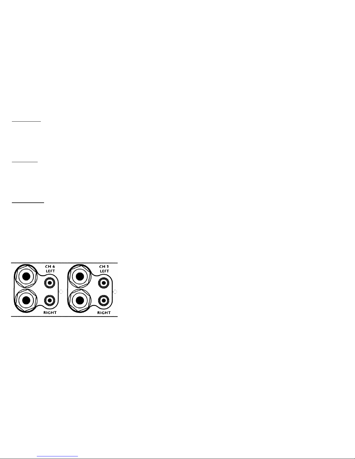
2. When the controls are advanced no sound is heard-
Check the input signal is connected to input socket.
Check the input signal is connected to channel being used
Move input plug to another channel, or use controls on connected channel.
3. Even when the output is low, the output sounds distorted-
Check the input gain is not too high - peak LED will be on
Check the input signal is not too high - peak LED will be on
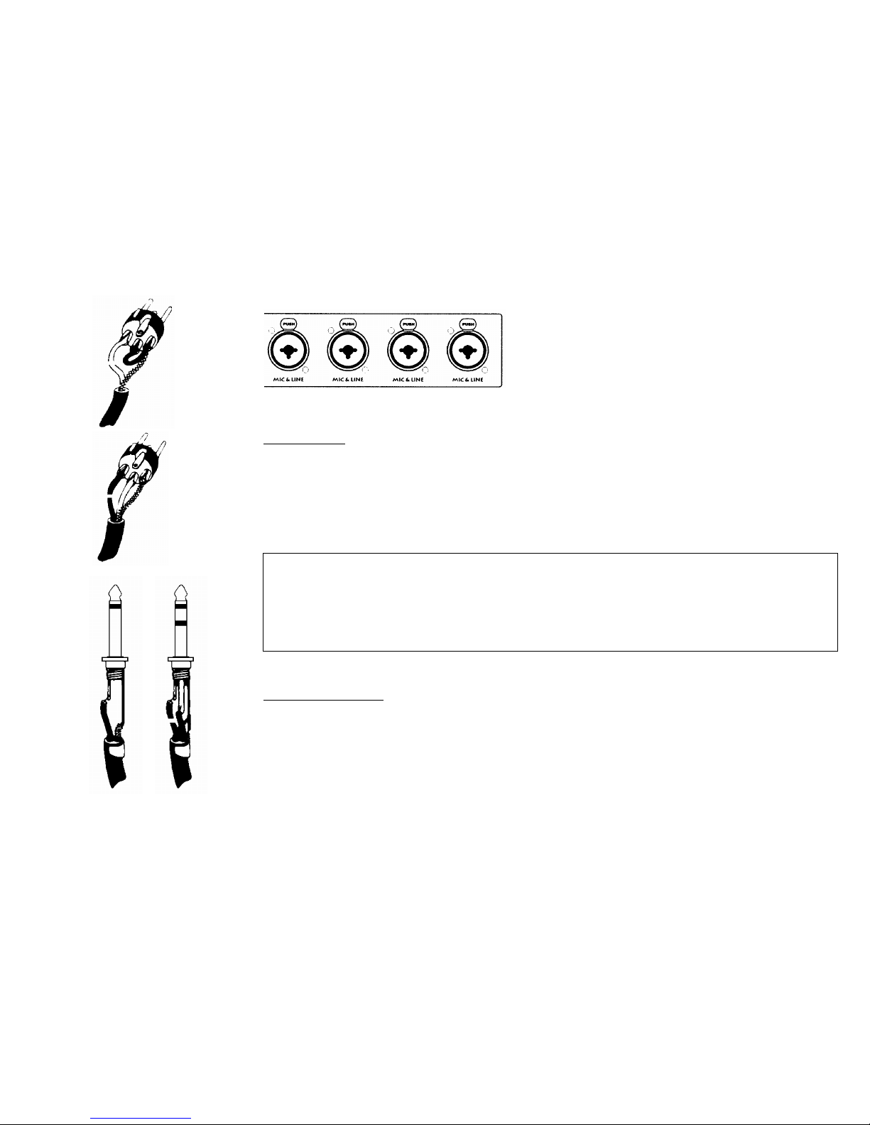
4. Condenser mic not working
Check the 48 phantom power on
Check the mic is plugged into a mic channel 1 – 4 only
Check the mic cable a balanced 3 wire type
As a general rule jack plugs and sockets are very reliable especially if they are regularly connected and disconnected. In situations where they are
subject to prolonged static use - it is good practice to clean the plugs and to clean the sockets by taking a new plug and waggling it in & out. this
will stop any build up of any corrosion.
DO NOT
SWITCH or LINK + & - TERMINALS
IF IN DOUBT CALL HELP LINE
PLEASE REMEMBER YOUR SYSTEM IS
ONLY AS GOOD AS ITS WEAKEST POINT
THIS IS GENERALLY
THE HOOK UP WIRES
NEARLY ALL SOUND SYSTEM
FAULTS CAN BE TRACED BACK
TO POOR WIRING CHECK
ALL YOUR CABLES REGULARLY
HELP LINE (UK) 44 1749840102

GUARANTEE
YOUR EQUIPMENT IS GUARANTEED FOR A PERIOD OF TWELVE MONTHS TAKEN FROM THE DATE OF PURCHASE OF THE PRODUCT
AGAINST ANY DEFECTS DUE TO FAULTY MATERIALS OR FAULTY MANUFACTURING. DURING THIS PERIOD, REPAIRS TO THE
EQUIPMENT WILL BE CARRIED OUT WITHOUT CHARGE FOR LABOUR OR MATERIALS BY ANY AUTHORISED DEALER OR THE
FACTORY SUBJECT TO THE FOLLOWING CONDITIONS.
1. The fault must be entirely due to faulty materials or faulty manufacture.
2. The defect must not have been caused by bad installation, accidental damage, misuse or failure to comply with the instructions given in this
users manual.
3. The equipment must be used solely for audio applications and is subject to fair wear and tear, for commercial usage.
4. If at any time during the guarantee period part or parts of the equipment are replaced with a part or parts not supplied or approved by us or if the
equipment has been dismantled or repaired by any person not authorised by the us, then guarantee shall immediately cease and become void.
5. Evidence of the date of purchase (invoice, receipt or finance agreement) must be produced at the service department to obtain the benefit of this
guarantee. Any carriage charges relating to the guarantee will be the responsibility of the purchaser.
6. This guarantee applies to the original purchaser only and the equipment must have been purchased or financed from new, the guarantee cannot
be assigned or transferred.
7. Any defective part that has been replaced shall become the property of the company and the right is reserved by the company to replace the
equipment or repair it at the option of the company.
8. This guarantee applies to equipment purchased and used within the E.E.C. The importers of equipment in non E.E.C. countries are responsible
for the guarantee of this equipment. Parts required under guarantee are free. Shipping charges for components will be charged at cost.
9. Knobs, potentiometers, switches and chassis mount connectors are not covered under the terms of this guarantee.
10. The guarantee does not cover equipment that is in industrial use or which are the subject of rental or hire agreement.
11. The guarantee shall become void if the equipment is at anytime used on any supply circuit or voltage range other than that specified on the
equipment.
12. THIS GUARANTEE DOES NOT IN ANY WAY AFFECT YOUR STATUTORY RIGHTS AS A CONSUMER WITHIN THE E.E.C.

THE INFORMATION CONTAINED IN THIS MANUAL IS CORRECT AT THE TIME OF GOING TO PRESS, HOWEVER IN LINE WITH HZ’S
POLICY OF CONTINUAL DEVELOPMENT SOME OF THE DETAILS MAY CHANGE ON FUTURE MODELS.
E & OE
Table of contents