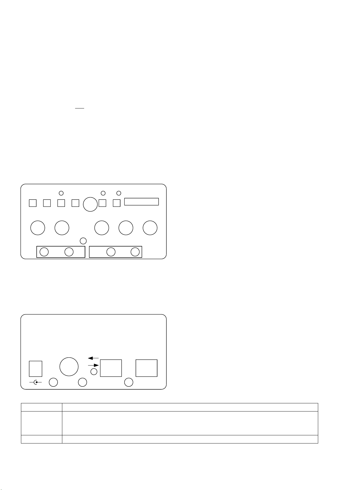
G8NJJ Audio Mixer and Recorder
This unit allows two operators to use amateur radio transceivers for contest or field day operations. It allows PC type
headsets with boom microphones; one operator can transmit but both can hear each other. Its features include:
Two microphone inputs, with individual gain controls
Two identical headset outputs (note no volume control –use the headset volume control)
Select switch to choose which microphone is routed to the transmitter
TX level control, to set “mic gain” on radios with no separate adjustments
RX level control, to set a comfortable radio receive signal level
Internal speaker for RX audio, with volume control
VU meter to equalise signal levels for the radio TX path
Audio recorder, for recording & replaying “CQ” type calls
PTT button, with latch
About the Unit
Each microphone input has its own preamplifier, and a bias circuit for the electret microphones found in PC
headsets. The bias can be disabled by removing an internal jumper. Channel 2 can have the microphone input
provided by a handheld microphone, selected by the rear panel switch. The audio mixers are all “virtual earth”
mixers created using simple operational amplifier circuits. The audio recorder uses an ISD1760PY audio recorder IC;
the simplest way to buy these is to buy a PCB on ebay and throw away the PCB. The VU meter uses a simple LM3916
LED display driver.
The major design challenge was getting all of the controls into a front panel. In the end I chose a two PCB solution,
with the audio path on one PCB and the recorder and VU meter in the other. The main audio board was too complex
for a homebrew PCB, so I had a batch of 5 made in China, very cost effectively. The VU meter and recorder were
made as a homebrew PCB, but if I made more I’d make some of the PCB pads a little larger.
The whole fits an extruded aluminium box, making a compact unit. The front and rear panels have laser-printed
legends, making an attractive end product. By far the longest mechanical activity was drilling the holes for the
speaker: on reflection, cutting out an oval hole might have been faster.
Operation
Mixer
The unit mixes audio to the headsets from the radio, both microphones and the audio recorder. The radio input is
stereo, for those radios that have two independent receivers (e.g. for dual polarisation antennas). “RX in Vol” adjusts
the RX audio input level.
The speaker output does not replay the microphone audio. This minimises opportunity for audio feedback.
The unit has been designed for two operators, with only one operating the transmitter. Both operators can hear
each other. The front panel switch selects which one is connected to the transmitter.
Audio Recorder
The audio recorder permits for repetitive “CQ” type calls. It is capable of recording around 30 seconds of audio. Each
time “play” is pressed, the stored message is played; the unit can key the PTT at the same time.
“ERASE” erases the current recorded message. If pressed for around 3 seconds it will erase all messages. The
green Led will flash 7 times when that happens.
“NEXT” skips to the next recorded message. If on the last one, it will skip to the start.
“RECORD” records a new message while it is pressed. The front panel microphone is used for record audio.
“PLAY” plays the current message.