ICON aio 6 User manual

N1630
USBMIDI/Audiocontrolsurface

ARNING: To reduce the risk of fire or electric shock, do not expose this unit to
rain or moisture
Important SafetyInstructions
. Read this manual thoroughly before using this unit.
2. Keep this manual for future reference.
3. Take notice of and comply with all warnings included in the user's manual or indicated
on the appliance.
4. Follow all instructions included in this manual.
5. Do not expose this unit to rain or moisture. Avoid having water or other liquids spilled
on this unit.
6. When cleaning the cabinet or other parts of this appliance, use only a dry or slightly
damp soft cloth.
7. Do not block any ventilation openings or interfere with the proper ventilation of this unit.
Install in accordance with the manufacturer's instructions.
8. Do not use or store near any heat sources such as radiators, heat registers, stoves, or
other heat-producing appliances.
9. Do not interfere with the safety purpose of the polarized or grounding-type plug. A
polarized plug has two blades with one wider than the other. A grounding-type plug h
as two blades and a third grounding prong. These are designated for your safety. If the
provided plug does not fit into your outlet, consult an electrician.
0. Protect the power cord from being walked on or otherwise damaged by items placed
on or against them. Particular attention should be given to the plugs, receptacles, and
the point where the cord exits the appliance.
. To avoid the risk of electrical shock, do not touch any exposed wiring while the unit is
in operation.
2. Only use attachments/accessories specified by the manufacturer.
3. Unplug this unit and all connected electrical equipment during lightning storms or when
left unused a long period of time.
4. Refer all servicing to qualified service personnel. Servicing is required when the
appliance has been damaged in any way or fails to operate normally.

Contents
Introduction
Features
Top Panel Layout
Getting Started
What's in the package
Connecting your aio6 controller
Left Side Panel Layout
Right Side Panel Layout
Rear Panel Layout
Mac driver installation
Software control panel
indows driver installation
Software control panel
Software control panel (continued)
Map Software for Mac OS X
Installing iMap Software for indows
iMapaio software panel
Firmware upgrade
Restore the factory default settings
Hardware Connections
Minimum System Requirements
Specification
Services
iTM
TM
TM
2
1
1
3-5
6
9-10
11
14-15
15-17
18
6
7
8
12-14
18-19
20-21
22
22
23
24
24-25
26

Introduction
Please write your serial number here for future reference:
Purchased at:
Date of purchase:
Thank you for purchasing the ICON aio6 Midi/Audio control surface. We sincerely
trust this product will provide years of satisfactory service, but if anything is not
to your complete satisfaction, we will endeavor to make things right.
In these pages, you'll find a detailed description of the features of the aio6, as well
as a guided tour through its front and side panels, step-by-step instructions for its
setup and use, and full specifications.
You'll also find a warranty card enclosed - please don't forget to fill it out and mail
it so that you can receive online technical support at: www.icon-global.com. And
so we can send you updated information about these and other ICON products in
the future. As with most electronic devices, we strongly recommend you retain the
original packaging. In the unlikely event the product must be returned for servicing,
the original packaging (or reasonable equivalent) is required.
With proper care and adequate air circulation, your aio6 will operate without any
trouble for many years. We recommend that you record your serial number in the
space provided below for future reference.
What's inthe package?
aio6 MIDI/Audio control surface music production
Driver Software CD / Manual / Quick Start Guide
USB 2.0 cable

Features
24-Bit 96/ 92KHz 6-In/6-Out USB Recording Interface
4x4 analog I/O full duplex recording and playback
Dual MIC/Instrument preamps with individual gain control and phantom power switch
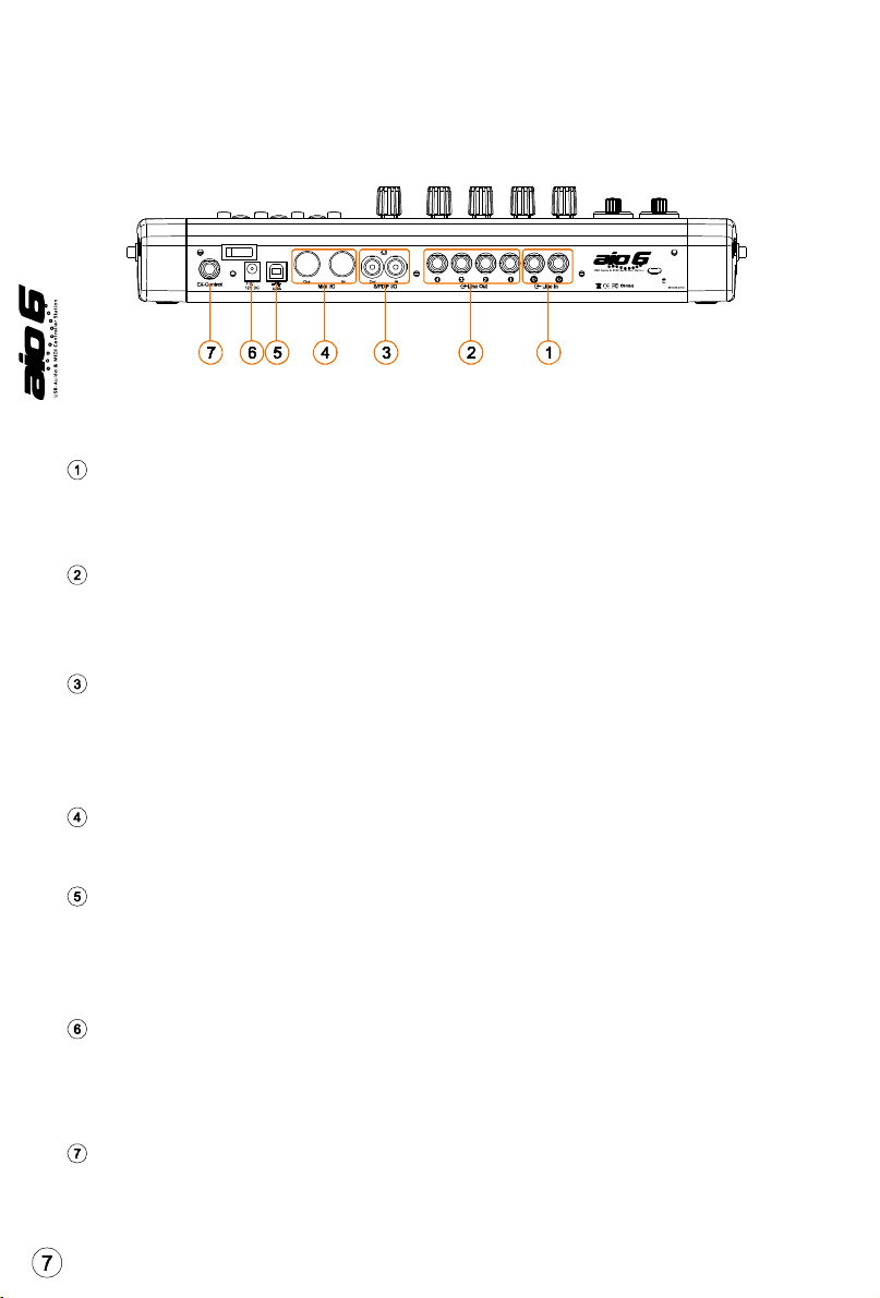
2 analogue line inputs on /4” TRS jacks
4 analog outputs on /4” TRS jacks
S/PDIF I/O on RCA coaxial connectors
x – 6 channel MIDI I/O
2- faders volume controls on the front panel
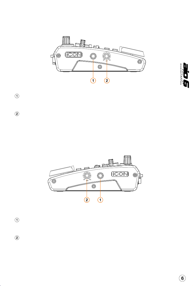
2 headphone output with channel /2 & 3/4 selectable switches and individual volume control
Flexible channel routing via the software control panel
4-channel faders plus one master channel fader
5 encoder knobs
Jog wheel shuttle for fast search and control
Illuminated buttons for each channel including Rec-enable, Solo and Mute
Illuminated “Channel/Bank” with “Up/Down” buttons for shifting channel by track or page
6 illuminated transport buttons including Play, Stop, Rec, Rewind, Fast forward and Loop
2-Illuminated Zoom keys for L/R & Up/Down
2-Illuminated Marker keys for Prev/Next & Up/Down
4-illuminated keys for Mixer, Edit, Save and Undo functions
2-illuminated “MK mode” buttons for shifting layer & 2 in Mackie Control mode
2-illuminated “User mode” buttons for shifting layer & 2 in user self define mode
Ex-Control connector for connecting up to 3 external control pedals (Optional
EC-3 splitter cable and SPD-0 pedal are needed)
USB 2.0 high speed connectivity
Supports DirectSound, WDM and ASIO2.0
Class-compliant with Windows XP, Vista (32-bit), Windows 7 (32-bit & 64-bit),
and Mac OS X (IntelMac)
Full duplex, simultaneous record/playback
Mackie control build-in for Cubase, Nuendo, Samplitude, Logic Pro and Abelton Live.
Mackie HUI protocol build-in for Pro Tool.
Robust aluminum and metal casing with Kensington lock port

3-segment LED display
“Mic/Inst” inputs 1/2
Input gain level controls 1/2
48V phantom power switch
Channel 1/2 & 3/4 switch for HP monitor 1
Channel 1/2 & 3/4 switch for HP monitor 2
The 3-segment LED display shows the parameter values as you adjust them and
also provides feedback about channel selections, operating modes, and more.
Unbalanced instrument and mic level inputs. These hybrid connectors will accept
a standard 3-pin XLR plug or a /4” TS connector.
These potentiometers control the input level of their associated analog Mic/Inst
/Line input.
Press to supply +48V phantom power to the associated XLR input. This phantom
power circuit is suitable for most condenser microphones.
Switch to select output channel /2 or 3/4 to be listened on HP monitor .
Switch to select output channel /2 or 3/4 to be listened on HP monitor 2.
Top Panel Layout
Note:ThefunctionoperatesslightlydifferentlybetweenDAWs.Pleaserefertoyour
DAWmanualforeachfunction.Thefollowing descriptionisbasedon thefunctions
thatoperateinSteinbergCubase.
TM

Output channel 1/2 volume fader
Output channel 3/4 volume fader
Slide to adjust the output level of output channel /2.
Slide to adjust the output level of output channel 3/4.
Knobs
Control buttons
REC buttons -
SOLO buttons -
MUTE buttons -
SEL buttons -
Channel faders
Master fader
Channel/Bank and Up/Down buttons
The five rotary encoder knobs are generally used for controlling the track pan
position, aux send levels and EQ of your DAW. You may also preset them to
adjust specific parameters within plug-ins and virtual instruments.
Activate and deactivate the recording state of the associated
channel. The switch will light red when the channel is armed.
Turn On and Off the solo state of the associated channel. The
switch will light green when the channel solo state is on and other channels
will be muted. You could solo multiple channel by pressing SOLO buttons on
additional channels.
Activate and deactivate the mute state of the associated
channel. The switch will light blue when the channel is muted.Mute the channel.
The SEL buttons activate the associated channels in the DAW
software in order to perform a specific operation (for example, when adjusting
EQ with the ASSIGNABLE ENCODERS, the SEL switch will be used to choose the
channel you want to adjust). When a channel is selected, the associated SEL
switch's red LED will light up.
These four programmable faders slide up and down to adjust linear MIDI
parameters such as volume.
This 60mm fader operates the same as the other 4 faders. It controls your DAW
software's master channel fader.
Activate the “Channel/Bank” button (red light) to shift channel by page or
deactivate it to shift by track. The “Up” and “Down” buttons are used for
shifting up and down.
Recording channelcontrolbuttonssection

In Mackie mode, press these two buttons to toggle between layers & 2.
In user-defined mode setting, press these two buttons to toggle between
layers & 2.
Activate the play function of the DAW.
Activate the stop function of the DAW.
Activate the record function of the DAW.
Activate the rewind function of the DAW.
Activate the fast forward function of the DAW.
Activate the loop function of the DAW.
Press this button to launch the mixer window of the DAW.
Press the Edit button to activate the edit function of the DAW to edit your project.
Press the Save button to activate the save function of the DAW to save your project.
Press the Undo button to activate the undo function of the DAW.
Activate “L/R” button and rotate the jog wheel to zoom left and right. Activate
“Up/Down” button and rotate jog wheel to zoom up and down at your DAW.
Activate “Up/Down” button and rotate the jog wheel to browse and select the
tracks. Activate Prev/Next button and rotate the jog wheel to scroll between
the marked points.
The jog wheel is used for various purposes specific to the DAW application,
including shuttle and scrubbing functions.
MK mode layer buttons
User mode
Transport control buttons section
PLAY button -
STOP button -
REC button -
REIND button -
FAST FORARD button -
LOOP button -
Mixer button
Edit button
Save button
Undo button
Zoom L/R & Up/Down buttons
Marker Up/Down & Prev/Next buttons
Jog wheel
Note:Youmustsetup yourownmidimappingforall thecontrolbuttonsand fadersetc.in
Usermode.

Left Side Panel Layout
HP Monitor 1 output
HP Monitor 1 volume control
This output jack accepts a standard /4" stereo TRS headphone connector.
This potentiometer controls the output level of HP Monitor .
Right Side Panel Layout
HP Monitor 2 output
HP Monitor 2 volume control
This output jack accepts a standard /4" stereo TRS headphone connector.
This potentiometer controls the output level of HP Monitor 2.

Rear Panel Layout
Line inputs 3/4
Line outputs 1-4
S/PDIF coaxial I/O connectors
MIDI I/O connectors
USB 2.0 Connector
12V/5A power adaptor
EX-Control pedal connector
These are unbalanced analog inputs on standard /4 TS connectors at
–0dB line level.
These are unbalanced analog outputs on standard /4 TS connectors at
+6dBU line level.
S/PDIF digital input and output on coaxial RCA connectors. The digital input
is selected via the aio6's software control panel, while the digital output
will be sent to the coaxial.
MIDI input and output on standard 5-pin DIN connectors
Connect it with the provided USB cable to your Mac/PC's USB connector.
Your Mac/PC must have a USB2.0 connector in order to run the full speed
of aio6.
Connect the provided power adaptor here.
This jack is able to connect up to 3- ICON foot pedals SPD-0 to activate
your selected functions.
Optional EC-3 splitter cable is needed if 3 pedals are using)
(Note:aio6isnotabletoworkwithouttheprovidedpoweradaptorconnected.
TheUSBbuspowerisnotabletoprovidesufficientpowersupplyforaio6.)
(

iCONAIO Ver1.00
iCONAIO Ver1.00
GettingStarted
Connectingyouraio6controller
Install aio6 driver on your Mac/PC. For installation details, please refer to pg. 9.
(Note:Pleasedo notconnectyouraio6toyourMac/PCbefore you haveinstalledthedriver.)
Connect the aio6 to your Mac/PC via the USB port.
Choose a USB port on your Mac/PC and insert the wide (flat) end of the USB cable.
Connect the cable's other end to the aio6. Your Mac/PC should automatically
“see” the new hardware and notify you that it is ready to use.
Setup your DA
Activate the ICON aio controller in your
DAW or MIDI software using “MIDI setup”
or “MIDI devices”.
For Cubase and Nuendo, choose Mackie
Control at the “Device List”.
TMTM
(Note:Everyapplicationdoesthisalittle
differently,so refertoyoursoftwareuser
manualforthesettings.)
Setup your audio settings
Select ICON ASIO driver on your DAW.
Computer(MAC or PC)
USB
Power Adaptor

Mac driver installation
Please follow the step-by-step procedures below to install your aio6 USB
recording interface and its driver.
Turn on your Mac
(Note:Donotconnecttheaio6digital
audiointerface toyourMacyet)
Insert the Driver CD into your CD-Rom.
After you have inserted the provided Driver
CD into your CD-Rom, a pop-up window
should appear as shown in Diagram , then
click on the"Mac” folder to open the
installation files list. Click “ICON_aio.mpkg”
elcome Screen appears
Choose "Continue" when you see the
Welcome Screen shown in Diagram 3
Set install location
Click the "Change install location” button
if you would like to set your preferred install
location, otherwise click the “Install” button.
Diagram 1
Diagram 2
Diagram 4
aio.mpkg
aio.CPL
aio.SPY
Diagram 3
aioDriver
aio
aio Driver
Installation start
The driver installation has started, please wait
until the process has completed.
aioDriver
aioDriver
Diagram 5

Installation completed
The driver installation has completed
successfully. Click the “Close” button.
Copy the software
control panel shortcut
logo to your desktop
Open the previous “Mac”
folder. Copy the 'aio”
software panel shortcut
logo and paste it to your
desktop.
Launch the software control panel
Click the aio's software control panel
shortcut logo you have just copied to your
desktop to launch thesoftware control panel.
Audio MIDI setup
Open the “Audio MIDI setup” window and
check if the aio device has setup properly
as shown below in diagram 9. If your aio
device does not appear on the system settings.
It means the driver did not install properly, go
through the “Driver Installation” procedure
again.
Diagram 7
Diagram 6
VGIG
.
aio
VGIG
.
aio.mpkg
aio
Diagram 8
aio
Diagram 9
aio
aio
aio
aio
aioDriver

Software control panel
The “Playback” and “Monitor” mixers work like a matrix mixer. Activate and
adjust the correspondence input or output channel level. They are very useful
and make your inputs and outputs very flexible. You may route any of your
input(s) to any output(s).
Playback Mixer
Software outputs level metering
Hardware outputs level metering
Ch -4 & S/PDIF output level metering.
Showing the input level for the software input channel.
Ch -4 & S/PDIF output level metering.
Showing the output level for the hardware output channel.
Monitor Mixer
Hardware inputs level metering
Hardware outputs level metering
Ch -4 & S/PDIF input level metering
Showing the input level for the hardware input channel.
Ch -4 & S/PDIF output level metering.
Showing the output level for the hardware output channel.

Windows driver installation
Please follow the step-by-step procedures below to install your aio6 USB
recording interface and its driver.
Turn on your computer
Insert the Driver CD into your CD-Rom.
(Note:Donotconnecttheaio6digitalaudiointerface toyourcomputeryet)
Note:IftheInstallation screen
doesnotappearautomatically.
GototheCDfolderand double
click"Setup"
After you have inserted the provided Driver CD
into your CD-Rom, an Installation screen should
appear as shown in Diagram , then click
"Windows Driver” for the
driver installation"
Installation izard appears
Choose "Next" when you see the Welcome
Screen shown in Diagram 2
Diagram1
License Agreement
Check mark the “I accept the terms in the
License Agreement” and click “Next”.
Confirm driver installation
A confirmation on the driver installation screen
will appear, click “Next”.
Diagram2
Diagram3
Diagram4

Driver setup
Choose the location of the driver and click
"Next" as shown in Diagram 5
Installation start
The installation process has started, the
process may take some time depending
on your computer performance, please
be patient and wait for the process to finish.
Software installation window
A window as shown in Diagram 7 shoould
appear. Choose "Install this driver software
anyway"
Note:Althoughthismessage appears,theaio
driverisfullytestedand supportsWindows
XP,Vista&Windows7
Setup completed
A window as shown in Diagram 8 should
appear. Choose "Next”.
Connect your aio series digital
audio interface
Now connect the aio digital audio interface
to your computer's USB port and click "Finish".
Note:aioaudiointerfacesonlysupportUSB2.0.
Yourcomputermusthavean USB2.0port.
Diagram5
Diagram6
Diagram7
Diagram8
Diagram9

Diagram10
Installing device driver software
The aio driver is installing
Driver installation completed
aio driver installation has completed
and is ready to use.
Launch the software control panel
You may click the aio logo on the system
tray to launch the software control panel
(Page 4).
Diagram11
Diagram12
Note: For the latest driver updates please check www.icon-global.com
Software control panel
Sample rate settings
Select your desired sampling rate from 44.KHz
to 92KHz on the pull down window shown on
Diagram . Click "Apply" after the selection has
been made to set the value.
Buffer Size settings
You may select the buffer size for "Streaming"
and "ASIO". Click "Apply" after you have made
the selections.
(Note:Ifaclicking sound occurs,you shouldchange
toalargerbuffersizeforthesettings.Ifthelargest
buffersizehas beenselectedandthereisstilla
clickingsound.It meansyourcomputerperformance
isnotabletohandlethetask.(It isnotcausedbythe
aio6digitalaudiointerface)
Diagram2
aio
Diagram1
aio

Device settings
Shows the serial number & product ID of your
aio6 device. If it doesn't show, it means your
device is not properly installed. Please go through
the “Driver Installation” process again (Page 2).
Monitor Mixer
Playback Mixer
Click this button to launch the "Monitor Mixer" (Page 5)
Click this button to launch the "Playback Mixer" (Page 6)
S/PDIF Status and Pass Through
S/PDIF Pass Through
Showing the S/PDIF device signal status.
"Tick" the box if you want S/PDIF signal pass through
Diagram3
aio
V.GIG
Software control panel (continued)
Monitor Mixer
Matrix Fader
Hardware inputs level metering
Hardware outputs level metering
Showing the input level for the hardware input channel.
Ch -4 & S/PDIF output level metering.
Showing the output level for the hardware output channel.
Ch -4 & S/PDIF input level metering.

Virtual-4 input level metering.
Showing the input level for the virtual input channel.
Switch to adjust both channels level simultaneously.
Switch to mute the corresponding channel.
Switch to instantly adjust the corresponding channel to “0dB” level.
Slide to adjust the gain level for the corresponding channel.
Switch to turn On/Off the corresponding hardware input channel route to the
corresponding hardware output channel. The matrix is very useful and makes your
inputs and outputs very flexible. You may route any of your input(s) to any output(s).
"Tick" the box to activate the mixer.
Adjust the gain for the corresponding hardware channel. After finishing the
adjustment, click "Close" to close the window.
Virtual inputs level metering
Link switch
Mute switch
0dB” switch
Gain control fader
Inputs & Outputs Matrix switches
Inputs & Outputs Matrix Mixer
Inputs & Outputs Matrix Mixer Gain Control
Matrix Fader
Playback Mixer

Software outputs level metering
Hardware outputs level metering
Virtual inputs level metering
Link switch
Mute switch
0dB” switch
Gain control fader
Inputs & Outputs Matrix switches
Inputs & Outputs Matrix Mixer
Inputs & Outputs Matrix Mixer Gain Control
Ch -4 & S/PDIF output level metering.
Showing the input level for the software input channel.
Ch -4 & S/PDIF output level metering.
Showing the output level for the hardware output channel.
Virtual -4 input level metering.
Showing the input level for the virtual input channel.
Switch to adjust both channels level simultaneously.
Switch to mute the corresponding channel.
Switch to instantly adjust the corresponding channel to “0dB” level.
Slide to adjust the gain level for the corresponding channel.
Switch to turn On/Off the corresponding hardware input channel route to the
corresponding hardware output channel. The matrix is very useful and makes
your inputs and outputs very flexible. You may route any of your input(s) to
any output(s).
"Tick" the box to activate the mixer.
Adjust the gain for the corresponding hardware channel. After finishing the
adjustment, click "Close" to close the window.
Table of contents
Other ICON Music Mixer manuals