IDTECH ViVOpay User manual
ID TECH
10721 Walker Street, Cypress, CA 90630
Voice: (714) 761-6368 Fax: (714) 761-8880
ViVOpay ™VP5300 User Manual
80152500-001 Rev. O
7 April, 2021

VP5300 User Manual
Page | 2
Copyright2021 International Technologies and Systems Corporation. All rights reserved.
ID TECH
10721 Walker Street
Cypress, CA 90630 USA
This document, as well as the hardware and software it describes, is furnished under license and may
only be used in accordance with the terms of such license. The content of this paper is furnished for
informational use, subject to change without notice, and not to be construed as a commitment by ID
TECH. ID TECH assumes no responsibility or liability for any errors or inaccuracies that may appear in
this document.
Except as permitted by such license, no part of this publication may be reproduced or transmitted by
electronic, mechanical, recorded, or any other method, or translated into another language or
language form without the express written consent of ID TECH. ID TECH is a registered trademark of
International Technologies and Systems Corporation. ViVOpay and Value through Innovation are
trademarks of International Technologies and Systems Corporation. Other trademarks are the
property of the respective owner.
Warranty Disclaimer: The services and hardware are provided "as is" and "as-available," and the use
of these services and hardware are at the user’s own risk. ID TECH does not make, and hereby
disclaims, any and all other express or implied warranties, including, but not limited to warranties of
merchantability, title, fitness for a particular purpose, and any warranties arising from any course of
dealing, usage, or trade practice. ID TECH does not warrant that the services or hardware will be
uninterrupted, error-free, or completely secure.

VP5300 User Manual
Page | 3
Revision History
Date
Revision
Changes
Author
04/07/2021
O
Reimplemented Revision History log
Updated Current Draw table with L80 specs
CB

VP5300 User Manual
Page | 4
Table of Contents
1. OVERVIEW .......................................................................................................................................................................6
1.1. Features ...................................................................................................................................................................................6
1.2. VP5300: Approvals ...............................................................................................................................................................8
2. VP5300 SPECIFICATIONS ..............................................................................................................................................9
3. VP5300 ELECTRICAL REQUIREMENTS ......................................................................................................................11
3.1. Power Consumption..........................................................................................................................................................11
3.2. Current Draw........................................................................................................................................................................11
3.3. Low-Power Modes ............................................................................................................................................................12
4. VP5300 3-VIEW DRAWING .........................................................................................................................................13
5. NFC ANTENNA 3-VIEW ................................................................................................................................................14
6. VP5300 INSTALLATION................................................................................................................................................15
6.1. Parts List ...............................................................................................................................................................................15
6.2. Installing the Reader..........................................................................................................................................................15
6.2.1. Reader Drainage Holes............................................................................................................................................................. 16
6.3. Mounting the VP5300 External NFC Antenna...........................................................................................................17
6.3.1. Recommended Mounting Locations ................................................................................................................................ 20
6.3.2. Flush-Mounting the Antenna................................................................................................................................................ 20
6.4. Attaching the Cables from the Antenna to the VP5300.........................................................................................21
6.5. Connecting to Power .........................................................................................................................................................21
6.6. Connecting to the Host Port............................................................................................................................................22
6.7. VP5300 External Cable Pin Assignments: RS-232..................................................................................................22
6.8. VP5300 External Cable Pin Assignments: USB.........................................................................................................22
6.9. Engaging the Removal Detection Switch for Testing..............................................................................................23
6.10. Installation Notes.............................................................................................................................................................24
6.11. 24-Hour Device Reboot.................................................................................................................................................24
7. LED MANAGEMENT ......................................................................................................................................................25
7.1. Diagnostic LED Status.......................................................................................................................................................26
7.2. L100 and L80 Diagnostic Messages.............................................................................................................................28
7.3. Tamper and Failed Self-Check Indicators ...................................................................................................................29
8. USING THE VP5300 TO MAKE A CONTACTLESS PURCHASE ..................................................................................30
8.1. Presenting Proximity Cards or NFC Phones...............................................................................................................30
9. PAIRING WITH PIN PAD ...............................................................................................................................................31
9.1. Setting up the L100 or L80..............................................................................................................................................31
9.2. Setting up the VP5300 .....................................................................................................................................................32
9.3. Pair the Devices ..................................................................................................................................................................34
9.3.1. Enabling SmartPIN L100 Devices ..................................................................................................................................... 36
9.3.2. Enabling SmartPIN L80 Devices......................................................................................................................................... 37
10. IMPLEMENTING WHITELISTS ...................................................................................................................................38
11. RF INTERFERENCE .....................................................................................................................................................38
12. UPDATING VP5300 FIRMWARE ...............................................................................................................................40
13. DECOMMISSIONING PCI-CERTIFIED DEVICES .......................................................................................................42
14. TROUBLESHOOTING...................................................................................................................................................42
14.1. A Note About Encryption...............................................................................................................................................42
16. FCC REGULATORY COMPLIANCE NOTICES CLASS B EQUIPMENT ......................................................................44

VP5300 User Manual
Page | 5
17. IC COMPLIANCE WARNING .......................................................................................................................................44
18. CAUTIONS AND WARNINGS......................................................................................................................................45

VP5300 User Manual
Page | 6
1. Overview
ID TECH's VP5300 is a compact, ruggedized insert-style credit card reader designed to support MSR
(magstripe) and contact EMV, plus contactless EMV (when the device is mated with the VP5300’s
NFC antenna).
The VP5300 is designed to deliver MSR, EMV, and NFC (contactless) payment acceptance with SRED
security and reliability in unattended payment scenarios, such as Parking, Fueling, ATM, Ticketing,
and Payment Kiosks (among others). When paired with the ID TECH SmartPIN L100 PCI-certified PIN
pad and the optional NFC antenna, the VP5300 accepts all payment options from Chip-PIN to
NFC/mobile wallet solutions.
The VP5300 leads the industry in low power consumption and ruggedness, with its metal bezel and
IK10 and IP65 ratings to ensure long life in demanding conditions. The VP5300 is certified to the
latest payment standards of EMV (Level 1 and Level 2) and PCI (5.x) and offers easy integration of
payments into self-serve kiosk and unattended environments.
VP5300
NFC Antenna
SmartPIN L100
1.1. Features
The VP5300 supports the following features:
•Contactless: ISO/IEC 14443 Type A and B
•ISO 18092 (peer-to-peer communication)
•Can pair with an external PIN pad (SmartPIN L100), as well as an application controller and
optional contactless antenna, all powered off oneconnection
•PCI-PTS 5.x certification with SRED
•Tamper responsive (with automatic zeroization of keys in the event of tamper)
•MSR reads up to 3 tracks of data (Bi-Directional), with JIS-1 and JIS-IIsupport
•ICC reader with landing contact
•Contact and Contactless EMV Level 1 certified
oContact EMV Level 2 certified, using ID TECH's proven Common Kernel
oAll major Contactless kernels supported
•State-of-the-art encryption support
oTriple DES
oAES
oTransArmor RSA

VP5300 User Manual
Page | 7
•Support for DUKPT key management of data and/or MAC keys
•TR34 Remote Key Injection Protocol
•Mechanical front switch
•2 User-accessible SAMs (Note: the VP5300 SAMs only support a 3V power supply)
•Metallic bezel meets IK 10 impact rating
•Dedicated communication (USB/RS232) and Ethenet port
•Able to use a 9-24VDC power source support (up to 45V current spike protection)
•LAN with network function 2 colored LEDs for link state and speedindication
•Low power Sleep Mode and Stop Mode
•Audio feedback for MSR, contact EMV, and contactless transactions
•RoHS 2, and REACH compliance
•1-year manufacturer's warranty
•Mobile wallets:
oApple Pay
oApple VAS
oAndroid Pay
oGoogle Pay Smart Tap 2.1
This document assumes that users are familiar with their host systems and all related functions.

VP5300 User Manual
Page | 8
1.2. VP5300: Approvals
Item
Regulation & Class
CE
EN55032/EN55035, Class- B
FCC
Part 15, Class-B
RoHS
Compliant
UL
Compliance with UL regulation
REACH
Compliance with REACH regulation
USB IF
Compliance with USB IF regulation
IC
Compliance with IC regulation
EMV
Contact L1 & L2 / Contactless L1
PCI
PCI PTS 5.X Certified
Contactless Technology
Specification Compliance
American Express
American Express® ExpressPay 3.1
Discover
Discover® DPAS 1.0 Zip 3.1.2
MasterCard
MasterCard® MChip 3.1.1
Visa
Visa VCPS 2.2
Interac
Interac 1.5d
UPI
qUICS 1.02 v1.1
JCB
JCB (pending)

VP5300 User Manual
Page | 9
2. VP5300 Specifications
Physical
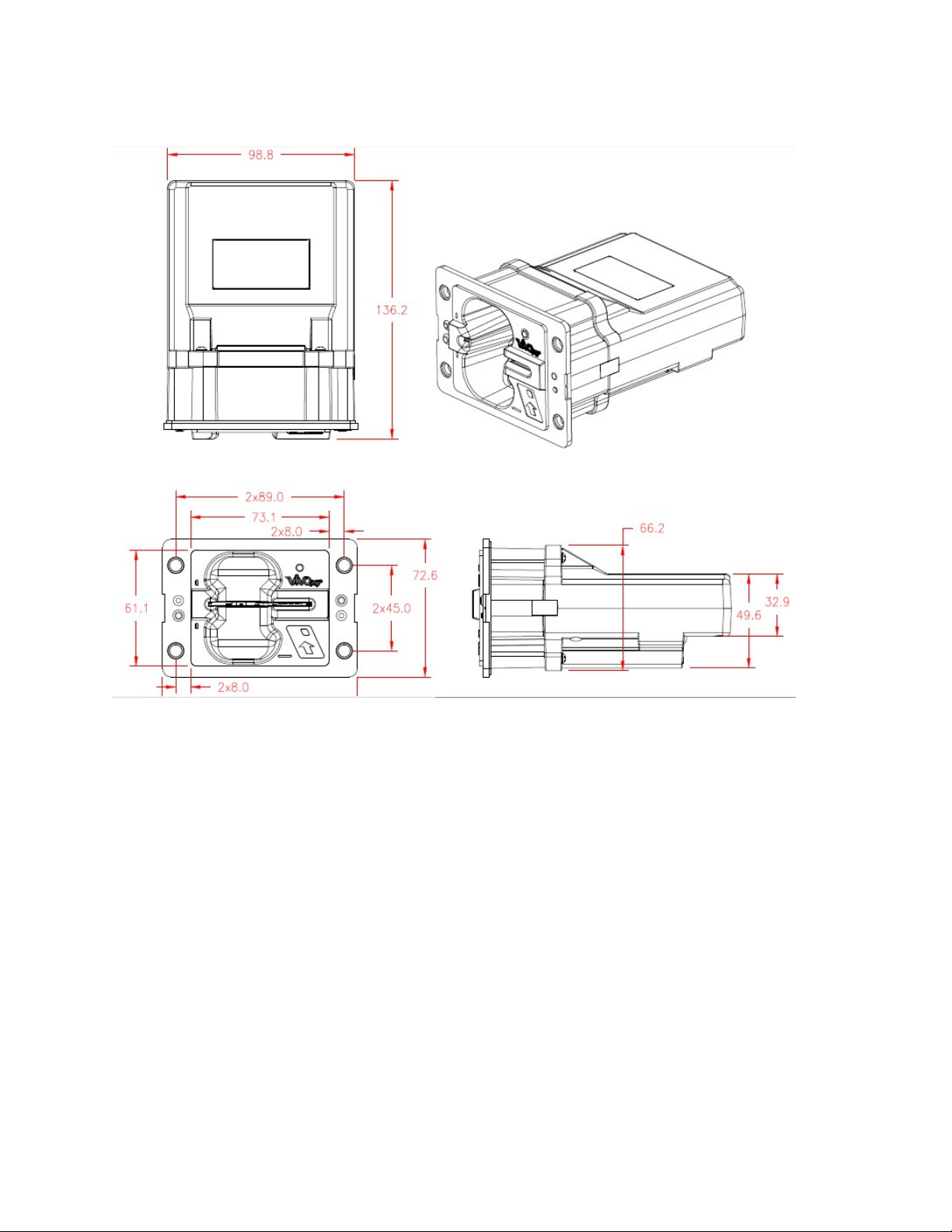
VP5300 Dimensions
136.2 mm from back of mounting surface x 102.8 mm flange
width x 72.6 mm flange height (LxWxH)
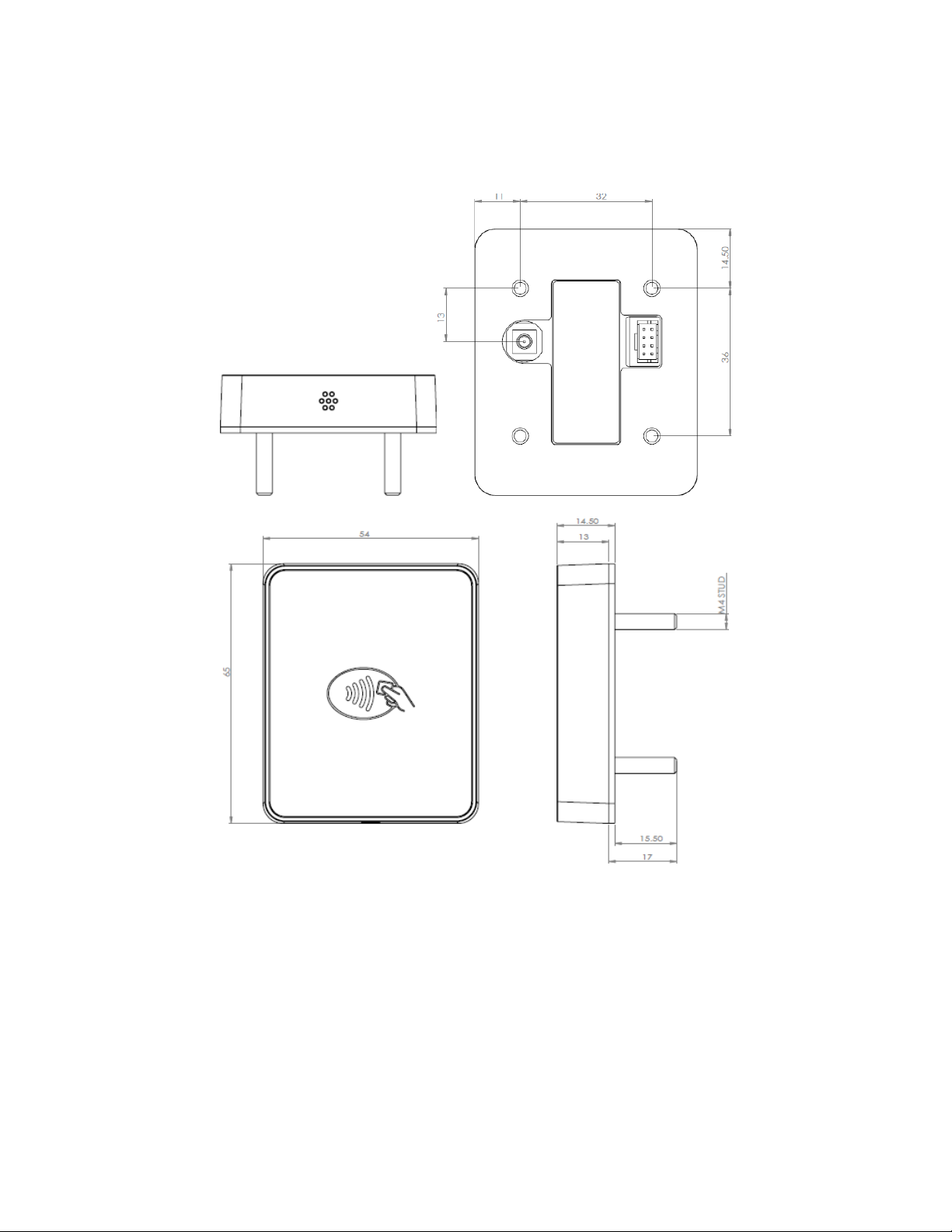
NFC Antenna Bezel Dimensions
65mm x 54mm x 14.5mm (LxWxH), plus 15.5mm-deep M4
studs protruding from the back of the unit
Structure Material
Plastic, PC UL 94V-0
Housing Color
Black
Weight
0.7 kg
Bezel
Metallic, stainless steel look
Water drain feature allows liquids to drain
Cable management
Cables and connectors should be recessed from the case’s
rear surface and facing backwards
Electrical
Voltage Requirement
12V DC (minimum) recommended to 24V maximum
Environmental
Operating Temperature
-25° C to 65° C (-13° F to 158° F), max change of 10° C per
hour
Storage Temperature
-40° C to 80° C (-40° F to 185° F)
Operating Humidity
10% to 95% non-condensing
Storage Humidity
10% to 95% non-condensing, duration 3 months
Transit Humidity
5% to 95% non-condensing, duration 1 week
Operating Environment
Water resistant for indoor and outdoor use
IK Rating
IK 10
IP Rating
IP 65
ESD
1
(Device)
Contact ±6kV
Air discharge ±12kV
ESD (Mag head only)
Contact ±6kV
Air discharge ±12kV
Durability and Reliability
Magnetic Head
1,000,000 swipes minimum
Rail
1,000,000 swipes minimum
Smartcard connector
1,000,000 cycles minimum
Impact Resistance
Pass IK 10 testing
Ingress Resistance
Pass IP 65 rating
NFC Antenna Hardware Specifications
MTBF
466,000 hours
Receiver Subcarrier Data
ISO 14443-2 Type A: Modified Manchester ISO 14443-2 Type
1Note: Cables and connectors must be fully isolated with insulating material to prevent ESD discharge.

VP5300 User Manual
Page | 10
B: NRZ-L, BPSK
ISO 18092
ISO 21481 (PCD & NFC)
Typical Read Range
4-6 cm (1.5 to 2.3 inches)
NFC Antenna Electrical Specifications
Reader Input Voltage
Supplied by the VP5300 <500mA (@9VDCIN)
Working Current Rated power
<3.8W
Maximum field strength
2.6 dBuA/m at 3 m

VP5300 User Manual
Page | 11
3. VP5300 Electrical Requirements
Voltage requirement: 9VDC (minimum) is recommended, to 12V maximum.
3.1. Power Consumption
•Stop Mode (without NFC) ≦85uA
•Stop Mode (with NFC) ≦ 85uA
3.2. Current Draw
VP5300 OPERATING MODE:
12VDC
9VDC
Normal
83mA
115mA
Normal+MSR
86mA
120mA
Normal+ContactLess
190mA
264mA
Normal+Contact EMV
85mA
125mA
Normal+Lan Connection
120mA
165mA
Normal+L100
150mA
200mA
Normal+Contactless+L100
245mA
357mA
Normal+Contactless+L100+ Lan
connection
285mA
410mA
Normal+Contactless+L100+Lan
connection
+BuzzerX2
325mA
470mA
Normal+L80
123mA
156mA
Normal+Contactless+L80
231mA
305mA
Normal+Contactless+L80+ Lan
connection
254mA
334mA
Normal+Contactless+L80+Lan
connection
+BuzzerX2
275mA
352mA
Sleep Mode, NFC off
Sleep Mode, NFC on
47 μA
490 μA
88 μA
500 μA
Stop Mode, NFC off
42 μA
83 μA
Stop Mode, NFC on
560 μA
490 μA
Battery: The unit contains a small lithium battery to power the Real Time Clock and certain anti-
tamper features. This battery has a shelf life of five years. The battery is not user-replaceable. Do not
attempt to open the VP5300 for any reason; this will trigger the anti-tamper features, causing the
unit to become inoperable. If battery replacement is required, return the VP5300 to ID TECH. Contact
support@idtechproducts.com for more information.

VP5300 User Manual
Page | 12
3.3. Low-Power Modes
The VP5300 has two low-power modes: Sleep Mode and Stop Mode. Power management is at the
discretion of the application developer and set with firmware command F0-03 (which is described in
the NEO Interface Developers Guide, available on request). Note that using the F0-03 command to
control the unit's power state is limited to RS-232 operation and is not available in USB mode. Also
note that when the VP5300 has been put in Stop Mode with the F0- 03 command, waking up the unit
causes a warm reboot, which can take 5 seconds or more. Waking the unit up from Sleep Mode does
not cause a reboot.
The VP5300 can be awakened in RS-232 mode from Sleep Mode or Stop Mode by sending the device
any command. In USB mode, establishing the USB connection wakes up the device.
VP5300 User Manual
Page | 13
4. VP5300 3-View Drawing
VP5300 User Manual
Page | 14
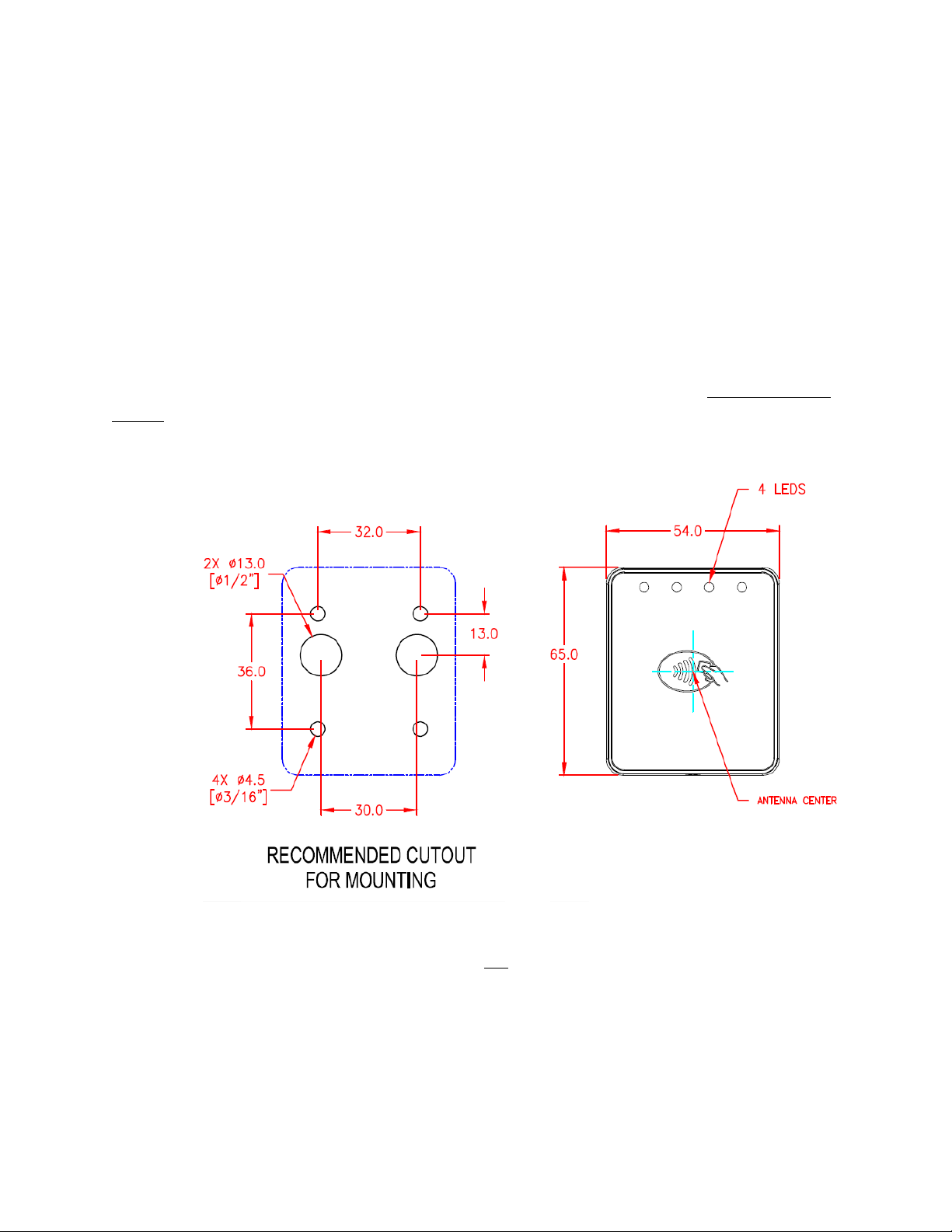
5. NFC Antenna 3-View
Antenna mounting details:

VP5300 User Manual
Page | 15
6. VP5300 Installation
This section provides information on how to install the VP5300 in an enclosure.
Note that the unit may be installed edgewise (vertically), or in a horizontal manner. It can also be
bolted to a surface, or custom-mounted flush with a surface. In the latter case, be sure to allow a
3mm (minimum) cutout clearance around the edge of the metal face flange (assuming the enclosure
is metallic), to maintain good NFC performance. Do not tightly flush-mount the unit to a metal
enclosure. Test NFC performance thoroughly to be sure no interference or signal attenuation occurs.
6.1. Parts List
Make sure you have the following items before you start evaluation and testing:
•VP5300 Demo unit
•L100 or L80 Demo unit
•NFC Antenna
•USB Cable
•RS232 Cable
•VP5300-L100 or -L80 cable
•Power plug with EUR, AUS, UK
•Mounting Brackets (801592239-001) x3 - 1 for the VP5300, 2 for the L100 or L80
6.2. Installing the Reader
Refer to the VP5300 3-view drawing. Verify that power cords can physically reach the unit. Then
proceed to:
•Locate, mark, and drill holes for the four main mounting points of the unit, spaced 89 mm
apart lengthwise (on center), and spaced 45 mm apart (on center) along the short axis. Use a
#12 drill.
•Secure the unit to the enclosure with bolts or screws of appropriate depth. Note that the anti-
tamper nubs, located behind the mounting gasket on the unit's right side (when viewed head-
on; the side nearest the molded-in ViVOpay logo), must be depressed when the unit is
mounted. Ensure that the gasket is compressed to a degree necessary to ensure anti-tamper
nub depression (and to protect against unnecessary moisture ingress).
VP5300 User Manual
Page | 16
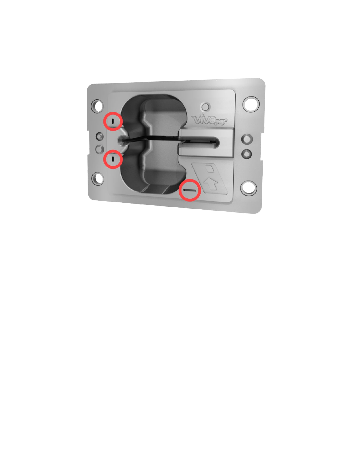
6.2.1. Reader Drainage Holes
VP5300 readers have three drainage holes, shown below. When mounting, make sure to keep the
drainage holes exposed to allow liquid to drain from the reader.
VP5300 User Manual
Page | 17
6.3. Mounting the VP5300 External NFC Antenna
Refer to the VP5300 Antenna 3-view drawing. If you are using the VP5300’s contactless capability,
you will need to install the optional NFC antenna and its cabling.
Use the following instructions to mount the antenna on the exterior of a kiosk.
Note: Product installers should experiment with and verify the orientation of the NFC Antenna before
marking and drilling mounting holes, ensuring that the antenna is far enough away from the main
body of the VP5300 so that insertion of a "tap card" in the unit's contact-EMV slot does not trigger an
unwanted NFC interaction.
Important: Mark holes in such a way as to ensure that the NFC Antenna is oriented with the LEDs at
the top.
1. Locate and mark the four 4.5 mm (3/16 inch) mounting holes.
2. Locate and mark two 14.0 mm (0.551 inches) access holes (used for connecting the
antenna barrel connector and the LED power and data cable to the unit. Notice that these
holes are located off-center toward the top of the unit.
3. Drill the four 4.5 mm (3/16 inch) mounting holes.

VP5300 User Manual
Page | 18
4. Drill the two access holes (14.0 mm, 0.551 inch) holes using a 35/64 drill bit.
5. Use the nuts that are supplied with the unit (in plastic bag).
6. Route the end of the cable (80152235-001) with the RJ-45 connector through the
matching 14.0 mm (0.551 inch) hole into the kiosk. Make sure that the front of the
antenna will be properly oriented (not upside down) on the kiosk before inserting the four
screws into the mounting holes.
7. Align the four threaded posts with their mounting holes and attach the NFC Antenna to
the mounting surface. Make sure that the cable is not pinched, rubbing, or binding.
VP5300 User Manual
Page | 19
8. Use the four nuts to secure the NFC Antenna to the surface of the kiosk. Make sure to
tighten the nuts securely so that the antenna does not move freely on the outside
surface of the kiosk.
Note: Tighten the nuts to 5-7 in/lbs. for a good weather-tight seal.
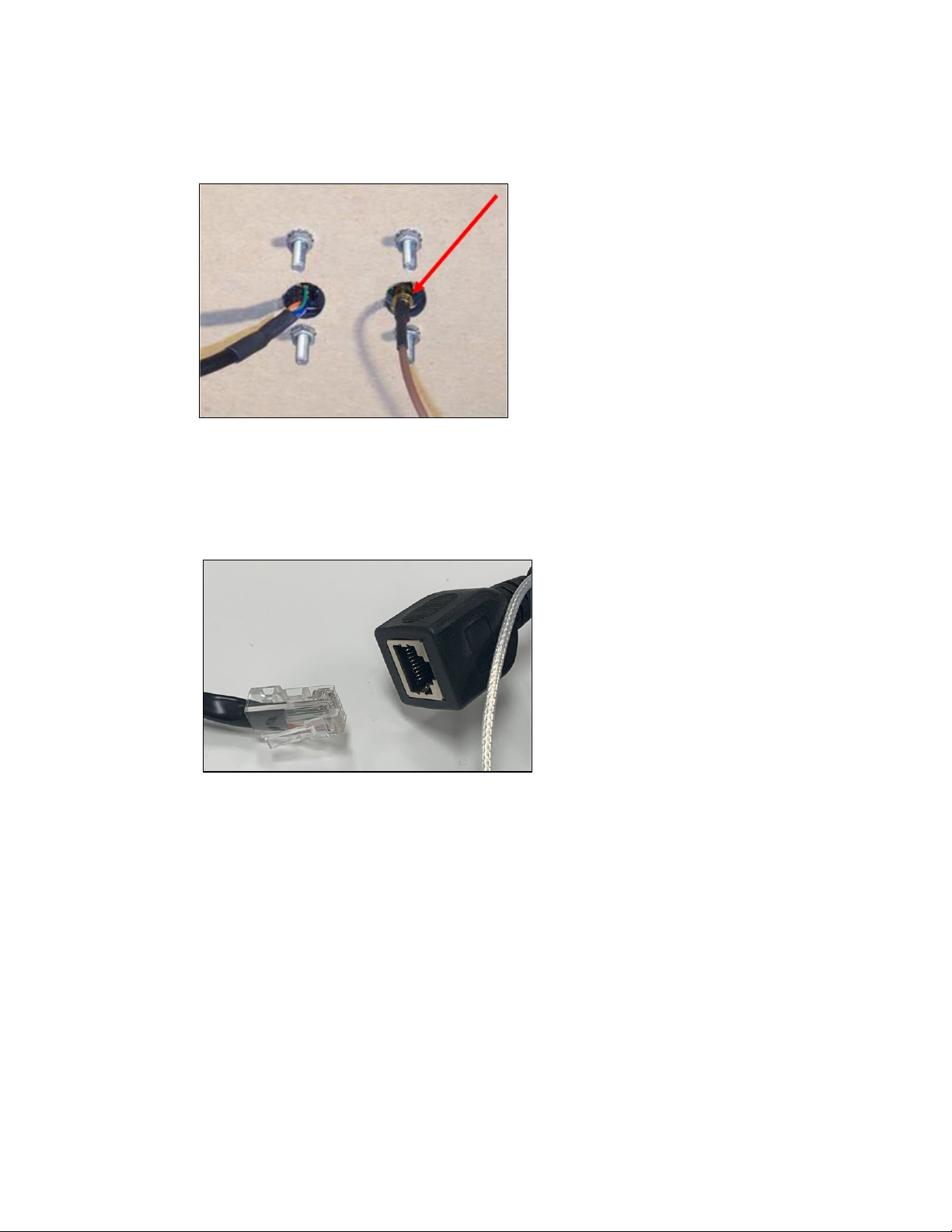
9. Attach the end of the cable with the SMB barrel connector through the right 14.0 mm
(0.551 inch) hole and secure it to its socket on the back of the antenna. The SMB
connector pushes onto the socket.
10. Attach the RJ-45 connector (male) coming from the NFC Antenna to the RJ-45 receptacle
(female) on the 80152236-001 cable
.

VP5300 User Manual
Page | 20
6.3.1. Recommended Mounting Locations
Note: The 10mm gap described in the above diagram can be either an air gap or flush plastic
material; the restriction is that metal needs to be more than 10mm away from the antenna.
6.3.2. Flush-Mounting the Antenna
The antenna’s RF field is sensitive to the proximity of metal. There are three options when flush-
mounting the antenna in a metal surface or bezel:
1. Mount with the RF emitting surface of the antenna at least 1cm forward of anymetal.
2. Mount with the RF emitting surface of the antenna at least 1cm behind any metal.
Note: this reduces the antenna’s effective range.
3. Mount flush with the metal but allow a minimum of 1cm spacing between the antenna and
the metal.
In all three cases, make sure to test the antenna mounting before engaging in a production-ready
installation.
This manual suits for next models
1
Table of contents
Other IDTECH Credit Card Machine manuals

