Ikco SAMAND User manual

SAMAND
(XU7JPL3)
Service Manual
Heating & Ventilation

Chapter:
Section:
Product:
SAMAND XU7JPL3
Heating and Ventilation
I
SAMAND
Service Manual
Foreword:
This Service Manual contains descriptions of the following categories for the
Samand:
Heating and Ventilation
This manual should be used as service manual and s workbook for
training instructors and technicians. We reserve the right to introduce
change without prior notice.

Contents
Heating and ventilation
.......................................... 5
Special tools
Special tools ............................................................ 6
Technical data
Compressor ............................................................. 9
Expansion valve ......................................................... 9
R134a refrigerant ......................................................... 9
Temperature sensor ....................................................... 10
Pressostat .............................................................. 10
Torque settings .......................................................... 11
Technical description
System overview ......................................................... 13
Function of AC system ..................................................... 14
Adjustment and replacement
Refrigerant circuit-draining, vacuum extraction and refilling .......................... 16
Compressor ............................................................. 18
Compressor drive plate .................................................... 20
Compressor drive pulley ................................................... 21
Compressor oil level ...................................................... 22
Compressor air gap ....................................................... 23
Condenser .............................................................. 24
Dehydration reservoir ...................................................... 25
Evaporator .............................................................. 26
Expansion chamber ....................................................... 29
Heater blower ........................................................... 31
Blower module ........................................................... 32
Interior air temperature sensor ............................................... 33
Air conditioning control unit ................................................. 34
Air conditioning control card ................................................. 35
Heater matrix ............................................................ 36
Heater ................................................................. 37
Coolant temperature unit ................................................... 39
Electronic thermostat ...................................................... 40
Scuttle air intake filter ..................................................... 41
Evaporator sensor ........................................................ 42
Air conditioning compressor relay ............................................ 43
Blower relay ............................................................ 44
Heating and Ventilation
5
Special tools
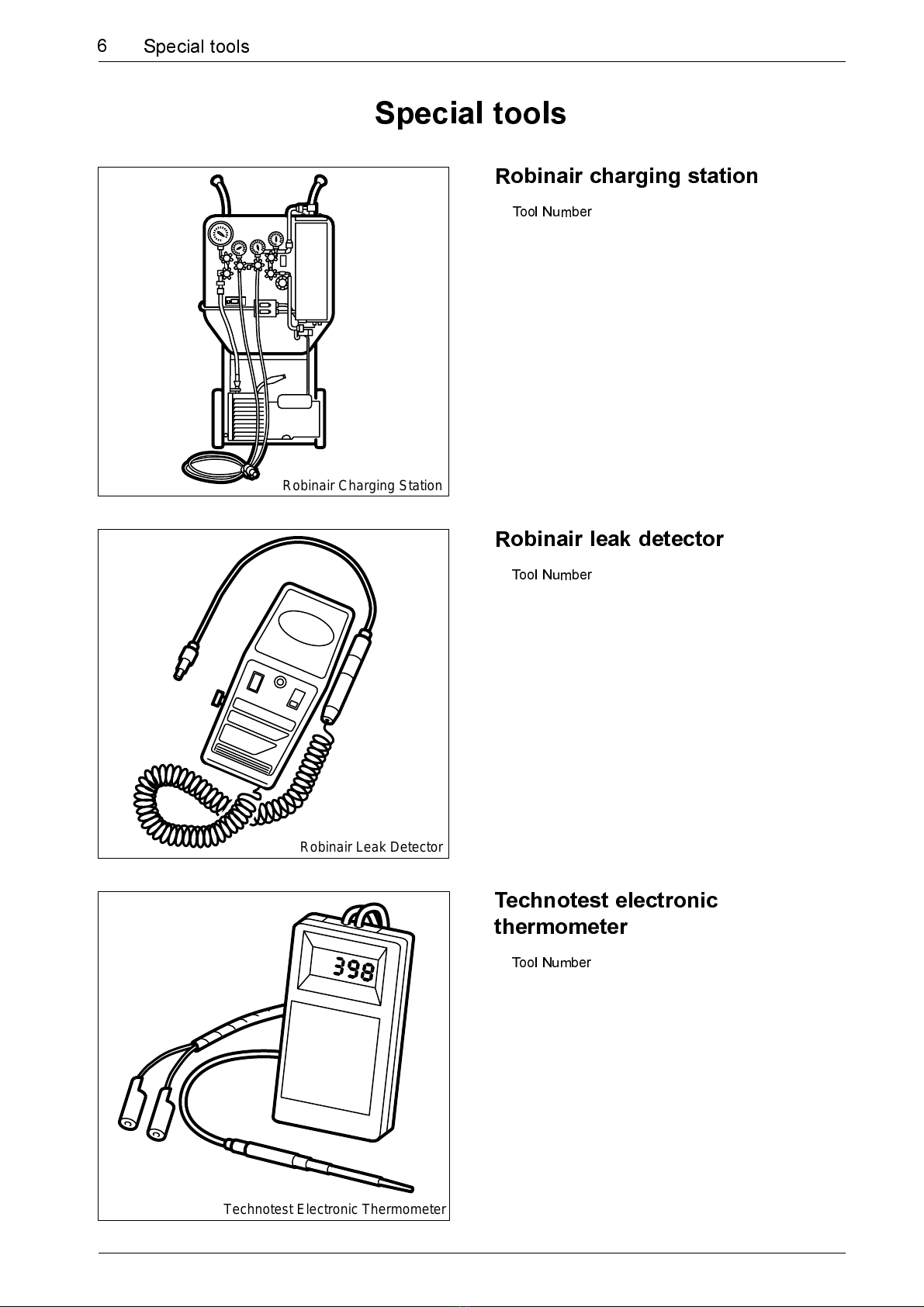
Robinair charging station
Tool Number
Robinair leak detector
Tool Number
Technotest electronic
thermometer
Tool Number
Robinair Charging Station
Robinair Leak Detector
Technotest Electronic Thermometer
6Special tools

Three legged puller
Tool Number
Adjustable peg spanner
Tool number
Compressor dip stick
Tool number
Three Legged Extractor
Adj Peg Spanner
Dipstick
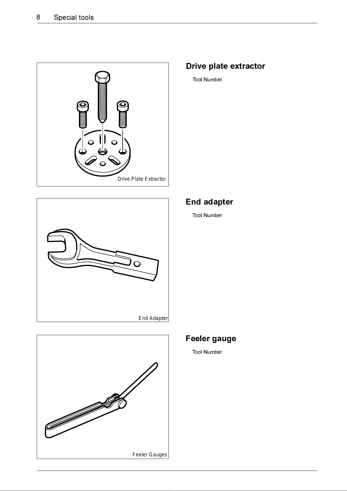
Drive plate extractor
Tool Number
End adapter
Tool Number
Feeler gauge
Tool Number
Drive Plate Extractor
End Adapter
Feeler Gauges
8Special tools

9
Technical data
Peykan
Technical data
Compressor
Type SD7H15
Cylinder volume 154,9cc
Oil capacity 135cc
Clutch type PV
Speed 8000 RPM Max
Wieght 7.2kg
Oil type SP10 OR SP20
Expansion Valve Egelhof
Type
Capacity
Static overheating
R134a
Capacity 600gr+0-50
W710D003
W710D006

W710D005
10 Technical data
Temperature sensor
Reference required
Pressostat
Data 2.5 +-0.5 bar on
Data 17 +-1 bar on
26 +-1.5 off
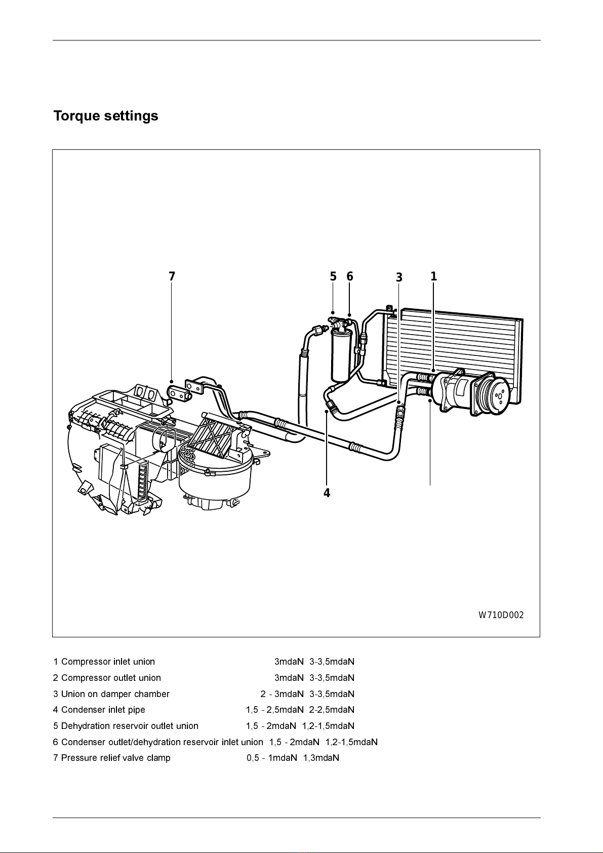
Torque settings
W710D002
61
53
7
42
1 Compressor inlet union 3mdaN 3-3,5mdaN
2 Compressor outlet union 3mdaN 3-3,5mdaN
3 Union on damper chamber 2 - 3mdaN 3-3,5mdaN
4 Condenser inlet pipe 1,5 - 2,5mdaN 2-2,5mdaN
5 Dehydration reservoir outlet union 1,5 - 2mdaN 1,2-1,5mdaN
6 Condenser outlet/dehydration reservoir inlet union 1,5 - 2mdaN 1,2-1,5mdaN
7 Pressure relief valve clamp 0,5 - 1mdaN 1,3mdaN

13
Technical description
Peykan
Technical description
System overview
W710D001
1234
8765
Heating and ventilation
1 Pressure relief valve
2 Dehydration reservoir
3 Condenser
4 Compressor
5 Blower
6 Evaporator
7 Electronic thermostat
8 Heater matrix
W710D003
W710D004
W710D005
14 Technical description
Function of AC system
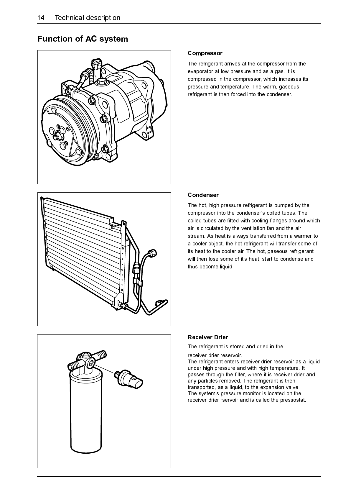
Compressor
The refrigerant arrives at the compressor from the
evaporator at low pressure and as a gas. It is
compressed in the compressor, which increases its
pressure and temperature. The warm, gaseous
refrigerant is then forced into the condenser.
Condenser
The hot, high pressure refrigerant is pumped by the
compressor into the condensers coiled tubes. The
coiled tubes are fitted with cooling flanges around which
air is circulated by the ventilation fan and the air
stream. As heat is always transferred from a warmer to
a cooler object, the hot refrigerant will transfer some of
its heat to the cooler air. The hot, gaseous refrigerant
will then lose some of its heat, start to condense and
thus become liquid.
Receiver Drier
The refrigerant is stored and dried in the
receiver drier reservoir.
The refrigerant enters receiver drier reservoir as a liquid
under high pressure and with high temperature. It
passes through the filter, where it is receiver drier and
any particles removed. The refrigerant is then
transported, as a liquid, to the expansion valve.
The systems pressure monitor is located on the
receiver drier rservoir and is called the pressostat.
15
Technical description
W710D006
W710D007
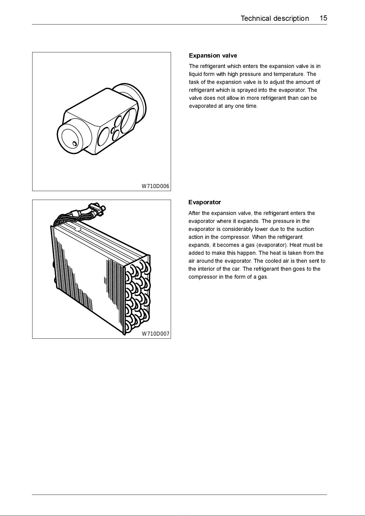
Expansion valve
The refrigerant which enters the expansion valve is in
liquid form with high pressure and temperature. The
task of the expansion valve is to adjust the amount of
refrigerant which is sprayed into the evaporator. The
valve does not allow in more refrigerant than can be
evaporated at any one time.
Evaporator
After the expansion valve, the refrigerant enters the
evaporator where it expands. The pressure in the
evaporator is considerably lower due to the suction
action in the compressor. When the refrigerant
expands, it becomes a gas (evaporator). Heat must be
added to make this happen. The heat is taken from the
air around the evaporator. The cooled air is then sent to
the interior of the car. The refrigerant then goes to the
compressor in the form of a gas.

W710R065
2
1
Draining
1 High pressure valve.
2 Low pressure valve.
Note
The high pressure valve is fitted on the pipe with the
smallest diameter.
Drain the circuit via the low pressure valve (gaseous
zone) very slowly to avoid draining the compressor oil.
Refilling
Imperative
Before filling the circuit with refrigerant, it is necessary
to carry out a vacuum extraction to dry the circuit.
1 Connect the filling equipment to the service
valves.
2 Carry out a vacuum extraction
(draining time 15 minutes)
3 Check the sealing of the circuit:
The vacuum should be held for more than
5 minutes.
4 Carry out a pre-filling:
300g.
5 Check the sealing of the circuit.
6 Drain the refrigerant circuit.
7 Carry out a vacuum extraction
(draining time 30 minutes minimum).
8 Charge the circuit with the specified quantity of
refrigerant.
Adjustments and replacement
Refrigerant circuit - draining, vacuum extraction and refilling
W710R001
4
W710R002
56
7
W710R003
8
8
18 Adjustment and replacement
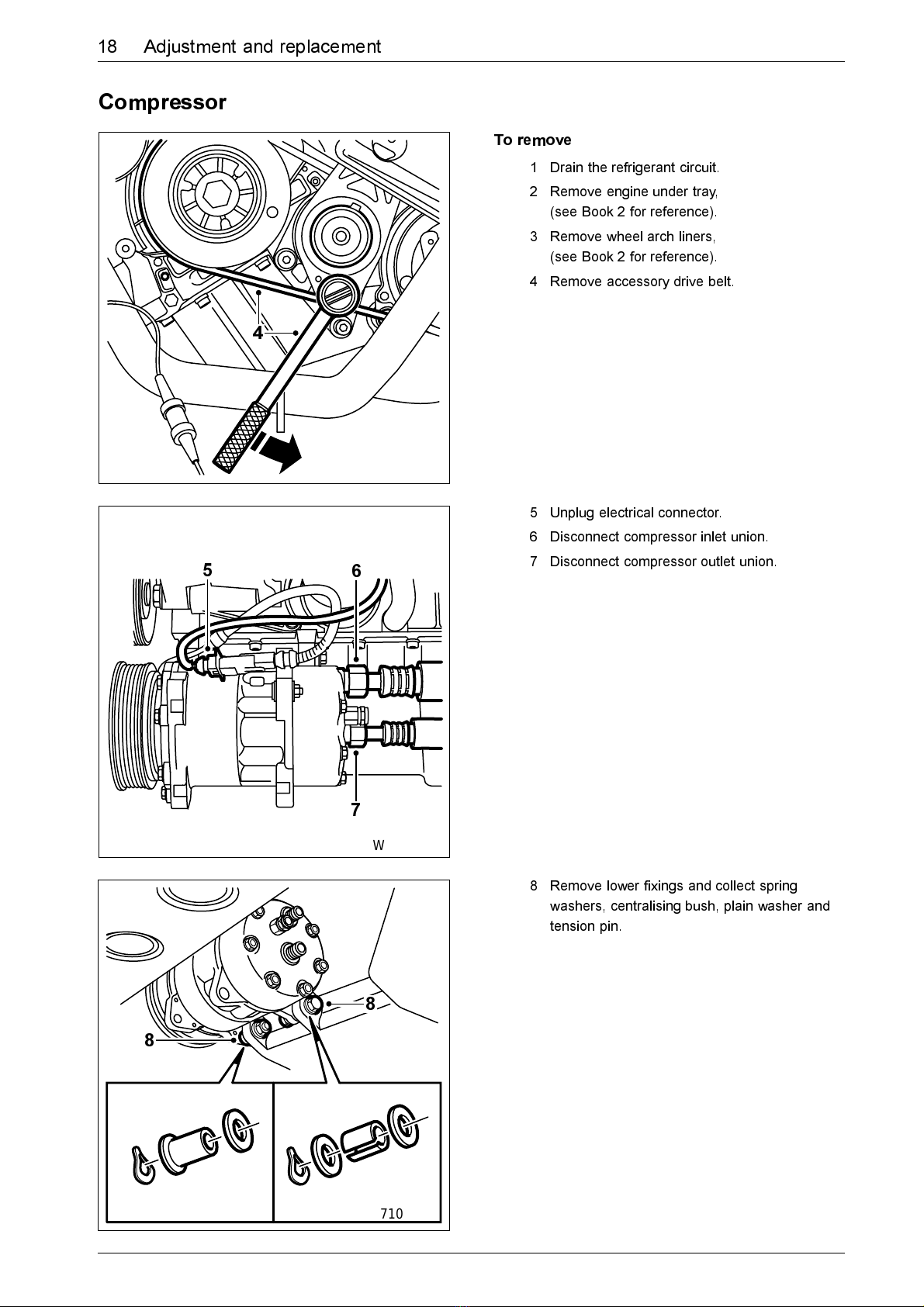
Compressor
To remove
1 Drain the refrigerant circuit.
2 Remove engine under tray,
(see Book 2 for reference).
3 Remove wheel arch liners,
(see Book 2 for reference).
4 Remove accessory drive belt.
5 Unplug electrical connector.
6 Disconnect compressor inlet union.
7 Disconnect compressor outlet union.
8 Remove lower fixings and collect spring
washers, centralising bush, plain washer and
tension pin.

19
Adjustment and replacement
W710R004
99
10
9 Remove upper fixing bolts.
10 Remove compressor.
To fit
Fit in reverse order.
Note
Ensure washers and spacers are correctly fitted.
All fixing bolts have a tightening torque of 5mdaN.

W710R063
3
2
W710R064
4
5
20 Adjustment and replacement
Compressor drive plate
To remove
1 Remove compressor from car.
2 Attach peg spanner.
3 Slacken the central locking nut and remove.
4 Fit the extractor special tool.
5 Extract the drive plate.
To fit
Fit in reverse order.
Note
Fit the old nut and tighten to 3,5-4 mdaN.
Check and adjust the air gap if required.
Fit a new nut in place of the old one and
tighten to 3,5-4 mdaN.

21
Adjustment and replacement
W710R061
3
2
W710R062
4
4
Compressor drive pulley
To remove
1 Remove compressor from car.
2 Remove the drive plate.
3 Remove circlip, washers and key.
4 Fit the extractor special tool and remove
pulley.
To fit
Fit in reverse order.
Note
Fit the old nut and tighten to 3,5-4 mdaN.
Check and adjust the air gap if required.
Fit a new nut in place of the old one and
tighten to 3,5-4 mdaN.

W710R059
1
2
W710R060
3
22 Adjustment and replacement
Compressor oil level
To check
1 Remove plug.
2 Turn compressor pulley by hand to reveal:
a. The inclination of the control plate.
b. The connecting rod, while looking through
the oil filler hole.
3 Position the chamfered face of the dip stick
against the body of the compressor.
Note
The dipstick must enter the compressor without
excessive constraint.
The value should be 6 graduations on the dipstick.
If required, adjust oil level to specified value.
4 Replace plug.

23
Adjustment and replacement
W710R005
W710R006
23
44
W710R007
2,4
Compressor air gap
To measure
1 Measure the air gap between the drive plate
and the pulley.
Measure in at least 3 places.
The air gap should be 0,4 - 0,8mm.
Adjustment
2 If the air gap is incorrect, remove drive plate
retaining nut.
3 Release drive plate and collect washers and
key.
4 Adjust the air gap by changing:
a. Thickness of the washers.
b. The number of washers.
To fit
1 Refit the drive plate.
2 Fit the old nut and tighten to 3,5-4 mdaN.
3 Check and adjust the air gap if required.
4 Fit a new nut in place of the old one and
tighten to 3,5-4 mdaN.
Other manuals for SAMAND
2
Table of contents
Other Ikco Automobile manuals


