imes-icore iVAC eco+ Quick start guide

1 Version 1 Aug 2012
iVAC eco+
DUST EXTRACTION UNIT
OPERATIONAL INSTRUCTIONS

2 Version 1 Aug 2012
TABLE OF CONTENTS
SAFETY INSTRUCTIONS.....................................................................................................3
Symbols used ................................................................................................................ 3
Electrical safety............................................................................................................. 3
Dangers to eyes, breathing and skin ............................................................................ 3
Warning and Information Labels.................................................................................. 4
INSTALLATION .................................................................................................................5
Extractor Overview ....................................................................................................... 5
Extractor Installation Procedure................................................................................... 6
Feature Considerations................................................................................................. 6
Filter blocked signal......................................................................................... 7
Remote stop/start ........................................................................................... 7
Electrical supply connection ......................................................................................... 7
General Safety Requirements ....................................................................................... 8
OPERATION .....................................................................................................................9
Manual operation......................................................................................................... 9
MAINTENANCE .............................................................................................................. 10
Maintenance General................................................................................................. 10
Cleaning Unit .............................................................................................................. 10
Replacing Filters ......................................................................................................... 10
Pre filter replacement.................................................................................... 11
Consumable Spares .................................................................................................... 11
Maintenance Protocol ................................................................................................ 12
Filter Disposal ............................................................................................................. 12
TROUBLE SHOOTING...................................................................................................... 13
SYSTEM SPECIFICATIONS................................................................................................ 14
Unit: iVAC eco+ ........................................................................................................... 14
3 Version 1 Aug 2012
SAFETY INSTRUCTIONS
Symbols used
Danger 'Risk of Electric Shock' Refers to an immediately impending danger. If
the danger is not avoided, it could result in death or severe (crippling)
injury. Please consult the manual where this symbol is displayed.
Warning Refers to a possibly dangerous situation. If it is not avoided, it could
result in death or severe injury. Please consult the manual where this
symbol is displayed.
Caution Refers to a possibly harmful situation. If it is not avoided, damage
could be caused to the product or to something in its environment.
Important Refers to handling tips and other particularly useful information.
This does not signify a dangerous or harmful situation.
Electrical safety
This extraction unit is designed to meet the safety requirements of the Low Voltage
Directive 2006/95/EC(previously numbered 73/23/EEC).
Warning During works with the pump/motor housing open, live, 230/115 volt
components are accessible. Make sure that rules and regulations
for work on live components are always observed.
Important To reduce the risk of fire, electric shock or injury:
1. Always isolate the system from the mains power supply before
removing the pump/motor panel.
2. Use only as described in the manual.
3. Connect to a properly grounded outlet.
Dangers to eyes, breathing and skin
Once used, the filters in the extraction unit may contain a mixture of particulates,
some of which may be sub micron size. When the used filters are moved it may
agitate some of this particulate, which could get into the breathing zone and eyes of
the operative. Additionally, depending on the materials being used, the particulate
may be an irritant to the skin.
Caution: When changing used filters always wear mask, safety glasses and gloves.
4 Version 1 Aug 2012
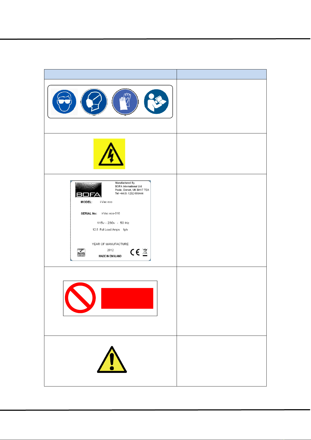
Warning and Information Labels
Label/Symbol
Position
Inside Filter Door (at top)
Top Left of rear panel
Rear of unit, next to power
connection
DO NOT COVER
Above motor cooling on rear of
unit
Top Left of Front Door

5 Version 1 Aug 2012
INSTALLATION
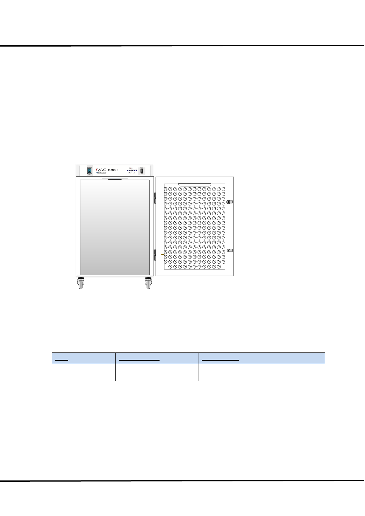
Extractor Overview
This unit provides extraction and filtration of the fume generated by marking, milling,
cutting, etching or engraving. The units are of robust design and feature ease of use
with minimal maintenance. The main components are shown in Fig. 1.
Fig. 1
1. Unit/Filter Condition Display
2. On/Off Switch
3. Motor function switch
4. Hose Inlet Connection 50mm
5. Signal/Interface Connection
6. Power inlet
7. Cooling air inlet
8. Exhaust/Cooling air outlet
9. Filter door catch
Bag Filter
1
23
4
56
78
9

6 Version 1 Aug 2012
Extractor Installation Procedure
Caution
If this equipment is used in a manner not specified by the manufacturer, the
protection provided by the equipment may be impaired.
Read all instructions in this manual before using this extractor.
1. Move the unit to the location where it is going to be installed and remove the unit
from its packaging. The unit should be installed in a well ventilated room.
Caution
Due to the weight involved the extractor unit should only be lifted using suitable lifting
equipment and with regard to appropriate safety precautions. (See Appendix for
product weight details).
2. Ensure that a 0.5m space is available around any louvered areas of the unit to
ensure adequate air flow. Lock the two braked castors, if fitted.
Caution
Do not block or cover any louvers or cooling holes on the unit as this severely
restricts air flow and may cause damage to the unit.
Caution
Under no circumstances should the exhaust outlet/s be covered as this will restrict
the airflow and cause overheating.
3. Check filters are located in their correct position and carefully replace lid/close
door.
4. Connect the extraction ducting between the extractor inlet and the fume capture
device.
Feature Considerations
5. The following features need to be considered when installing the unit:

7 Version 1 Aug 2012
Filter blocked signal
With this, the extraction unit has been fitted with a pressure switch to monitor the
condition of the filters. This is displayed via the Red LED on the front of the unit. This
circuit will not directly stop the extractor motor.
Remote stop/start
This enables the extractor unit to be turned on and off by a signal from the customer.
Pins 3 & 4 of the connector need to be connected to a 24v dc supply to start the unit.
However the mains power switch must be in the “on” position for the signal to be
effective.
Fig 2
Remote operation can be overridden by using the override switch, which is mounted
on the front the unit (see fig. 3).
Fig 3
Manual
Auto
Extraction
Electrical supply connection
6. Check the integrity of the electrical power cable.
Connect the power cable to an isolated electrical supply. The mains socket outlet
should be installed near the equipment and be easily accessible. The cable run to the
machine should be arranged so as not to create a trip hazard.
Pins 3 & 4
Vacuum Motor
Remote

8 Version 1 Aug 2012
Caution:
Check that the mains input at the isolated supply is the same as the voltage Supply
detail on the Serial Number label before plugging the extractor unit in.
General Safety Requirements
Caution
Do not block or cover the cooling vents on the unit, as this severely restricts airflow
and may cause damage to the unit.
Caution
This unit is over 18Kgs in weight and should only be lifted with suitable lifting
equipment.
Caution
If this equipment is used in a manner not specified by the manufacturer, the
protection provided by the equipment may be impaired.
Read all instructions in this manual before using this extractor.
Warning Mains voltage. Dangerous voltages exist in this equipment.
Ensure all covers are fitted before operating this equipment.
The unit is now ready for use.

9 Version 1 Aug 2012
OPERATION
Manual operation
The extraction unit is turned off and on by means of an illuminated rocker switch on
the front of the unit.
Manual
Auto
Extraction
Filter condition signal –indicators & component controls.
The LED on the front panel (see above Fig) indicate when the filter is blocked.
The right switch will allow the vacuum motor to be either On/Off/Auto. Auto will
require a voltage input to the interface connector on the rear of the unit. (see Fig 3)

10 Version 1 Aug 2012
MAINTENANCE
Maintenance General
User maintenance is limited to cleaning the unit and replacing the filters with new.
Only imes-icore trained maintenance technicians are authorised to carry out
component testing and replacement. Unauthorised work or the use of unauthorised
replacement filters may result in a potentially dangerous situation and/or damage to
the extractor unit, and will invalidate the manufacturer’s warranty.
Cleaning Unit
The powder coated finish can be cleaned with a damp cloth and non aggressive
detergent. Do not use an abrasive cleaning product as this will damage the finish.
The cooling inlets and outlets should be cleaned once a year to prevent build up of
dust and overheating of unit.
Replacing Filters
The filter package needs attention when the filter change LED is illuminated or, when
the unit no longer removes the fume efficiently.
A log of filter changes should be maintained by the user.
All filters are tested to BS3928. A certificate on conformity for each filter is available
on request.
It is recommended that a spare set of filters are kept on site to avoid prolonged unit
unavailability. Part numbers for replacement filters can be found on the filters fitted in
your system. Alternatively, refer to the consumable spares table.
Caution
To prevent overheating, units should not be run with a blocked filter condition, or with
dust obstruction of inlets or outlets.
Caution: When changing used filters always wear mask, safety glasses and gloves.
11 Version 1 Aug 2012
Pre filter replacement
The pre filter needs changing when the filter change is illuminated.
Isolate the electrical supply to the extractor.
1. Undo the filter compartment latches on the front of the unit.
2. Remove the pre filter by lowering the supporting plate and replace with a new pre
filter.
3. Push the supporting plate back up so it clips in place, close and fasten filter
compartment latches.
4. Reconnect the electrical supply.
Bag Filter
Consumable Spares
Unit
Part Number
Description
iVAC eco+
513002 0050
5 layer bag filter

12 Version 1 Aug 2012
Maintenance Protocol
Filters to be changed in accordance with instructions. Log the date of filters changed
in the table below:
Unit Serial Number
Pre Filter
Date
Name
Filter Disposal
Pre filters are manufactured from non-toxic materials.
Filters are not re-usable, cleaning used filters is not recommended.
Disposal of the used filters depends on the material deposited on them.
See the following table:
Deposit
EWC listing*
Comment
Non Hazardous
15 02 03
Can be disposed of as non hazardous waste.
Hazardous
15 02 02 M
The type of Hazard needs to be identified and
the associated risks defined. The thresholds for
these risks can then be compared with the
amount of material in the filters to see if they fall
into the hazardous category. If so, the filters will
need to be disposed of inline with the
local/national regulations.
* European Waste Catalogue


14 Version 1 Aug 2012
SYSTEM SPECIFICATIONS
Unit: iVAC eco+
Capacity: 260 m³/hr
Size: Height 750mm x Depth 460mm x Width 440mm
Weight: 30Kg
Exhauster: Centrifugal Blower
Electrical supply: 115-230v 1ph 50/60Hz
FLC: 12.5A
Noise level: Below 75dB (A)
Filters: Pre filter Efficiency F8 95% @ 0.9µ
Environmental Operating Range
Temperature +5°C to +40°C
Humidity Max 80 % RH up to 31°C to Max 50% RH at 40°C
Altitude: Below 2000m
Pollution Degree 2
Table of contents


