IMG STAGE LINE MCL-204 User manual

MCL-204 Best.-Nr. 25.2170
2-KANAL-KOMPRESSOR/LIMITER
2-CHANNEL COMPRESSOR/LIMITER
COMPRESSEUR/LIMITEUR 2 CANAUX
COMPRESSORE/LIMITER A 2 CANALI
BEDIENUNGSANLEITUNG • INSTRUCTION MANUAL • MODE D’EMPLOI • ISTRUZIONI PER L’USO
VEILIGHEIDSVOORSCHRIFTEN • CONSEJOS DE SEGURIDAD • ŚRODKI BEZPIECZEŃSTWA
SIKKERHEDSOPLYSNINGER • SÄKERHETSFÖRESKRIFTER • TURVALLISUUDESTA

2
wwwwww..iimmggssttaaggeelliinnee..ccoomm
Bevor Sie einschalten …
Wir wünsch n Ihn n vi l Spaß mit Ihr m n u n G rät
von „img Stag Lin “. Bitt l s n Si di s B di nungs-
anl itung vor d m B tri b gründlich durch. Nur so l rn n
Si all Funktionsmöglichk it n k nn n, v rm id n
F hlb di nung n und schütz n sich und Ihr G rät vor
v ntu ll n Schäd n durch unsachg mäß n G brauch.
H b n Si di Anl itung für in spät r s Nachl s n auf.
D r d utsch T xt b ginnt auf d r S it 4.
Be ore switching on …
W wish you much pl asur with your n w “img Stag
Lin ” unit. Pl as r ad th s op rating instructions car -
fully prior to op rating th unit. Thus, you will g t to know
all functions of th unit, op rating rrors will b pr -
v nt d, and yours lf and th unit will b prot ct d
against any damag caus d by improp r us . Pl as
k p th op r ating instructions for lat r us .
Th English t xt starts on pag 4.
Avant toute installation …
Nous vous souhaitons b aucoup d plaisir à utilis r c t
appar il “img Stag Lin ”. Lis z c mod dʼ mploi ntiè-
r m nt avant tout utilisation. Uniqu m nt ainsi, vous
pourr z appr ndr lʼ ns mbl d s possibilités d fonc-
tionn m nt d lʼappar il, évit r tout manipulation rroné
t vous protég r, ainsi qu lʼappar il, d dommag s év n-
tu ls ng ndrés par un utilisation inadapté . Cons r-
v z la notic pour pouvoir vous y r port r ultéri ur m nt.
La v rsion français s trouv pag 14.
Prima di accendere …
Vi auguriamo buon div rtim nto con il vostro nuovo
appar cchio di “img Stag Lin ”. L gg t att ntam nt
l istruzioni prima di m tt r in funzion lʼappar cchio.
Solo così pot t conosc r tutt l funzionalità, vitar
comandi sbagliati prot gg r voi st ssi lʼappar cchio
da v ntuali danni in s guito ad un uso improprio. Con-
s rvat l istruzioni p r pot rl consultar anch in
futuro.
Il t sto italiano inizia a pagina 14.
D
A
CH
GB
Antes de la utilización …
L d s amos una bu na utilización para su nu vo apa-
rato “img Stag Lin ”. Por favor, l a los cons jos d
s guridad d talladam nt ant s d hac r funcionar l
aparato para prot j rs y prot j r la unidad d cualqui r
daño causado por una mala utilización, guard las
instruccion s para una utilización post rior.
Los cons jos d s guridad pu d n ncontrars n la
página 24.
Voor u inschakelt …
Wij w ns n u v l pl zi r m t uw ni uw apparaat van
“img Stag Lin ”. L s d v iligh idsvoorschrift n gron-
dig door, alvor ns h t apparaat in g bruik t n m n. Zo
b ho dt u zichz lf n h t apparaat voor v ntu l
schad door ond skundig g bruik. B waar d handl i-
ding voor lat r raadpl ging.
D v iligh idsvoorschrift n vindt u op pagina 24.
Przed uruchomieniem …
Życzymy zadowol nia z now go produktu “img Stag
Lin ”. Prosimy zapoznać się z informacjami dotyczącymi
b zpi cz ństwa prz d użytkowani m urządz nia, w t n
sposób zdrowi użytkownika ni będzi zagrożon , a
urządz ni ni ul gni uszkodz niu. Instrukcję nal ży
zachować do wglądu.
Informacj dotycząc b zpi cz ństwa znajdują się na
stroni 24.
Før du tænder …
Vi håb r, du bliv r glad for dit ny “img Stag Lin ” pro-
dukt. Læs sikk rh dsanvisning rn nøj før ibrugtag-
ning, for at b skytt D m og nh d n mod skad r, d r
skyld s fork rt brug. G m manual n til s n r brug.
Sikk rh dsanvisning rn find s på sid 25.
Innan du slår på enheten …
Vi önskar dig myck t glädj m d din nya “img Stag Lin ”
produkt. Läs ig nom säk rh tsför skrift rna innan n h -
t n tas i bruk för att undvika skador till följd av f laktig
hant ring. B håll instruktion rna för framtida bruk.
Säk rh tsför skrift rna åt rfinns på sidan 25.
Ennen kytkemistä …
Toivomm Sinull paljon mi llyttäviä h tkiä uud n “img
Stag Lin ” laitt n kanssa. Enn n laitt n käyttöä Sinua
huol llis sti tutustumaan turvallisuusohj isiin. Näin vältyt
vahingoilta, joita virh llin n laitt n käyttö saattaa
aih uttaa. Ol hyvä ja säilytä käyttöohj t myöh mpää
tarv tta vart n.
Turvallisuusohj t löytyvät sivulta 25.
F
B
CH
I
ENL
PL DK
SFIN
B

3
12 13 14 15 16 17 18 19 20 21 22 23 24 25
45678 910 11
26 27 28 29 30 31 32 33 34 28 29 30 31 32 33 34
123

Contents
1 Operating Elements and Connections ...4
1.1 Frontpanel ..........................4
1.2 Operating panel of channel A . . . . . . . . . . . . 4
1.3 Rearpanel ..........................5
2 Safety otes ........................5
3 Applications ........................6
4 Setting Up ..........................6
5 Connecting the Unit ..................6
5.1 Inserting the compressor into
thechannelofamixer .................6
5.2 Inserting the compressor between
twoaudiounits .......................7
5.3 Using the sidechain connections . . . . . . . . . 7
5.4 Powersupply ........................7
6 Operation ...........................7
6.1 Adjusting the correct operating level . . . . . . 7
6.2 Adjusting the expander/gate . . . . . . . . . . . . . 7
6.3 Adjusting the compressor . . . . . . . . . . . . . . . 8
6.3.1 Threshold and ratio . . . . . . . . . . . . . . . . . . 8
6.3.2 Outputlevel ........................9
6.3.3 Soft/hardknee......................9
6.3.4 Attack and release times, AUTO button . . 9
6.4 Adjusting the limiter . . . . . . . . . . . . . . . . . . 10
6.5 SI ECHAIN FILTER . . . . . . . . . . . . . . . . . . 10
6.6 Sidechain applications . . . . . . . . . . . . . . . . 10
6.6.1 Frequency-dependent dynamics
de-esser, expander/gate . . . . . . . . . . . . . 10
6.6.2 Externally controlled dynamics
ducker, expander/gate . . . . . . . . . . . . . . 11
7 Specifications ......................12
Please unfold page 3. Then you will always see the
operating elements and connections described.
1 Operating Elements and
Connections
1.1 Front panel
1Operating panel for channel A (details see fig. 2)
2Operating panel for channel B, corresponds to
channel A except for the VU-meter (11) which is
situated on the left
3POWER switch with power LE
1.2 Operating panel of channel A
4LE s +/
-
LE “+”: the input signal is above the threshold
adjusted and remains unchanged
LE “
-
”: the input signal is below the threshold
adjusted and will be attenuated by the
expander
5Button SC EXT to switch over the sidechain con-
trol signal
button not pressed:
the input signal will also be used as a control
signal for the dynamics processing
button pressed:
a signal applied to the jack SI ECHAIN
RETURN (34) will be used to control the
dynamics processing
When the jack SI ECHAIN RETURN is not
used, the control signal will always be the input
signal.
6LE s
-
/0/+
LE “+”: the input signal is above the threshold
adjusted and will be modified by the compres-
sor
LE “
-
”: the input signal is below the threshold
adjusted und will not be modified by the com-
pressor
LE “0”: when the button SOFT (7) is pressed,
the input signal will be in the transition area
around the threshold adjusted and will be
modified by the compressor with reduced
compression ratio
7Button SOFT to influence the compressor control
button not pressed:
hard start of compression
button pressed:
soft start of compression (soft knee)
8LE indication of present level reduction (com-
pression)
9LE LIMITER, will light up when the output sig-
nal is limited by the limiter
10 LE VU-meter for the input signal or output sig-
nal of channel A; 0 dB corresponds to the rated
level adjusted with the switch +4 dBu /
-
10 dBV
(30)
11 LE VU-meter for the input signal or output sig-
nal of channel B; 0 dB corresponds to the rated
level adjusted with the switch +4 dBu /
-
10 dBV
(30)
12 Control THRESHOL to adjust the threshold for
the expander: If the input signal exceeds the
threshold, the signal will pass unchanged. If it
falls below the threshold, it will be attenuated with
the RATIO (13) adjusted. In the position OFF, the
signal will remain unchanged.
13 Control RATIO to adjust the expansion ratio; with
a ratio of 4 : 1, for example, a reduction of the
input level by 2 dB below the threshold will result
in a reduction of the output level by 8 dB
14 Button SC MONITOR to check the control signal
acoustically; if the button is pressed, instead of
the processed signal, the sidechain control sig-
nal will be sent to the output (28, 29)
D
A
CH
4
GB
Inhalt
1 Übersicht der Bedienelemente
und Anschlüsse .....................4
1.1 Frontseite ...........................4
1.2 BedienfeldKanalA ....................4
1.3 Rückseite ...........................5
2 Hinweise für den sicheren Gebrauch ....5
3 Einsatzmöglichkeiten .................6
4 Aufstellmöglichkeiten . . . . . . . . . . . . . . . . 6
5 Gerät anschließen ...................6
5.1 Kompressor in einen Mischpult-Kanal
einschleifen..........................6
5.2 Kompressor zwischen zwei Audio-
Geräteschalten ......................7
5.3 Nutzung der Sidechain-Anschlüsse . . . . . . . 7
5.4 Stromversorgung .....................7
6 Bedienung ..........................7
6.1 Einstellung des richtigen Arbeitspegels . . . . 7
6.2 Expander/Gate einstellen . . . . . . . . . . . . . . . 8
6.3 Kompressor einstellen . . . . . . . . . . . . . . . . . 9
6.3.1 Threshold und Ratio . . . . . . . . . . . . . . . . . 9
6.3.2 Ausgangspegel .....................9
6.3.3 Weicher oder harter Einsatzpunkt . . . . . . . 9
6.3.4 Attack- und Release-Zeit, AUTO-Taste . 10
6.4 Limitereinstellen.....................10
6.5 SI ECHAIN FILTER . . . . . . . . . . . . . . . . . . 10
6.6 Sidechain-Anwendungen . . . . . . . . . . . . . . 11
6.6.1 Frequenzabhängige ynamik
e-Esser, Expander/Gate . . . . . . . . . . . . 11
6.6.2 Fremdgesteuerte ynamik
ucker, Expander/Gate . . . . . . . . . . . . . . 11
7 Technische Daten ...................12
Bitte klappen Sie die Seite 3 heraus. Sie sehen
dann immer die beschriebenen Bedienelemente
und Anschlüsse.
1 Übersicht der Bedienelemente
und Anschlüsse
1.1 Frontseite
1Bedienfeld für den Kanal A ( etails siehe Abb. 2)
2Bedienfeld für den Kanal B, entspricht dem
Kanal A, nur die Pegelanzeige (11) befindet sich
links
3Ein-/Ausschalter POWER mit Betriebsanzeige
1.2 Bedienfeld Kanal A
4LE s +/
-
LE „+“: das Eingangssignal liegt über dem ein-
gestellten Schwellwert und bleibt unverändert
LE „
-
“: das Eingangssignal liegt unter dem ein-
gestellten Schwellwert und wird durch den
Expander abgeschwächt
5Taste SC EXT zum Umschalten des Sidechain-
Steuersignals
Taste nicht gedrückt:
das Eingangssignal wird auch als Steuersig-
nal für die ynamikbearbeitung verwendet
Taste gedrückt:
ein an der Buchse SI ECHAIN RETURN (34)
anliegendes Signal wird zur Steuerung für die
ynamikbearbeitung verwendet
Bei nicht belegter Buchse SI ECHAIN RETURN
ist das Steuersignal immer das Eingangssignal.
6LE s
-
/0/+
LE „+“: das Eingangssignal liegt über dem ein-
gestellten Schwellwert und wird durch den
Kompressor verändert
LE „
-
“: das Eingangssignal liegt unter dem ein-
gestellten Schwellwert und wird vom Kom-
pressor nicht verändert
LE „0“: das Eingangssignal liegt, wenn die
Taste SOFT (7) gedrückt ist, im Übergangs-
bereich um den eingestellten Schwellwert und
wird vom Kompressor mit reduziertem Kom-
pressionsverhältnis verändert
7Taste SOFT zur Beeinflussung der Kompressor-
steuerung
Taste nicht gedrückt:
die Kompression setzt hart ein
Taste gedrückt:
die Kompression setzt weich ein (soft knee)
8LE -Anzeige der momentanen Pegelreduzie-
rung (Kompression)
9LE LIMITER, leuchtet wenn das Ausgangssig-
nal vom Limiter begrenzt wird
10 LE -Pegelanzeige für das Ein- oder Ausgangs-
signal von Kanal A; dabei entsprechen 0 dB dem
mit dem Schalter +4 dBu /
-
10 dBV (30) einge-
stellten Nennpegel
11 LE -Pegelanzeige für das Ein- oder Ausgangs-
signal von Kanal B; dabei entsprechen 0 dB dem
mit dem Schalter +4 dBu /
-
10 dBV (30) einge-
stellten Nennpegel
12 Regler THRESHOL zum Einstellen des Schwell-
wertes für den Expander: Überschreitet das Ein-
gangssignal den Schwellwert, kann das Signal
unverändert passieren. Beim Unterschreiten
wird es mit dem eingestellten Verhältnis RATIO
(13) abgeschwächt. In der Position OFF bleibt
das Signal unverändert.
13 Regler RATIO zum Einstellen des Expansions-
verhältnisses; z. B. führt bei einem Verhältnis
von 4 : 1 eine Verringerung des Eingangpegels
um 2 dB unterhalb des Threshold-Wertes zu
einer Verringerung des Ausgangspegels um
8 dB

15 Control THRESHOL for the compressor; to
adjust the threshold from where the signal is to
be compressed
16 Button SC FILTER to activate the high-pass filter
for the sidechain control signal
17 Control RATIO to adjust the compression ratio
position “1”:
no compression
position “4”:
the ratio is 4 : 1; an input level modification of 8
dB above the threshold will result in an output
level modification of 2 dB
position “∞”:
the compressor will operate as a signal limiter;
the output signal will roughly be limited to the
value adjusted with the control THRESHOL
(15)
18 Control ATTACK to adjust the attack time of the
compressor
19 Selector switch MANUAL/AUTO to adjust the
compressor times
button not pressed:
the adjustment of the controls ATTACK (18)
and RELEASE (20) will define the attack time
and the release time of the compressor
button pressed:
the attack time and release time of the com-
pressor will be automatically defined as a
function of the music signal
20 Control RELEASE to adjust the release time of
the compressor
21 Selector switch OUT/IN for the VU-meter (10)
button not pressed:
the output signal will be indicated
button pressed:
the input signal will be indicated
22 Control OUTPUT GAIN to adjust the output level
23 Button BYPASS/COMP
button not pressed:
the input signal will be sent to the output
unchanged
button pressed:
the signal processing will be effective
24 Control THRESHOL for the limiter; to adjust the
maximum level to which the signal is to be limited
25 Button UAL MONO / CH A MASTER for cou-
pling the two channels
button not pressed:
both channels will operate independently
button pressed:
the adjustments in channel A will also be
effective for channel B (stereo mode)
1.3 Rear panel
26 Mains jack for connection to a mains socket
(230 V~ / 50 Hz) via the mains cable provided
27 Support for the mains fuse
Always replace a burnt-out fuse by one of the
same type.
28 Outputs, XLR jacks
29 Outputs, 6.3 mm jacks
30 Selector switch +4 dBu /
-
10 dBV for internal
level matching
position “+4 dBu”:
for line levels in studio applications
(+4 dBu = 1.23 V)
position “
-
10 dBV”:
for line levels in home recording applications
(
-
10 dBV = 316 mV)
31 Inputs, XLR jacks
32 Inputs, 6.3 mm jacks
33 Outputs SI ECHAIN SEN for external pro-
cessing of the control signal (e. g. equalizer for
frequency-dependent compression), 6.3 mm
jacks
34 Inputs SI ECHAIN RETURN for returning the
control signal processed externally or for control
by external signals, 6.3 mm jacks
2 Safety otes
This unit corresponds to all required directives of the
EU and is therefore marked with .
Please observe the following items in any case:
GThe unit is suitable for indoor use only. Protect it
against dripping water and splash water, high air
humidity, and heat (admissible ambient tempera-
ture range 0 – 40 °C).
Go not place any vessel filled with liquid on the
unit, e. g. a drinking glass.
Go not operate the unit and immediately discon-
nect the mains plug from the socket
1. if the unit or the mains cable is visibly damaged,
2. if a defect might have occurred after the unit
was dropped or suffered a similar accident,
3. if malfunctions occur.
In any case the unit must be repaired by skilled
personnel.
GNever pull the mains cable for disconnecting the
mains plug from the socket, always seize the plug.
GFor cleaning only use a dry, soft cloth; never use
water or chemicals.
GNo guarantee claims for the unit and no liability for
any resulting personal damage or material dam-
age will be accepted if the unit is used for other
purposes than originally intended, if it is not cor-
rectly connected, operated, or if it is not repaired in
an expert way.
WAR I G The unit uses dangerous mains volt-
age (230V~). Leave servicing to skilled
personnel only; inexpert handling
may result in electric shock.
D
A
CH
5
GB
14 Taste SC MONITOR zur akustischen Kontrolle
des Steuersignals; ist die Taste gedrückt, wird
anstelle des bearbeiteten Signals das Sidechain-
Steuersignal auf den Ausgang (28, 29) gegeben
15 Regler THRESHOL für den Kompressor; zum
Einstellen des Einsatzpunktes (Schwellwert), ab
dem das Signal komprimiert werden soll
16 Taste SC FILTER zum Einschalten des Hoch-
passfilters für das Sidechain-Steuersignal
17 Regler RATIO zum Einstellen des Kompressi-
onsverhältnisses
Position „1“:
es erfolgt keine Kompression
Position „4“:
das Verhältnis beträgt 4: 1; eine Eingangs-
pegeländerung von 8 dB oberhalb des Thresh-
old-Wertes bewirkt eine Ausgangspegelände-
rung von 2 dB
Position „∞“:
der Kompressor arbeitet als Signalbegrenzer;
das Ausgangssignal wird etwa auf den mit
dem Regler THRESHOL (15) eingestellten
Wert begrenzt
18 Regler ATTACK zum Einstellen der Ansprech-
zeit des Kompressors
19 Umschalter MANUAL/AUTO für die Einstellung
der Kompressorzeiten
Taste nicht gedrückt:
die Einstellung der Regler ATTACK (18) und
RELEASE (20) bestimmt die Ansprech- und
Rückstellzeit des Kompressors
Taste gedrückt:
die Ansprech- und Rückstellzeit des Kompres-
sors wird in Abhängigkeit vom Musiksignal
automatisch bestimmt
20 Regler RELEASE zum Einstellen der Rückstell-
zeit des Kompressors
21 Umschalter OUT/IN für die Pegelanzeige (10)
Taste nicht gedrückt:
das Ausgangssignal wird angezeigt
Taste gedrückt:
das Eingangssignal wird angezeigt
22 Regler OUTPUT GAIN zum Einstellen des Aus-
gangspegels
23 Taste BYPASS/COMP
Taste nicht gedrückt:
das Eingangssignal gelangt unverändert zum
Ausgang
Taste gedrückt:
die Signalbearbeitung ist wirksam
24 Regler THRESHOL für den Limiter; zum Ein-
stellen des Maximalpegels, auf den das Signal
begrenzt werden soll
25 Taste UAL MONO / CH A MASTER zum Kop-
peln der beiden Kanäle
Taste nicht gedrückt:
beide Kanäle arbeiten unabhängig
Taste gedrückt:
die Einstellungen im Kanal A sind auch für
Kanal B wirksam (Stereobetrieb)
1.3 Rückseite
26 Netzbuchse zum Anschluss an eine Steckdose
(230 V~/50 Hz) über das beiliegende Netzkabel
27 Halterung für die Netzsicherung
Eine durchgebrannte Sicherung nur durch eine
gleichen Typs ersetzen.
28 Ausgänge, XLR-Buchsen
29 Ausgänge, 6,3-mm-Klinkenbuchsen
30 Umschalter +4 dBu /
-
10 dBV zur internen Pegel-
anpassung
Position „+4 dBu“:
für Line-Pegel im Studio-Bereich
(+4 dBu = 1,23 V)
Position „
-
10 dBV“:
für Line-Pegel im Homerecording-Bereich
(
-
10 dBV = 316 mV)
31 Eingänge, XLR-Buchsen
32 Eingänge, 6,3-mm-Klinkenbuchsen
33 Ausgänge SI ECHAIN SEN zur externen Be-
arbeitung des Steuersignals (z. B. Equalizer für
frequenzabhängige Kompression),
6,3-mm-Klinkenbuchsen
34 Eingänge SI ECHAIN RETURN zum Zurück-
führen des extern bearbeiteten Steuersignals
oder zur Steuerung durch Fremdsignale,
6,3-mm-Klinkenbuchsen
2 Hinweise für den sicheren Gebrauch
as Gerät entspricht allen erforderlichen Richtlinien
der EU und ist deshalb mit gekennzeichnet.
Beachten Sie auch unbedingt die folgenden Punkte:
GVerwenden Sie das Gerät nur im Innenbereich
und schützen Sie es vor Tropf- und Spritzwasser,
hoher Luftfeuchtigkeit und Hitze (zulässiger Ein-
satztemperaturbereich 0 – 40 °C).
GStellen Sie keine mit Flüssigkeit gefüllten Gefäße,
z. B. Trinkgläser, auf das Gerät.
GNehmen Sie das Gerät nicht in Betrieb und ziehen
Sie sofort den Netzstecker aus der Steckdose,
1. wenn sichtbare Schäden am Gerät oder an der
Netzanschlussleitung vorhanden sind,
2. wenn nach einem Sturz oder Ähnlichem der
Verdacht auf einen efekt besteht,
WAR U G as Gerät wird mit lebensgefähr-
licher Netzspannung (230 V~) ver-
sorgt. Nehmen Sie deshalb niemals
selbst Eingriffe am Gerät vor! Es
besteht die Gefahr eines elektrischen
Schlages.

3. wenn Funktionsstörungen auftreten.
Geben Sie das Gerät in jedem Fall zur Reparatur
in eine Fachwerkstatt.
GZiehen Sie den Netzstecker nie am Kabel aus der
Steckdose, fassen Sie immer am Stecker an.
GVerwenden Sie für die Reinigung nur ein trocke-
nes, weiches Tuch, niemals Wasser oder Chemi-
kalien.
GWird das Gerät zweckentfremdet, nicht richtig
bedient, falsch angeschlossen oder nicht fachge-
recht repariert, kann keine Haftung für daraus
resultierende Sach- oder Personenschäden und
keine Garantie für das Gerät übernommen werden.
3 Einsatzmöglichkeiten
er Kompressor/Limiter mit Expander/Gate ist für
den professionellen Einsatz auf der Bühne und im
Studio konzipiert. as Gerät bietet umfangreiche
Möglichkeiten zur Bearbeitung der ynamik eines
Audiosignals.
ie Expander/Gate-Sektion senkt den Pegel
unterhalb einer einstellbaren Schwelle ab und
ermöglicht es, die ynamik des Audiosignals zu
erweitern und leise Störsignale auszublenden. Als
Effekt lässt sich damit auch das Ausklingen eines
Instruments verkürzen.
er Kompressor reduziert die ynamik und
schwächt den Pegel oberhalb einer einstellbaren
Schwelle ab. ies ist erforderlich, wenn die ynamik
des Audiosignals größer ist als das Aufnahme- oder
Verstärkersystem erlaubt. Auch lassen sich Pegel-
unterschiede (z. B. bei wechselnden Mikrofonab-
ständen oder zwischen den verschiedenen Saiten
einer Bassgitarre) reduzieren oder Signalspitzen
abschwächen, um eine höhere Aussteuerbarkeit
und damit eine höhere urchschnittslautstärke zu
erreichen. Als Effekt kann ein Kompressor zur Ver-
änderung des Einschwing- und Ausklingverhaltens
eines Instruments eingesetzt werden.
er Limiter dient zur schnellen Begrenzung des
Signals auf einen eingestellten Pegel. adurch wer-
den Tonaufnahmen und Endstufen vor Übersteue-
rungen bewahrt sowie Lautsprecher vor Beschädi-
gung geschützt.
Für spezielle Anwendungen, wie z. B. als e-
Esser oder ucker, kann über die Sidechain-
Anschlüsse das aus dem Audiosignal abgeleitete
Steuersignal extern bearbeitet oder ein Fremdsignal
zur ynamiksteuerung zugeführt werden.
as Gerät verfügt über zwei identische, unab-
hängig arbeitenden Kanäle, die aber für den Stereo-
Betrieb auch gekoppelt werden können.
4 Aufstellmöglichkeiten
er Kompressor ist für den Einschub in ein Rack
(482 mm/19") vorgesehen, kann aber auch als
Tischgerät verwendet werden. Für den Rackeinbau
wird eine Höhe von 1 HE benötigt (1 Höheneinheit
= 44,45 mm).
5 Gerät anschließen
Für den Anschluss oder beim Ändern von Anschlüs-
sen zuerst den Kompressor und alle anderen Audio-
Geräte ausschalten.
5.1 Kompressor in einen Mischpult-Kanal
einschleifen
In den meisten Anwendungsfällen wird der Kom-
pressor in einen Eingangskanal, in eine Sub-Gruppe
oder den Hauptweg eines Mischpultes eingeschleift
(Insert-Anschluss). azu wird pro Kanal je ein
Y-Kabel mit 6,3-mm-Klinkensteckern benötigt (z. B.
MCA-202 von MONACOR).
Y-Kabel MCA-202 für den Anschluss INSERT
en Anschluss für die Kanäle A und B separat aus-
führen:
1) en schwarzen 3-poligen Klinkenstecker des Y-
Kabels in die Insert-Buchse des Mischpultes ste-
cken.
2) en schwarzen 2-poligen Klinkenstecker in die
Buchse INPUT (32) des Kompressors stecken.
3) en roten 2-poligen Klinkenstecker in die Buchse
OUTPUT (29) des Kompressors stecken.
Achtung: Am Mischpult können an der Insert-
Buchse die Signale auch genau entgegengesetzt
der Abb. 4 anliegen: Spitze = RETURN und Ring
= SEN . In diesem Fall müssen die beiden 2-poli-
gen Klinkenstecker am Kompressor vertauscht wer-
den: schwarzer Stecker = OUTPUT und roter Ste-
cker = INPUT.
Anstatt der Klinkenbuchsen können auch die XLR-
Buchsen (28, 31) angeschlossen werden. Wegen
der asymmetrischen Signale der Insert-Buchsen
sollten dann aber Pin 1 und Pin 3 der XLR-Stecker
verbunden sein.
Soll das Gerät endgültig aus dem Betrieb
genommen werden, übergeben Sie es zur
umweltgerechten Entsorgung einem örtli-
chen Recyclingbetrieb.
MCL-204
INPUT
MCL-204
OUTPUT
Mischpult
INSERT
GImportant for U. K. Customers!
The wires in this mains lead are coloured in accord-
ance with the following code:
green/yellow = earth
blue = neutral
brown = live
As the colours of the wires in the mains lead of this
appliance may not correspond with the coloured
markings identifying the terminals in your plug,
proceed as follows:
1. The wire which is coloured green and yellow
must be connected to the terminal in the plug
which is marked with the letter E or by the earth
symbol , or coloured green or green and yellow.
2. The wire which is coloured blue must be con-
nected to the terminal which is marked with the
letter N or coloured black.
3. The wire which is coloured brown must be con-
nected to the terminal which is marked with the
letter L or coloured red.
Warning – This appliance must be earthed.
3 Applications
The compressor/limiter with expander/gate is
designed for professional applications on stage and
in the studio. The unit offers extensive features for
processing the dynamics of an audio signal.
The expander/gate section will reduce the level
below an adjustable threshold and will allow to
expand the dynamics of an audio signal and to sup-
press noise of low volume. As an effect, the final
sound of an instrument can be reduced.
The compressor will reduce the dynamics and
attenuate the level above an adjustable threshold.
This is required when the dynamics of the audio sig-
nal is higher than that allowed by the recording sys-
tem or amplifier system. It will also be possible to
reduce differences in level (e. g. in case of varying
microphone distances or between the different
strings of a bass guitar) or to attenuate signal peaks
in order to allow a higher gain setting and thus to
obtain a higher average volume. As an effect, a com-
pressor can be used to modify the behaviour con-
cerning the first and final sounds of an instrument.
The limiter is used for quickly limiting the signal
to a level adjusted. This will protect audio recordings
and power amplifier against overload and speakers
against damage.
For specific applications, e. g. as a de-esser or
ducker, it will be possible to externally process the
control signal derived from the audio signal via the
sidechain connections or to feed in an external sig-
nal for dynamic control.
The unit is equipped with two identical channels
operating independently; however, they may be cou-
pled for the stereo mode.
4 Setting Up
The compressor is provided for installation into a
rack (482 mm/19"); however, it can also be used as
a table top unit. For rack installation, 1 rack space
(= 44.5 mm) is required.
5 Connecting the Unit
Switch off the compressor and all other audio units
before making or changing any connections.
5.1 Inserting the compressor into
the channel of a mixer
For most applications, the compressor is inserted
into an input channel, into a sub-group or into the
main way of a mixer (insert connection). For this pur-
pose, a Y-cable with 6.3 mm plug (e. g. MCA-202
from MONACOR) will be required for each channel.
Y-cable MCA-202 for connection INSERT
Make the connection for channel A and channel B
separately:
1) Connect the black 3-pole plug of the Y-cable to
the insert jack of the mixer.
2) Connect the black 2-pole plug to the jack INPUT
(32) of the compressor.
3) Connect the red 2-pole plug to the jack OUTPUT
(29) of the compressor.
Attention: The signals at the insert jack of the mixer
may also be directly opposed to fig. 4: tip = RETURN
and ring = SEN . In this case, the two 2-pole plugs
on the compressor must be exchanged: black plug
= OUTPUT and red plug = INPUT.
Instead of the 6.3 mm jacks, the XLR jacks (28, 31)
may be connected. However, due to the unbalanced
signals of the insert jacks, Pin 1 and Pin 3 of the XLR
plugs should be connected in this case.
MCL-204
INPUT
MCL-204
OUTPUT
Mixer
INSERT
If the unit is to be put out of operation defin-
itively, take it to a local recycling plant for a
disposal which is not harmful to the envi-
ronment.
6
CH
A
D
GB

5.2 Kompressor zwischen zwei Audio-
Geräte schalten
er Kompressor kann auch direkt zwischen zwei
Audio-Geräte (z. B. C -Spieler und PA-Verstärker)
geschaltet werden. er Ausgangspegel der Signal-
quelle muss auf Line-Niveau liegen, d. h. beim
Anschluss z. B. von einem Mikrofon muss ein Mikro-
fonvorverstärker vorgeschaltet werden. Ein- und
Ausgänge des Kompressors sind als XLR-Buchsen
und Klinkenbuchsen vorhanden. ie Kontakte der
Klinkenbuchsen sind mit denen der jeweiligen XLR-
Buchse direkt verbunden.
ie Buchsen sind für symmetrische Signale
beschaltet. Es können aber auch Quellen mit asym-
metrischen Signalen angeschlossen werden. afür
kann der Anschluss bei den Line-Eingängen einfach
über 2-polige Klinkenstecker erfolgen; bei den XLR-
Eingängen ist ein Adapter erforderlich, bei dem die
XLR-Kontakte 1 und 3 gebrückt sind.
1) en Ausgang des linken Kanals der Signalquelle
(z. B. C -Spieler) mit einer der Buchsen INPUT
(31 oder 32) des Kanals A vom Kompressor ver-
binden und den rechten Kanal der Signalquelle
mit einer der Buchsen INPUT des Kanals B.
2) Eine der Buchsen OUTPUT (28 oder 29) des
Kanals A vom Kompressor an den linken Kanal-
eingang des nachfolgenden Gerätes (z. B. PA-
Verstärker) anschließen und eine der Buchsen
OUTPUT des Kanals B an den rechten Kanalein-
gang des nachfolgenden Gerätes.
5.3 utzung der Sidechain-Anschlüsse
ie Sidechain-Anschlüsse dienen dazu, den Kom-
pressor durch ein extern bearbeitetes Signal oder
durch ein Fremdsignal zu steuern.
Soll der Kompressor durch ein gefiltertes Signal
gesteuert werden (z. B. beim Einsatz als e-Esser
zur Unterdrückung von Zischlauten, Kap. 6.6.1)
muss an den Sidechain-Buchsen ein Equalizer ein-
geschleift werden.
1) en Ausgang SI ECHAIN SEN (33) mit dem
Eingang des Equalizers verbinden.
2) en Ausgang des Equalizers, an dem das bear-
beitete Signal anliegt, mit dem Eingang SI E-
CHAIN RETURN (34) verbinden.
Soll der Kompressor durch ein Fremdsignal gesteu-
ert werden (z. B. für den Einsatz als ucker, bei dem
die Musik während einer Ansage automatisch aus-
geblendet wird, Kap. 6.6.2), die Signalquelle an
den Eingang SI ECHAIN RETURN (34) anschlie-
ßen.
5.4 Stromversorgung
as beiliegende Netzkabel an die Netzbuchse (26)
anschließen und den Stecker in eine Steckdose
(230 V~/50 Hz) stecken.
6 Bedienung
A) Wird der Kompressor zur Bearbeitung von zwei
unterschiedlichen Signalquellen eingesetzt (z. B.
zwei Instrumente oder zwei Gesangsmikrofone),
müssen alle Einstellungen für Kanal A und B
separat ausgeführt werden. abei darf die Taste
UAL MONO / CH A MASTER (25) nicht ge-
drückt sein. Im weiteren Text wird, falls nicht
anders angegeben, jeweils nur immer Kanal A
beschrieben. ie Bedienung des Kanals B ist
vollkommen identisch.
B) Wird ein Stereo-Signal bearbeitet (z. B. von
einem C -Spieler), müssen die Kanäle A und B
exakt gleich gesteuert werden, damit es nicht zu
Balance-Verschiebungen kommt. azu die Taste
UAL MONO / CH A MASTER (25) hineindrü-
cken. Sämtliche Einstellungen erfolgen jetzt nur
über das Bedienfeld des Kanals A (1) und sind für
beide Kanäle gleich wirksam. Ausnahmen bilden
die Schalter OUT/IN (21), mit denen die Pegelan-
zeigen (10, 11) zwischen den Ein- und Aus-
gangssignalen einzeln umgeschaltet werden, die
Schalter BYPASS/COMP zum Umgehen der Sig-
nalbearbeitung, die Schalter +4 dBu /
-
10 dBV
(30) zur internen Pegelanpassung sowie die
Sidechain-Schalter (5, 14, 16).
as Steuersignal wird aus der Summe der
Audiosignale beider Kanäle gebildet. aher ist es
wichtig, dass beide Kanäle auf denselben Nenn-
pegel +4 dBu /
-
10 dBV (30) eingestellt sind.
6.1 Einstellung des richtigen Arbeitspegels
1) en Schalter +4 dBu /
-
10 dBV (30) auf der Gerä-
terückseite auf +4 dBu stellen (ausrasten).
2) as Gerät mit dem Schalter POWER (3) ein-
schalten. ie Betriebsanzeige auf dem Schalter
leuchtet.
3) ie Taste BYPASS/COMP (23) auf BYPASS
stellen (ausrasten). er Kompressor ist über-
brückt. Im ausgeschalteten Zustand ist der Kom-
pressor, unabhängig von der Schalterstellung,
ebenfalls überbrückt. Nach dem Einschalten aller
weiteren angeschlossenen Geräte bzw. Instru-
mente müssen diese zu hören sein. Anderenfalls
alle Anschlüsse überprüfen.
4) ie Taste OUT/IN (21) drücken. ie Pegelan-
zeige (10, 11) gibt jetzt den Eingangspegel an.
Bei Übersteuerung (die roten LE s leuchten
ständig) an der Signalquelle den Ausgangspegel
reduzieren.
Ist der Ausschlag der Pegelanzeige zu gering,
den Wahlschalter für den Nennpegel (30) auf der
Geräterückseite hineindrücken (Position
-
10 dBV).
adurch wird intern der Signalpegel um 11,8 dB
angehoben (4 dBu = 1,8 dBV). er Ausgangs-
pegel ändert sich dadurch nicht, da das Signal
am Ausgang entsprechend wieder abgesenkt
wird. Eventuell muss auch am Mischpult der Ein-
gangspegel bzw. an der Signalquelle der Aus-
gangspegel erhöht werden, bis eine optimale
Aussteuerung erreicht ist.
5.2 Inserting the compressor between
two audio units
The compressor can also directly be inserted
between two audio units (e. g. C player and PA
amplifier). The output level of the signal source must
be on line level, i.e. when connecting a microphone,
for example, a microphone preamplifier must be
connected ahead. Inputs and outputs of the com-
pressor are available as XLR jacks and 6.3 mm
jacks. The contacts of the 6.3 mm jacks are directly
connected to the contacts of the corresponding XLR
jack.
The jacks are designed for balanced signals;
however, it will also be possible to connect sources
with unbalanced signals. For this purpose, the con-
nection for the line inputs can be made via 2-pole 6.3
mm plugs; for the XLR inputs, an adapter with the
XLR contacts 1 and 3 bridged will be required.
1) Connect the output of the left channel of the sig-
nal source (e. g. C player) to one of the jacks
INPUT (31 or 32) of channel A of the compressor
and the right channel of the signal source to one
of the jacks INPUT of channel B.
2) Connect one of the jacks OUTPUT (28 or 29) of
channel A of the compressor to the left channel
input of the following unit (e. g. PA amplifier) and
one of the jacks OUTPUT of channel B to the right
channel input of the following unit.
5.3 Using the sidechain connections
The sidechain connections are used to control the
compressor by a signal processed externally or by
an external signal.
For controlling the compressor by a filtered signal
(e. g. when used as a de-esser to suppress sibi-
lance, chapter 6.6.1), an equalizer must be
inserted into the sidechain jacks.
1) Connect the output SI ECHAIN SEN (33) to
the input of the equalizer.
2) Connect the output of the equalizer, where the
processed signal is applied, to the input
SI ECHAIN RETURN (34).
For controlling the compressor by an external signal
(e. g. when used as a ducker where the music will be
automatically faded out during an announcement,
chapter 6.6.2), connect the signal source to the
input SI ECHAIN RETURN (34).
5.4 Power supply
Connect the mains cable provided to the mains jack
(26) and the plug to a mains socket (230 V~ / 50 Hz).
6 Operation
A) When the compressor is used for processing two
different signal sources (e. g. two instruments or
two vocal microphones), all settings for the chan-
nels A and B must be made separately. The but-
ton UAL MONO / CH A MASTER (25) must not
be pressed. Unless otherwise stated, the text
below will only describe channel A; operation of
channel B is identical.
B) When a stereo signal is processed (e. g. by a C
player), the channels A and B must be controlled
exactly in the same way to prevent shifts in bal-
ance. For this purpose, press the button UAL
MONO / CH A MASTER (25). All settings will be
made via the operating panel of channel A (1)
only and will be effective for both channels in the
same way. Exceptions are the switches OUT/IN
(21) for switching over the VU-meters (10, 11)
separately between the input signals and output
signals, the switches BYPASS/COMP for
bypassing the signal processing, the switches
+4 dBu /
-
10 dBV (30) for internal level matching
and the sidechain switches (5, 14, 16).
The control signal is the sum of the audio sig-
nals of the two channels. Therefore, it is impor-
tant to adjust both channels to the same rated
level +4 dBu /
-
10 dBV (30).
6.1 Adjusting the correct operating level
1) Set the switch +4 dBu /
-
10 dBV (30) on the rear
panel of the unit to +4 dBu (disengage it).
2) Switch on the unit with the POWER switch (3).
The power LE on the switch will light up.
3) Set the button BYPASS/COMP (23) to BYPASS
(disengage it). The compressor will be bridged.
When it is switched off, the compressor will also
be bridged, regardless of the switch position.
After switching on all other units or instruments
connected, they must be audible. If not, check all
connections.
4) Press the button OUT/IN (21). The VU-meter (10,
11) will indicate the input level. In case of over-
load (red LE s permanently on), reduce the out-
put level on the signal source.
If the response of the VU-meter is too poor,
press the selector switch for the rated level (30)
on the rear panel of the unit (position
-
10 dBV).
Thus, the signal level will be internally increased
by 11.8 dB (4 dBu = 1.8 dBV). The output level will
not be modified as the signal at the output will be
decreased accordingly. It may be necessary to
increase the input level on the mixer or the output
level on the signal source until an optimum level
control is obtained.
An indication of 0 dB on the VU-meter corre-
sponds to the rated level
-
10 dBV or +4 dBu
selected accordingly.
6.2 Adjusting the expander/gate
An expander will behave contrary to the compressor:
It will boost the dynamics of an audio signal. When
used in the lower level range (downward expander),
signals below an adjustable level will become even
fainter. This allows systematic suppression of noise
7
GB
CH
D
A

which is lower than the wanted signal, but which will
interfere especially in pauses between the wanted
signal. Thus, it will be possible to suppress noise,
hum, crosstalk from other channels or the undesired
sound of an instrument nearby when picking up
sound with a microphone. For compressing an audio
signal and increasing its volume subsequently, it is
most important to attenuate the noise with an
expander; otherwise it would also be amplified.
The extent of signal attenuation below the thresh-
old is adjustable via the ratio control. An expander
with an extreme expansion ratio adjusted is a gate
(= gate that will only open to allow the wanted signal
to pass through). As an effect, the final sound of an
instrument can be reduced with a gate.
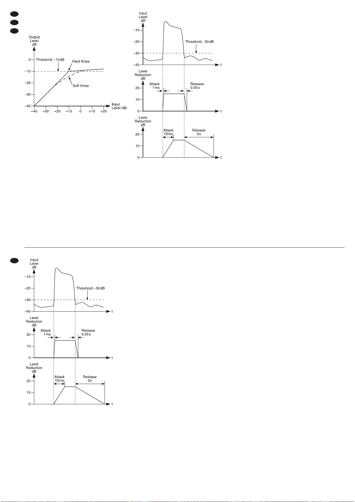
Figure 5 shows the function of a gate by means of an
input signal with a noise part and the “cleaned” out-
put signal.
Gate at a threshold of
-
30 dB
1) Set the button BYPASS/COMP (23) to COMP
(engage it). The button will light up; thus, the sig-
nal processing will be activated.
2) Adjust the threshold of the expander with the con-
trol THRESHOL (12). First turn the control to the
left stop (position OFF). The expander will be with-
out effect and all signals will be audible. Slowly
turn the control clockwise until the expander will
only allow the wanted signal (instrument or voice)
to pass through and will suppress noise in pauses
between the wanted signal. The LE s (4) will indi-
cate if the level of the input signal is below (
-
) or
above (+) the threshold adjusted.
3) Adjust the expansion ratio, i. e. the degree of
attenuation below the threshold with the control
RATIO (13). The present attenuation of the out-
put level can be read off on the LE chains GAIN
RE UCTION (8). Figure 6 shows the output level
as a function of the input level at a threshold of
-
30 dB and different expansion ratios.
Control characteristic of an expander
at a threshold of
-
30 dB
ote: If the level of the noise is just below the level
of the wanted signal (e. g. for percussion micro-
phones), the gate will also be opened by the noise.
To prevent this, insert an equalizer via the
sidechain connections (chapter 5.3). Set the
equalizer to the typical frequency range of the
wanted signal (e. g. pitch of the drum). Thus, it will
be easier to suppress noise with other frequencies.
6.3 Adjusting the compressor
6.3.1 Threshold and ratio
Adjust the threshold of the compressor with the con-
trol THRESHOL (15) and the compression ratio
with the control RATIO (17).
Position “1”:
no compression
Position “4”:
The ratio is 4 : 1; an input level modification of
8 dB above the threshold will result in an output
level modification of 2 dB.
Position “∞”:
The compressor will operate as a signal limiter; the
output signal will roughly be limited to the value
adjusted with the control THRESHOL (15).
The VU-meter is useful for adjusting the threshold
and the ratio. In order to be able to read off the out-
put level on the LE VU-meter (10, 11), the button
OUT/IN (21) must not be pressed. The indication
GAIN RE UCTION (8) will indicate the level reduc-
tion when the threshold is exceeded.
Figure 7 shows the output level as a function of
the input level at a threshold of
-
10 dB and different
compression ratios.
Figure 8 shows an input signal and the resulting
output signal at a threshold of
-
10 dB and a com-
pression ratio of 2 : 1. Below the threshold, the signal
will remain unchanged; above it, it will be com-
pressed by a factor of 2.
8
GB
CH
A
DEine Anzeige von 0 dB auf der Pegelanzeige
entspricht jeweils dem gewählten Nennpegel
-
10 dBV bzw. +4 dBu.
6.2 Expander/Gate einstellen
Ein Expander verhält sich entgegengesetzt zum
Kompressor: Er vergrößert die ynamik eines
Audiosignals. Beim Einsatz im unteren Pegelbereich
(Abwärts-Expander) werden Signale unterhalb
eines einstellbaren Pegels noch leiser. amit lassen
sich Störsignale, die leiser als das Nutzsignal sind,
aber besonders in Nutzsignalpausen stören, gezielt
ausblenden. Rauschen, Brummen, Übersprechen
von anderen Kanälen oder der unerwünschte Klang
eines benachbarten Instruments bei einer Mikrofon-
abnahme kann so unterdrückt werden. Soll ein
Audiosignal komprimiert und anschließend in seiner
Lautstärke angehoben werden, ist es besonders
wichtig, die Störsignale mit einem Expander abzu-
schwächen, da diese sonst auch verstärkt würden.
Wie stark die Signale unterhalb der Schwelle
gedämpft werden, lässt sich mit dem Regler Ratio
einstellen. Bei einem Expander mit einem extrem
eingestellten Expansionsverhältnis spricht man von
einem Gate (= Tor, das sich nur zum urchlassen
des Nutzsignals öffnet). Als Effekt lässt sich mit
einem Gate auch der Ausklang eines Instruments
verkürzen.
ie Abbildung 5 zeigt die Arbeitsweise eines Gates
anhand eines Eingangssignals mit einem Störsig-
nalanteil (Noise) und des „gesäuberten“ Ausgangs-
signals.
Gate bei einem Schwellwert von
-
30 dB
1) ie Taste BYPASS/COMP (23) auf COMP stel-
len (hineindrücken). ie Taste leuchtet und die
Signalbearbeitung ist damit eingeschaltet.
2) Mit dem Regler THRESHOL (12) den Schwell-
wert des Expanders einstellen. Zuerst den Regler
ganz nach links drehen (Position OFF). er
Expander ist ohne Wirkung und alle Signale sind
zu hören. en Regler langsam so weit nach
rechts drehen, bis der Expander nur das Nutzsig-
nal (Instrument oder Stimme) unverändert durch-
lässt und in Pausen des Nutzsignals die Störge-
räusche unterdrückt. ie LE s (4) zeigen, ob der
Pegel des Eingangssignals unterhalb (
-
) oder
oberhalb (+) der eingestellten Schwelle liegt.
3) Mit dem Regler RATIO (13) das Expansionsver-
hältnis, d. h. den Grad der Abschwächung unter-
halb des Schwellwertes einstellen. ie aktuelle
ämpfung des Ausgangspegels kann an den
LE -Ketten GAIN RE UCTION (8) abgelesen
werden. ie Abbildung 6 zeigt den Ausgangspe-
gel in Abhängigkeit vom Eingangspegel bei
einem Schwellwert von
-
30 dB und verschiede-
nen Expansionsverhältnissen.
Steuerkennlinie des Expanders bei einem
Schwellwert von
-
30 dB
Hinweis: Liegt der Pegel der Störgeräusche nur
etwas unter dem des Nutzsignals (z. B. bei
Schlagzeugmikrofonen), wird das Gate auch
durch die Störgeräusche geöffnet. Um das zu
verhindern, kann ein Equalizer über die Side-
chain-Anschlüsse eingeschleift werden (Kap.
5.3). en Equalizer auf den typischen Frequenz-
bereich des Nutzsignals einstellen (z. B. Grund-
ton der Trommel). Störgeräusche mit anderen
Frequenzen lassen sich so besser unterdrücken.

6.3 Kompressor einstellen
6.3.1 Threshold und Ratio
en Einsatzpunkt (Schwellwert) des Kompressors
mit dem Regler THRESHOL (15) einstellen und
das Kompressionsverhältnis mit dem Regler RATIO
(17).
Position „1“:
Es erfolgt keine Kompression.
Position „4“:
as Verhältnis beträgt 4 : 1; eine Eingangspegel-
änderung von 8 dB oberhalb des Threshold-
Wertes bewirkt eine Ausgangspegeländerung
von 2 dB.
Position „∞“:
er Kompressor arbeitet als Signalbegrenzer;
das Ausgangssignal wird etwa auf den mit dem
Regler THRESHOL (15) eingestellten Wert be-
grenzt.
Zur Einstellung von Threshold und Ratio ist die
Pegelanzeige nützlich. Um den Ausgangspegel auf
der LE -Anzeige (10, 11) ablesen zu können, darf
die Taste OUT/IN (21) nicht gedrückt sein. ie
Anzeige GAIN RE UCTION (8) gibt beim Über-
schreiten des Schwellwertes die Pegelreduzierung
an.
ie Abbildung 7 zeigt den Ausgangspegel in Ab-
hängigkeit vom Eingangspegel bei einem Schwell-
wert von
-
10 dB und verschiedenen Kompressions-
verhältnissen.
ie Abbildung 8 zeigt ein Eingangssignal und das
resultierende Ausgangssignal bei einem Schwell-
wert von
-
10 dB und einem Kompressionsverhältnis
von 2 : 1. Unterhalb des Schwellwertes bleibt das
Signal unverändert und oberhalb wird es um den
Faktor 2 komprimiert.
Steuerkennlinien für den Kompressor bei einem
Schwellwert von
-
10 dB
Ein- und Ausgangssignal bei Threshold =
-
10 dB
und Ratio = 2 :1
Einstelltipps:
a. Je höher der Schwellwert und je niedriger das
Kompressionsverhältnis eingestellt wird, desto
mehr bleibt die natürliche ynamik erhalten.
b. Am stärksten wird das Ausgangssignal kompri-
miert, wenn der Regler THRESHOL (15) auf
-
40 dB gedreht wird und der Regler RATIO (17)
auf ∞. Eine starke Kompression ist erforderlich,
um z. B. das Ausklingen eines Instruments zu
verlängern (Sustain-Verlängerung) oder um eine
gleichmäßige Lautstärke bei Hintergrundmusik
zu erhalten.
c. Bei Gesangsmikrofonen wird der Regler THRES-
HOL (15) meistens auf einen niedrigen Wert
eingestellt, um eine Kompression des gesamten
Signals zu erhalten. Bei Instrumentenmikrofonen
wird der Regler THRESHOL (15) meistens auf
einen höheren Wert eingestellt, um nur die Sig-
nalspitzen zu komprimieren.
6.3.2 Ausgangspegel
urch die ynamikkompression verringert sich die
Ausgangslautstärke. Mit dem Regler OUTPUT
GAIN (22) kann die Reduzierung wieder ausgegli-
chen werden.
Zum Vergleich von Eingangs- und Ausgangspe-
gel kann die Pegelanzeige (10, 11) mit der Taste
OUT/IN (21) entsprechend umgeschaltet werden.
en Ausgangspegel des Kompressors an den Ein-
gangspegel des nachfolgenden Gerätes mit dem
Regler OUTPUT GAIN anpassen.
6.3.3 Weicher oder harter Einsatzpunkt
Ist die Taste SOFT (7) nicht gedrückt, erfolgt die
Kompression ab dem Schwellwert abrupt. as klingt
bei großen Pegelsprüngen sehr unnatürlich. Ande-
rerseits kann dieses aber auch ein beabsichtigter
Effekt sein. amit die Kompression sanft einsetzt
Control characteristics for the compressor
at a threshold of
-
10 dB
Input signal and output signal at threshold =
-
10 dB
and ratio = 2 :1
Hints concerning adjustment:
a. The higher the threshold and the lower the com-
pression ratio, the more natural the dynamics.
b. The output signal will be compressed to the high-
est extent when the control THRESHOL (15) is
set to
-
40 dB and the control RATIO (17) to ∞. A
high compression is required, for example, to
extend the final sound of an instrument (sustain
extension) or to obtain a constant volume with
background music.
c. With vocal microphones, the control THRESH-
OL (15) is usually set to a lower value to obtain
a compression of the complete signal. With
instrument microphones, the control THRESH-
OL (15) is usually set to a higher value to com-
press the signal peaks only.
6.3.2 Output level
ue to the dynamic compression, the output level
will be reduced. This reduction can be compensated
with the control OUTPUT GAIN (22).
For comparing the input level and the output
level, switch over the VU-meter (10, 11) accordingly
with the button OUT/IN (21). Match the output level
of the compressor to the input level of the following
unit with the control OUTPUT GAIN.
6.3.3 Soft/hard knee
When the button SOFT (7) is not pressed, the com-
pression from the threshold will be abrupt. With
greater changes in level, the sound will be most
unnatural. However, it may be an intentional effect.
For a soft and smooth start of the compression,
engage the button SOFT (7). Figure 9 shows the dif-
ference between a soft knee and a hard knee.
Soft/hard knee at threshold =
-
10 dB, ratio = 10 :1
6.3.4 Attack and release times, AUTO button
The attack and release times when the value
exceeds the threshold or falls below are adjustable.
When the button MANUAL/AUTO (19) is pressed,
these times will be automatically defined by the
audio signal. In this case, the controls ATTACK (18)
and RELEASE (20) will have no function.
If the desired result is not obtained with the auto-
matic setting, disengage the button MANUAL/AUTO
(19) and adjust the attack time of the compressor
with the control ATTACK (18) and the release time
with the control RELEASE (20). Figure 10 illustrates
the effect the two controls will have on the signal
reduction.
9
GB
CH
A
D
10
Controls ATTACK and RELEASE
Hints concerning adjustment:
a. When processing voices, a relatively long attack
time will be required so that the voice will not lose
in power. In this case, high level peaks will only
occur after long vowels. By contrast, set the con-
trol RELEASE to a short time. Thus, the begin-
ning of the next syllable will not be attenuated.
b. Short attack times will be required for percussion
instruments as the highest volume will occur at
the start of a percussion.
c. For bass compression, adjust longer attack and
release times. If these times are too short, distor-
tions will result.
d. Longer release times will be required for instru-
ments played in a very dynamic way, such as
electric guitars. A short release time would
smooth out tremolo variations. To compress the
stereo master of a mixer, also adjust a longer
release time; otherwise the level of the signal will
be decreased and immediately increased again
in case of a volume peak. A “pumping effect” will
result.
e. The optimum attack and release times largely
depend on the type of application and will require
both intuition and experience. ifferent settings
should be tested.
6.4 Adjusting the limiter
Independent of the expander and the compressor,
the limiter will monitor the output level and limit the
signal to a maximum value adjusted. Thus, it will be
possible, e. g. to protect audio recordings and power
amplifiers against overload and speakers against
damage. Short upper deviations from the level
adjusted will be radically limited; in case of longer
deviations, the level of the entire signal will be
reduced.
Adjust the maximum admissible output level with
the control THRESHOL (24). In case of limiting, the
LE LIMITER (9) will light up. In addition, the reduc-
tion of the level will be shown by the indication GAIN
RE UCTION (8).
If the LE LIMITER lights up frequently, the level
should be generally reduced a little with the control
OUTPUT GAIN (22) or a higher compression should
be adjusted.
6.5 SIDECHAI FILTER
When the button SC FILTER is pressed, the control
signal for signal processing will pass a high-pass fil-
ter. This will reduce a “pumping effect” which may
occur in bass-accented music where the bass notes
cause a pulsed compression of the entire signal.
6.6 Sidechain applications
A sidechain is the circuit of the control signal. Usu-
ally the control signal will directly be derived from the
audio signal and will affect the output level, depend-
ing on the values adjusted for the expander, the
compressor and the limiter.
This control signal may additionally be processed
externally before it monitors the dynamics of the
audio signal or an external signal may be used for
control. Examples of application can be found below.
6.6.1 Frequency-dependent dynamics
de-esser, expander/gate
To suppress sibilance with voice recordings, insert
an equalizer via the jacks SI ECHAIN SEN (33)
and RETURN (34) [chapter 5.3].
1) Engage the button SC EXT (5) so that the signal
processed externally will take control.
2) Adjust the equalizer as a band-pass filter in such
a way that only frequencies in the range 6 –8kHz
will pass through.
To check the control signal acoustically, press
the button SC MONITOR (14) to switch it to the
output.
Thus, the compressor will operate as a “de-esser” to
attenuate sibilant sound.
In the same way, the expander/gate section can
be controlled via a band-pass filter matched to the
corresponding instrument, e. g. to improve channel
separation when several microphones are used.
GB
CH
A
Dund somit unauffälliger wird, die Taste SOFT (7)
hineindrücken. ie Abbildung 9 veranschaulicht den
Unterschied zwischen weichem und hartem Einsatz-
punkt.
weicher/harter Einsatzpunkt bei
Threshold =
-
10 dB, Ratio = 10 :1
6.3.4 Attack- und Release-Zeit, AUTO-Taste
ie Reaktionszeiten beim Überschreiten und Unter-
schreiten des Schwellwertes können eingestellt wer-
den. Ist die Taste MANUAL/AUTO (19) gedrückt,
werden diese Zeiten automatisch anhand des
Audiosignals bestimmt. ie Regler ATTACK (18)
und RELEASE (20) sind dann ohne Funktion.
Wird mit der automatischen Einstellung nicht das
gewünschte Ergebnis erzielt, die Taste MANUAL/
AUTO (19) ausrasten und mit dem Regler ATTACK
(18) die Ansprechzeit des Kompressors einstellen
sowie mit dem Regler RELEASE (20) die Rückstell-
zeit. ie Abbildung 10 verdeutlicht den Einfluss der
beiden Regler auf die Signalreduktion.
Regler ATTACK und RELEASE
Einstelltipps:
a. Bei der Bearbeitung von Stimmen ist eine relativ
lange Attack-Zeit notwendig, damit die Stimme
nicht an Kraft verliert. Hohe Pegelspitzen treten
hier erst nach längeren Vokalen auf. en Regler
RELEASE dagegen auf eine kurze Zeit einstel-
len. So wird der Anfang der nächsten Silbe nicht
gedämpft.
b. Kurze Attack-Zeiten werden bei Schlaginstru-
menten benötigt, weil die größte Lautstärke am
Anfang eines Schlags auftritt.
c. Bei der Kompression von Bässen längere Attack-
und Release-Zeiten einstellen. Zu kurze Zeiten
führen hier zu Verzerrungen.
d. Längere Release-Zeiten sind bei sehr dynamisch
gespielten Instrumenten erforderlich, z. B. bei E-
Gitarren. Eine kurze Release-Zeit würde Tre-
molo-Schwankungen glätten. Zum Komprimieren
der Stereo-Summe eines Mischpultes ebenfalls
eine längere Release-Zeit einstellen, sonst wird
das Signal bei einer Lautstärkespitze herunter-
und sofort wieder heraufgeregelt. Ein „Pump-
effekt“ entsteht.
e. ie optimale Attack- und Release-Zeit ist stark
anwendungsabhängig. Fingerspitzengefühl und
Erfahrung sind hier erforderlich. Verschiedene
Einstellungen sollten ausprobiert werden.
6.4 Limiter einstellen
Unabhängig von Expander und Kompressor über-
wacht der Limiter den Ausgangspegel und begrenzt
das Signal auf einen eingestellten Maximalwert.
adurch können z. B. Tonaufnahmen und Endstu-
fen vor Übersteuerungen bewahrt und Lautsprecher
vor Beschädigung geschützt werden. abei werden
kurze Überschreitungen des eingestellten Pegels
radikal begrenzt, bei länger dauernden Überschrei-
tungen wird das gesamte Signal im Pegel reduziert.
Mit dem Regler THRESHOL (24) den maximal
zulässigen Ausgangspegel einstellen. Findet eine
Begrenzung statt, leuchtet die LE LIMITER (9).
Zusätzlich wird die Reduzierung des Pegels mit der
Anzeige GAIN RE UCTION (8) dargestellt.
Leuchtet die LE LIMITER häufig auf, sollte der
Pegel mit dem Regler OUTPUT GAIN (22) generell
etwas gesenkt oder eine höhere Kompression ein-
gestellt werden.
6.5 SIDECHAI FILTER
Ist die Taste SC FILTER gedrückt, durchläuft das
Steuersignal für die Signalbearbeitung ein Hoch-

passfilter. ies vermindert einen „Pumpeffekt“, der
bei bassbetonter Musik entstehen kann, wenn auf-
grund der Basstöne das gesamte Signal impulsartig
komprimiert wird.
6.6 Sidechain-Anwendungen
Als Sidechain wird der Schaltkreis des Steuersig-
nals bezeichnet. as Steuersignal wird normaler-
weise direkt aus dem Audiosignal abgeleitet und
beeinflusst den Ausgangspegel, abhängig von den
eingestellten Werten für Expander, Kompressor und
Limiter.
ieses Steuersignal kann zusätzlich auch extern
bearbeitet werden, bevor es die ynamik des Audio-
signals kontrolliert oder es kann ein Fremdsignal für
die Steuerung herangezogen werden. Im Folgenden
werden dafür Anwendungsbeispiele beschrieben.
6.6.1 Frequenzabhängige Dynamik
De-Esser, Expander/Gate
Zur Unterdrückung von Zischlauten bei Sprachauf-
nahmen einen Equalizer über die Buchsen SI E-
CHAIN SEN (33) und RETURN (34) einschleifen
(Kap. 5.3).
1) ie Taste SC EXT (5) hineindrücken, damit das
extern bearbeitete Signal die Steuerung über-
nimmt.
2) en Equalizer als Bandpassfilter so einstellen,
dass nur Frequenzen im Bereich 6 – 8 kHz durch-
gelassen werden.
Zur akustischen Kontrolle des Steuersignals
kann dieses durch rücken der Taste SC MONI-
TOR (14) auf den Ausgang geschaltet werden.
er Kompressor arbeitet so als „ e-Esser“ zur
ämpfung von S-Lauten.
Auf die gleiche Art kann, z. B. zur besseren
Kanaltrennung beim Einsatz mehrerer Mikrofone,
die Expander/Gate-Sektion über ein auf das jewei-
lige Instrument abgestimmtes Bandpassfilter ge-
steuert werden.
6.6.2 Fremdgesteuerte Dynamik
Ducker, Expander/Gate
Beim ucker wird das Audiosignal in Abhängigkeit
von einem Fremdsignal komprimiert. Ein Mikrofon-
signal soll z. B. bei einer Moderation ein Musiksignal
herunterregeln. as Mikrofonsignal auf ein Misch-
pult und nach der Vorverstärkung zusätzlich auf die
Buchse SI ECHAIN RETURN (34) geben. as
Musiksignal am Kompressoreingang anschließen.
en Kompressorausgang auf einen zweiten Misch-
pulteingang legen.
Einstellungen am Kompressor:
1) ie Taste SC EXT (5) hineindrücken, damit das
externe Signal die Steuerung übernimmt.
2) Mit dem Regler THRESHOL (15) einstellen, ab
welcher Mikrofonlautstärke das Musiksignal ab-
gesenkt werden soll.
3) Mit dem Regler RATIO (17) die Stärke der Musik-
absenkung einstellen.
4) ie Taste MANUAL/AUTO (19) auf MANUAL
stellen (ausrasten) und mit dem Regler ATTACK
(18) eine kurze Attack-Zeit einstellen, damit das
Musiksignal sofort beim Sprechen abgesenkt
wird.
5) Mit dem Regler RELEASE (20) die Zeit einstel-
len, die verstreichen soll, bis nach einer Mikro-
fondurchsage die Musik wieder die normale Laut-
stärke erreicht (weiches Einblenden).
6) Zur akustischen Kontrolle des Steuersignals
kann dieses durch rücken der Taste SC MONI-
TOR (14) auf den Ausgang geschaltet werden.
Ebenso kann die Expander/Gate-Sektion über ein
Fremdsignal gesteuert werden. Es kann beispiels-
weise als Effekt zur Rhythmusbetonung ein Basston
durch den Schlag einer Bassdrum (über den Ein-
gang SI ECHAIN RETURN) synchronisiert werden.
Hinweise:
– Ist die Buchse SI ECHAIN RETURN (34) nicht
belegt, steuert unabhängig von der Schalterposi-
tion SC EXT (5) immer das interne Sidechain-Sig-
nal die ynamik.
– ie Eingänge SI ECHAIN SEN (33) und die
Ausgänge SI ECHAIN RETURN (34) werden
nicht durch rücken der Schalter +4 dBu /
-
10 dBV (30) auf den Pegel
-
10 dBV angepasst.
6.6.2 Externally controlled dynamics
ducker, expander/gate
With a ducker, the audio signal will be compressed
as a function of an external signal. For reducing a
music signal depending on a microphone signal,
e. g. for a presentation: Feed the microphone signal
to a mixer and, after preamplification, also to the jack
SI ECHAIN RETURN (34). Connect the music sig-
nal to the compressor input. Apply the compressor
output to the second input of the mixer.
Adjustments on the compressor:
1) Engage the button SC EXT (5) so that the exter-
nal signal will take control.
2) With the control THRESHOL (15) adjust the
microphone volume from which the music signal
is to be attenuated.
3) Adjust the music attenuation with the control
RATIO (17).
4) Set the button MANUAL/AUTO (19) to MANUAL
(disengage it) and adjust a short attack time with
the control ATTACK (18) so that the music signal
will be attenuated immediately when talking.
5) With the control RELEASE (20), adjust the time
until the music will reach its normal volume again
after a microphone announcement (soft fade-in).
6) To check the control signal acoustically, press the
button SC MONITOR (14) to switch it to the out-
put.
The expander/gate section can be controlled via an
external signal in the same way. As an effect to
emphasize the rhythm, e. g. a bass note can be syn-
chronized with the beat of a bass drum (via the input
SI ECHAIN RETURN).
otes:
– If the jack SI ECHAIN RETURN (34) is not used,
the internal sidechain signal will always control the
dynamics, regardless of the switch position SC
EXT (5).
– The inputs SI ECHAIN SEN (33) and the out-
puts SI ECHAIN RETURN (34) will not be
matched to the level
-
10 dBV when the switch
+4 dBu /
-
10 dBV (30) is pressed.
11
D
A
CH
GB

7 Technische Daten
Frequenzbereich: . . . . . . . 20 – 20 000 Hz,
-
0,5 dB
Nennpegel, umschaltbar: . 1,23 V/316 mV
(+4 dBu /
-
10 dBV)
Störabstand: . . . . . . . . . . . > 90 dB
Übersprechdämpfung: . . . > 100 dB
Klirrfaktor: . . . . . . . . . . . . . 0,01 % typ. bei 1 kHz
und +4 dBu Ausgangs-
pegel
Eingänge
Max. Eingangspegel, Impedanz, Anschluss
INPUT: . . . . . . . . . . . . . . . 8,7 V, 50 kΩ
XLR-Anschluss
6,3-mm-Klinkenanschluss (alternativ)
SI ECHAIN RETURN: . . . 12,3 V, > 10 kΩ
6,3-mm-Klinkenanschluss
Ausgänge
Max. Ausgangspegel, Impedanz, Anschluss
OUTPUT: . . . . . . . . . . . . . 8,7 V, 60 Ω
XLR-Anschluss
6,3-mm-Klinkenanschluss
SI ECHAIN SEN : . . . . . 8,7 V, 2 kΩ
6,3-mm-Klinkenanschluss
Expansion: . . . . . . . . . . . . 1,2 : 1 bis 8 :1
Kompression: . . . . . . . . . . 1:1 bis ∞ :1
Ansprechzeit (ATTACK): . . 1 – 150 ms
AUTO: . . . . . . . . . . . . . . 15 ms/10 dB
5 ms/20 dB
3 ms/30 dB
Rückstellzeit (RELEASE): . 0,05 – 5s
AUTO: . . . . . . . . . . . . . . 125 dB/s
Verstärkung: . . . . . . . . . . .
-
20 dB bis +20 dB
Limiter
Ansprechzeit: . . . . . . . . <5ms
Rückstellzeit: . . . . . . . . . typ. 20 dB/s
Stromversorgung: . . . . . . . 230 V~ / 50 Hz / 20 VA
Einsatztemperatur: . . . . . . 0 – 40 °C
Abmessungen: . . . . . . . . . 482 × 44 × 220 mm,
1 HE (Höheneinheit)
Gewicht: ..............3kg
Änderungen vorbehalten.
T = Signal +
R = Signal
-
S = Masse
1 = Masse
2 = Signal +
3 = Signal
-
T = Signal
S = Masse
T = Signal +
R = Signal
-
S = Masse
1 = Masse
2 = Signal +
3 = Signal
-
T = Signal
S = Masse
7 Specifications
Frequency range: . . . . . . . 20 – 20 000 Hz,
-
0.5 dB
Rated level, switchable: . . 1.23 V/316 mV
(+4 dBu /
-
10 dBV)
S/Nratio:..............>90dB
Crosstalk attenuation: . . . . > 100 dB
TH : .................0.01%typ.at1kHz
and +4 dBu output level
Inputs
Max. input level, impedance, connection
INPUT: . . . . . . . . . . . . . . . 8.7 V, 50 kΩ
XLR jack
6.3 mm plug (alternatively)
SI ECHAIN RETURN: . . . 12.3 V, > 10 kΩ
6.3 mm plug
Outputs
Max. output level, impedance, connection
OUTPUT: . . . . . . . . . . . . . 8.7 V, 60 Ω
XLR jack
6.3 mm plug
SI ECHAIN SEN : . . . . . 8.7 V, 2 kΩ
6.3 mm plug
Expansion: . . . . . . . . . . . . 1.2 : 1 to 8 :1
Compression: . . . . . . . . . . 1:1 to ∞ :1
ATTACK time: . . . . . . . . . . 1–150 ms
AUTO: . . . . . . . . . . . . . . 15 ms/10 dB
5 ms/20 dB
3 ms/30 dB
RELEASE time: . . . . . . . . . 0.05 –5s
AUTO: . . . . . . . . . . . . . . 125 dB/s
Amplification: . . . . . . . . . . .
-
20 dB to +20 dB
Limiter
Attack time: . . . . . . . . . . < 5 ms
Release time: . . . . . . . . typ. 20 dB/s
Power supply: . . . . . . . . . . 230 V~ / 50Hz / 20 VA
Ambient temperature: . . . . 0–40 °C
imensions: . . . . . . . . . . . 482 × 44 × 220 mm,
1 RS (rack space)
Weight: ...............3kg
Subject to technical modification.
T = signal
S = ground
T = signal +
R = signal
-
S = ground
1 = ground
2 = signal +
3 = signal
-
T = signal
S = ground
T = signal +
R = signal
-
S = ground
1 = ground
2 = signal +
3 = signal
-
12
D
A
CH
GB
iese Bedienungsanleitung ist urheberrechtlich für MONACOR
®
INTERNATIONAL GmbH & Co. KG
geschützt. Eine Reproduktion für eigene kommerzielle Zwecke – auch auszugsweise – ist untersagt.
All rights reserved by MONACOR
®
INTERNATIONAL GmbH & Co. KG. No part of this instruction manual
may be reproduced in any form or by any means for any commercial use.

13

Table des matières
1 Eléments et branchements ...........14
1.1 Faceavant .........................14
1.2 Panneau de commande canal A . . . . . . . . 14
1.3 Facearrière ........................15
2 Conseils dʼutilisation et de sécurité ....15
3 Possibilités dʼutilisation .............16
4 Possibilités dʼinstallation ............16
5 Branchements de lʼappareil ...........16
5.1 Insertion du compresseur dans un canal
detabledemixage ...................16
5.2 Insertion du compresseur entre
deuxappareilsaudio .................17
5.3 Utilisation des connexions Sidechain
(chaînelatérale) .....................17
5.4 Alimentation ........................17
6 Utilisation .........................17
6.1 Réglage du niveau correct de travail . . . . . 17
6.2 Réglage de lʼexpander/gate . . . . . . . . . . . . 18
6.3 Réglage du compresseur . . . . . . . . . . . . . . 19
6.3.1 Threshold et Ratio (seuil et rapport) . . . . 19
6.3.2 Niveaudesortie ...................19
6.3.3 Point dʼutilisation souple ou dur . . . . . . . 19
6.3.4 Temps dʼattaque et de rétablissement
(ATTACK, RELEASE), touche AUTO . . . 20
6.4 Réglagedulimiteur...................20
6.5 SI ECHAIN FILTER (filtre chaîne latérale) 21
6.6 Applications Sidechain . . . . . . . . . . . . . . . . 21
6.6.1 ynamique fonction de la fréquence
de-esser, expander/gate . . . . . . . . . . . . . 21
6.6.2 ynamique étrangère
ducker, expander/gate . . . . . . . . . . . . . . 21
7 Caractéristiques techniques ..........22
Ouvrez le présent livret page 3 de manière à
visualiser les éléments et branchements.
1 Eléments et branchements
1.1 Face avant
1Panneau de commande pour le canal A (détails,
schéma 2)
2Panneau de commande pour le canal B, corres-
pondant au canal A, seul le VU-mètre (11) se
trouve à gauche
3Interrupteur Marche/Arrêt POWER avec témoin
de fonctionnement
1.2 Panneau de commande canal A
4LE s +/
-
LE “+” : le signal dʼentrée est au-dessus du
seuil réglé est nʼest pas modifié
LE “
-
” : le signal dʼentrée est sous le seuil réglé
et est atténué par lʼexpander
5Touche SC EXT pour commuter le signal de
commande Sidechain
touche non enfoncée :
le signal dʼentrée est également utilisé comme
signal de commande pour le traitement de la
dynamique
touche enfoncée :
un signal présent à la prise SI ECHAIN
RETURN (34) est utilisé pour gérer le traite-
ment de la dynamique
Si la prise SI ECHAIN RETURN nʼest pas confi-
gurée, le signal de commande est toujours le
signal dʼentrée.
6LE s
-
/0/+
LE “+” : le signal dʼentrée est au-dessus du
seuil réglé et est modifié par le compresseur
LE “
-
” : le signal dʼentrée est au-dessous du
seuil réglé et nʼest pas modifié par le com-
presseur
LE “0” : si la touche SOFT (7) est enfoncée, le
signal dʼentrée est dans la plage de transition
autour du seuil réglé et est modifié par le com-
presseur avec le rapport de compression dimi-
nué
7Touche SOFT pour influer sur la gestion du com-
presseur
touche non enfoncée :
la compression démarre de manière dure
touche enfoncée :
la compression démarre de manière souple
(soft knee)
8VU-mètre à LE s pour lʼaffichage de la réduction
momentanée du niveau (compression)
9LE LIMITER : brille lorsque le signal de sortie
est limité par le limiteur
10 VU-mètre à LE s pour le signal dʼentrée et de
sortie du canal A ; 0 dB correspondent au niveau
nominal réglé avec lʼinterrupteur +4dBu/
-
10 dBV
(30).
11 VU-mètre à LE s pour le signal dʼentrée et de
sortie du canal B ; 0 dB correspondent au niveau
nominal réglé avec lʼinterrupteur +4dBu/
-
10 dBV
(30).
12 Réglage THRESHOL pour régler le seuil pour
lʼexpander : si le signal dʼentrée dépasse le seuil,
le signal peut passer, non modifié. Si on est en-
dessous, il est atténué avec le rapport RATIO
(13) réglé. En position OFF, le signal nʼest pas
modifié.
13 Réglage RATIO pour régler le rapport dʼexpan-
sion ; par exemple, pour un rapport de 4 : 1, une
diminution du niveau dʼentrée de 2 dB sous la
valeur du seuil conduit à une diminution du
niveau de sortie de 8 dB
Indice
1 Elementi di comando e collegamenti ...14
1.1 Latofrontale ........................14
1.2 Quadro di comando canale A . . . . . . . . . . . 14
1.3 Latoposteriore ......................15
2 Avvertenze di sicurezza ..............15
3 Possibilità dʼimpiego ................16
4 Possibilità di collocamento ...........16
5 Collegare lʼapparecchio ..............16
5.1 Inserire il compressore
inuncanaledelmixer.................16
5.2 Sistemare il compressore fra
dueapparecchiaudio .................17
5.3 Sfruttamento dei contatti sidechain . . . . . . 17
5.4 Alimentazione .......................17
6 Funzionamento .....................17
6.1 Impostazione del corretto livello di lavoro . . 17
6.2 Impostare Expander/Gate . . . . . . . . . . . . . 18
6.3 Impostare il compressore . . . . . . . . . . . . . . 19
6.3.1 Threshold e Ratio . . . . . . . . . . . . . . . . . . 19
6.3.2 Livellodʼuscita.....................19
6.3.3 Inserimento delicato o brusco . . . . . . . . . 19
6.3.4 Tempo di Attack e Release, tasto AUTO 20
6.4 Impostare il limiter . . . . . . . . . . . . . . . . . . . 20
6.5 FiltroSI ECHAIN ....................21
6.6 Applicazioni Sidechain . . . . . . . . . . . . . . . . 21
6.6.1 inamica dipendente dalla frequenza
e-ess, Expander/Gate . . . . . . . . . . . . . . 21
6.6.2 inamica comandata dallʼesterno
ucker, Expander/Gate . . . . . . . . . . . . . . 21
7 Dati tecnici ........................22
Vi preghiamo di aprire completamente la pagina
3. Così vedrete sempre gli elementi di comando
e i collegamenti descritti
1 Elementi di comando e collegamenti
1.1 Lato frontale
1Quadro di comando per il canale A (per partico-
lari vedi fig. 2)
2Quadro di comando per il canale B, corrisponde
al canale A, solo che lʼindicazione del livello (11)
si trova a sinistra
3Interruttore on/off POWER con spia di funziona-
mento
1.2 Quadro di comando canale A
4LE +/
-
LE “+”: il segnale dʼingresso è superiore al
valore di soglia impostato e rimane invariato
LE “
-
”: il segnale dʼingresso è inferiore al valore
soglia impostato e viene attenuato da parte
dellʼexpander
5Tasto SC EXT per cambiare il segnale di
comando Sidechain
Tasto non premuto:
il segnale dʼingresso è utilizzato anche come
segnale di comando per elaborare la dinamica
Tasto premuto:
un segnale presente alla presa SI ECHAIN
RETURN (34) è utilizzato per comandare lʼela-
borazione della dinamica
Se la presa SI ECHAIN RETURN è libera, il
segnale di comando è sempre il segnale dʼin-
gresso.
6LE
-
/0/+
LE “+”: il segnale dʼingresso è superiore al
valore di soglia impostato e viene modificato
dal compressore
LE “
-
”: il segnale dʼingresso è inferiore al valore
soglia impostato e non viene variato dal com-
pressore
LE “0”: il segnale dʼingresso si trova, se il tasto
SOFT (7) è premuto, intorno al valore soglia
impostato e viene variato dal compressore
con un rapporto ridotto di compressione
7Tasto SOFT per influenzare il comando del com-
pressore
Tasto non premuto:
la compressione si avvia bruscamente
Tasto premuto:
la compressione si avvia delicatamente (soft
knee)
8Spia a LE per la riduzione attuale del livello
(compressione)
9LE LIMITER, si accende se il segnale dʼuscita
è limitato dal limiter
10 Indicazione del livello a LE per il segnale dʼin-
gresso o dʼuscita del canale A; 0 dB corrisponde
al livello nominale impostato con lʼinterruttore
+4 dBu/
-
10 dBV (30)
11 Indicazione del livello a LE per il segnale dʼin-
gresso o dʼuscita del canale B; 0 dB corrisponde
al livello nominale impostato con lʼinterruttore
+4 dBu/
-
10 dBV (30)
12 Regolatore THRESHOL per impostare il valore
soglia per lʼexpander: se il segnale dʼingresso
supera il valore soglia, il segnale può passare in
modo invariato. Se rimane sotto il valore soglia
viene attenuato con il rapporto RATIO (13) impo-
stato. In posizione OFF, il segnale rimane inva-
riato.
13 Regolatore RATIO per impostare il rapporto
dʼespansione; per esempio, nel caso di un rap-
porto 4 : 1, la riduzione del livello dʼingresso di
2 dB sotto il valore soglia, comporta una ridu-
zione del livello dʼuscita di 8 dB
14
F
B
CH
I

14 Touche SC MONITOR pour le contrôle acous-
tique du signal de commande ; si la touche est
enfoncée, le signal de commande Sidechain est
appliqué à la sortie (28, 29) à la place du signal
traité
15 Réglage THRESHOL pour le compresseur ;
pour régler le point dʼutilisation (seuil) à partir
duquel le signal doit être comprimé
16 Touche SC FILTER pour allumer le filtre passe
haut pour le signal de commande Sidechain
17 Réglage RATIO pour régler le rapport de com-
pression :
position “1” :
aucune compression
position “4” :
le rapport est de 4 : 1 ; une modification du
niveau dʼentrée de 8 dB au-dessus du seuil
implique une modification du niveau de sortie
de 2 dB
position “∞” :
le compresseur fonctionne comme limiteur de
signal ; le niveau de sortie est limité environ à
la valeur réglée avec le réglage THRESHOL
(15)
18 Réglage ATTACK pour régler la durée de
réponse du compresseur
19 Sélecteur MANUAL/AUTO pour régler les
durées de compression
touche non enfoncée :
le réglage des potis ATTACK (18) et
RELEASE (20) détermine le temps dʼattaque
et de rétablissement du compresseur
touche enfoncée :
le temps dʼattaque et de rétablissement du
compresseur est déterminé automatiquement
en fonction du signal de musique
20 Réglage RELEASE pour régler le temps de réta-
blissement du compresseur
21 Commutateur OUT/IN pour le VU-mètre (10)
touche non enfoncée :
le signal de sortie est affiché
touche enfoncée :
le signal dʼentrée est affiché
22 Réglage OUTPUT GAIN pour régler le niveau de
sortie
23 Touche BYPASS/COMP
touche non enfoncée :
le signal dʼentrée arrive non modifié à la sortie
touche enfoncée :
le traitement du signal est actif
24 Réglage THRESHOL pour le limiteur ; pour
régler le niveau maximal auquel le signal doit
être limité
25 Touche UAL MONO / CH A MASTER pour
coupler les deux canaux
touche non enfoncée :
les deux canaux fonctionnent indépendam-
ment
touche enfoncée :
les réglages dans le canal A sont également
actifs pour le canal B (mode stéréo)
1.3 Face arrière
26 Prise secteur à brancher au secteur 230 V~/
50 Hz via le cordon secteur livré
27 Porte fusible : tout fusible fondu doit impérative-
ment être remplacé par un fusible de même type
28 Sorties, prises XLR
29 Sorties, prises jack 6,35
30 Commutateur +4 dBu /
-
10 dBV pour lʼadaptation
interne de niveau
position “+4 dBu” :
pour niveau ligne dans des utilisation en stu-
dio (+4 dBu = 1,23 V)
position “
-
10 dBV” :
pour niveau ligne dans des utilisations en
Home Recording (
-
10 dBV = 316 mV)
31 Entrées, prises XLR
32 Entrées, prises jack 6,35
33 Sorties SI ECHAIN SEN pour un traitement
externe du signal de commande (par exemple
égaliseur pour une compression en fonction de
la fréquence), prises jack 6,35 femelles
34 Entrées SI ECHAIN RETURN pour retourner le
signal de commande traité en externe ou pour la
gestion par des signaux étrangers, prises jack
6,35 femelles
2 Conseils dʼutilisation et de sécurité
Cet appareil répond à toutes les directives néces-
saires de lʼUnion européenne et porte donc le sym-
bole .
Respectez scrupuleusement les points suivants :
GLʼappareil nʼest conçu que pour une utilisation en
intérieur. Protégez-le de tout type de projections
dʼeau, des éclaboussures, dʼune humidité élevée
de lʼair et de la chaleur (plage de température de
fonctionnement autorisée : 0 – 40 °C).
GEn aucun cas, vous ne devez poser dʼobjet conte-
nant du liquide ou un verre sur lʼappareil.
GNe le faites jamais fonctionner et débranchez-le
immédiatement lorsque :
1. des dommages visibles apparaissent sur lʼap-
pareil ou sur le cordon secteur.
AVERTISSEME T Cet appareil est alimenté
par une tension dangereuse
230 V~. Ne touchez jamais
lʼintérieur de lʼappareil car,
en cas de mauvaise mani-
pulation, vous pourriez subir
une décharge électrique.
14 Tasto SC MONITOR per il controllo acustico del
segnale di comando; se il tasto è premuto, al
posto del segnale elaborato, allʼuscita (28, 29)
viene portato il segnale di comando Sidechain
15 Regolatore THRESHOL per il compressore;
per impostare il punto dʼinserzione (valore
soglia), a partire del quale il segnale deve essere
compresso
16 Tasto SC FILTER per attivare il filtro passa-alto
per il segnale di comando sidechain
17 Regolatore RATIO per impostare il rapporto di
compressione
posizione “1”:
nessuna compressione
posizione “4”:
il rapporto è 4 : 1; una variazione del livello
dʼingresso di 8 dB sopra il valore soglia com-
porta una variazione del livello dʼuscita di 2 dB
posizione “∞”:
îl compressore lavora come limitatore dei
segnali; il segnale dʼuscita è limitato allʼincirca
al valore impostato con il regolatore THRESH-
OL (15)
18 Regolatore ATTACK per impostare il tempo di
reazione del compressore
19 Commutatore MANUAL/AUTO per impostare i
tempi del compressore
Tasto non premuto:
lʼimpostazione dei regolatori ATTACK (18) e
RELEASE (20) determina il tempo di reazione
e di reset del compressore
Tasto premuto:
il tempo di reazione e di reset del compressore
è determinato automaticamente secondo il
segnale di musica
20 Regolatore RELEASE per impostare il tempo di
reset del compressore
21 Commutatore OUT/IN per lʼindicazione del livello
(10)
Tasto non premuto:
è visualizzato il segnale dʼuscita
Tasto premuto:
è visualizzato il segnale dʼingresso
22 Regolatore OUTPUT GAIN per impostare il
livello dʼuscita
23 Tasto BYPASS/COMP
Tasto non premuto:
il segnale dʼingresso arriva invariato allʼuscita
Tasto premuto:
è attiva lʼelaborazione del segnale
24 Regolatore THRESHOL per il limiter; per impo-
stare il livello massimo al quale deve essere limi-
tato il segnale
25 Tasto UAL MONO / CH A MASTER per accop-
piare i due canali
Tasto non premuto:
entrambi i canali funzionano in modo indipen-
dente
Tasto premuto:
le impostazioni nel canale A hanno effetto
anche per il canale B (funzionamento stereo)
1.3 Lato posteriore
26 Presa per il collegamento con una presa di rete
(230 V~/50 Hz) per mezzo del cavo rete in dota-
zione
27 Portafusibile
Sostituire un fusibile difettoso solo con uno dello
stresso tipo.
28 Uscite, prese XLR
29 Uscite, prese jack 6,3 mm
30 Commutatore +4 dBu/
-
10 dBV per lʼadattamento
interno del livello
posizione “+4 dBu”:
per livello Line nel settore studio di registra-
zione
(+4 dBu = 1,23 V)
posizione “
-
10 dBV”:
per livello Line nel settore del home-recording
(
-
10 dBV = 316 mV)
31 Ingressi, prese XLR
32 Ingressi, prese jack 6,3 mm
33 Uscite SI ECHAIN SEN per lʼelaborazione
esterna del segnale di comando (p. es. equaliz-
zatore per una compressione dipendente dalla
frequenza), prese jack 6,3 mm
34 Ingressi SI ECHAIN RETURN per riportare il
segnale di comando elaborato esternamente
oppure per il comando per mezzo di segnali
esterni, prese jack 6,3 mm
2 Avvertenze di sicurezza
Questʼapparecchio è conforme a tutte le direttive
richieste dellʼUE e pertanto porta la sigla .
Si devono osservare assolutamente anche i seguenti
punti:
GUsare lʼapparecchio solo allʼinterno di locali e pro-
teggerlo dallʼacqua gocciolante e dagli spruzzi
dʼacqua, da alta umidità dellʼaria e dal calore (tem-
peratura dʼimpiego ammessa fra 0 e 40 °C).
GNon depositare sullʼapparecchio dei contenitori
riempiti di liquidi, p. es. bicchieri.
GNon mettere in funzione lʼapparecchio e staccare
subito la spina rete se:
AVVERTIME TO Lʼapparecchio funziona con
pericolosa tensione di rete
(230 V~). Non intervenire mai
al suo interno. Esiste il pericolo
di una scarica elettrica.
15
I
F
B
CH

2. après une chute ou accident similaire..., vous
avez un doute au sujet de lʼétat de lʼappareil.
3. des dysfonctionnements apparaissent.
ans tous les cas, les dommages doivent être
réparés par un technicien spécialisé.
GNe débranchez jamais lʼappareil en tirant sur le
cordon secteur, tenez-le toujours par la fiche.
GPour le nettoyage utilisez uniquement un chiffon
doux et sec, en aucun cas de produits chimiques
ou dʼeau.
GNous déclinons toute responsabilité en cas de
dommages matériels ou corporels résultants si
lʼappareil est utilisé dans un but autre que celui
pour lequel il a été conçu, sʼil nʼest pas correcte-
ment branché, utilisé ou nʼest pas réparé par une
personne habilitée, en outre, la garantie devien-
drait caduque.
3 Possibilités dʼutilisation
Le compresseur/limiteur avec expander/gate est
conçu pour une utilisation professionnelle sur scène
et en studio. Il propose de nombreuses possibilités
pour traiter la dynamique dʼun signal audio.
La section expander/gate diminue le niveau
sous un seuil réglable et permet de prolonger la
dynamique du signal audio et dʼéliminer les signaux
perturbateurs bas. On peut également, comme effet,
réduire la fin des sons dʼun instrument.
Le compresseur diminue la dynamique et atté-
nue le niveau au-dessus dʼun seuil réglable. Cʼest
nécessaire lorsque la dynamique du signal audio est
supérieure à ce quʼun système dʼenregistrement ou
dʼamplificateur permet. e même, on peut diminuer
les différences de niveau (par exemple dans le cas
de distances changeantes de micros ou entre les dif-
férentes cordes dʼune guitare basse) ou atténuer
des crêtes de signal pour atteindre une meilleure
réglage de gain et donc un volume moyen plus
élevé. Comme effet, un compresseur peut être uti-
lisé pour modifier le comportement dʼun instrument
en ce qui concerne le début et la fin de ses sons.
Le limiteur sert pour limiter rapidement le signal
à un niveau réglé. Ainsi, des enregistrements audio
et étages finaux sont protégés contre les surcharges
ainsi que les haut-parleurs contre tout dégât.
Pour des applications spécifiques, par exemple
de-esser ou ducker, le signal de commande pris
depuis le signal audio peut être traité via les
connexions Sidechain en externe ou un signal étran-
ger peut être dirigé pour une gestion de la dyna-
mique.
Lʼappareil dispose de deux canaux identiques,
fonctionnant indépendamment et pouvant être cou-
plés pour un fonctionnement stéréo.
4 Possibilités dʼinstallation
Le compresseur est prévu pour une installation dans
un rack 482 mm/19" mais peut également être posé
sur une table. Pour le montage en rack, 1 unité est
nécessaire (1 unité = 44,45 mm).
5 Branchements de lʼappareil
Pour effectuer les branchements ou modifier les
branchements existants, éteignez tout dʼabord le
compresseur et les autres appareils reliés.
5.1 Insertion du compresseur dans un
canal de table de mixage
ans la majorité des cas dʼutilisation, le compres-
seur est inséré dans un canal dʼentrée, un sous
groupe ou la voie principale dʻune table de mixage
(connexion Insert). Pour ce faire, un cordon en Y
avec fiches jack 6,35 (par exemple MCA-202 de
MONACOR) est nécessaire par canal.
Cordon en Y MCA-202 pour la connexion INSERT
Effectuez le branchement pour les canaux A et B
séparément :
1) Mettez la fiche jack noire 3 pôles du cordon en Y
dans la prise Insert de la table de mixage.
2) Mettez la fiche jack noire 2 pôles dans la prise
INPUT (32) du compresseur.
3) Mettez la fiche jack rouge 2 pôles dans la prise
OUTPUT (29) du compresseur.
Attention : Sur la table de mixage, les signaux sur
la prise Insert peuvent être inversés par rapport au
schéma 4 : pointe = RETURN et anneau = SEN .
ans ce cas, les deux fiches jack 2 pôles sur le com-
presseur doivent être interverties : fiche noire
= OUTPUT, fiche rouge = INPUT.
On peut utiliser également les fiches XLR (28, 31) à
la place des fiches jack. Mais à cause des signaux
asymétriques des prises Insert, les Pin 1 et Pin 3 des
fiches XLR devraient être reliés dans ce cas.
MCL-204
INPUT
MCL-204
OUTPUT
Table de mixage
INSERT
Lorsque lʼappareil est définitivement retiré
du service, vous devez le déposer dans
une usine de recyclage adaptée pour
contribuer à son élimination non polluante.
1. lʼapparecchio o il cavo rete presentano dei
danni visibili;
2. dopo una caduta o dopo eventi simili sussiste il
sospetto di un difetto;
3. lʼapparecchio non funziona correttamente.
Per la riparazione rivolgersi sempre ad unʼofficina
competente.
GStaccare il cavo rete afferrando la spina, senza
tirare il cavo.
GPer la pulizia usare solo un panno morbido,
asciutto; non impiegare in nessun caso prodotti
chimici o acqua.
GNel caso dʼuso improprio, dʼimpiego scorretto, di
collegamenti sbagliati o di riparazione non a
regola dʼarte dellʼapparecchio, non si assume nes-
suna responsabilità per eventuali danni conse-
quenziali a persone o a cose e non si assume nes-
suna garanzia per lʼapparecchio.
3 Possibilità dʼimpiego
Il compressore/limiter con expander/gate è stato
realizzato per impieghi professionali sul palcosce-
nico e nello studio di registrazione. Lʼapparecchio
offre vaste possibilità per lʼelaborazione della dina-
mica del segnale audio.
La sezione expander/gate abbassa il livello al di
sotto di una soglia impostabile e offre la possibilità di
estendere la dinamica del segnale audio e di soppri-
mere interferenze a basso volume. Come effetto si
può accorciare il suono finale di uno strumento.
Il compressore riduce la dinamica e attenua il
livello al di sopra di una soglia impostabile. Questo
fatto è richiesto, quando la dinamica del segnale
audio è maggiore di quanto lo permette il sistema di
registrazione o di amplificazione. È possibile anche
ridurre delle differenze di livello (p. es. quando cam-
bia la distanza dal microfono o fra le singole corde di
una chitarra basso) oppure si possono attenuare i
picchi dei segnali per aumentare le possibilità di
regolazione e quindi per ottenere un maggiore
volume medio. Come effetto, un compressore può
essere usato per modificare il comportamento di
inserimento e di smorzamento di uno strumento
musicale.
Il limiter serve per limitare rapidamente il
segnale ad un livello impostato. In questo modo, per
le registrazioni audio e gli stadi finali si elimina il
sovrapilotaggio, e gli altoparlanti sono protetti dal
danneggiamento.
Per applicazioni speciali, come p. es. de-ess o
ducker, tramite i contatti sidechain, il segnale di
comando derivato dal segnale audio può essere ela-
borato esternamente oppure si può aggiungere un
segnale esterno per il comando della dinamica.
Lʼapparecchio dispone di due canali identici, che
funzionano indipendentemente, che tuttavia pos-
sono essere accoppiati per il funzionamento stereo
4 Possibilità di collocamento
Il compressore è previsto per il montaggio in un rack
(482 mm/19"), ma può essere usato anche come
apparecchio da tavolo. Per il montaggio in rack è
richiesta unʼunità dʼaltezza (= 44,45 mm).
5 Collegare lʼapparecchio
Per collegare o per modificare i collegamenti spe-
gnere dapprima il compressore e quindi tutti gli altri
apparecchi audio.
5.1 Inserire il compressore in
un canale del mixer
Nella maggiore parte delle applicazioni, il compres-
sore viene inserito in un canale dʼingresso, in un
sub-gruppo oppure nel percorso principale di un
mixer (contatto insert). In questo caso, per ogni
canale è richiesto un cavo ad Y con jack 6,3 mm
(p. es. MCA-202 di MONACOR).
Cavo ad Y, MCA-202 per il contatto INSERT
I collegamenti per i canali A e B si devono eseguire
separatamente:
1) Inserire il jack nero a 3 poli del cavo ad Y nella
presa Insert del mixer.
2) Inserire il jack nero a 2 poli nella presa INPUT
(32) del compressore.
3) Inserire il jack rosso a 2 poli nella presa OUTPUT
(29) del compressore.
Attenzione:
È possibile che nel mixer, alla presa
Insert, i segnali siano proprio opposti rispetto alla fig. 4:
punto = RETURN ed anello = SEN . In questo caso
occorre scambiare sul compressore i due jack a
2 poli: jack nero = OUTPUT e jack rosso = INPUT.
Al posto delle prese jack si possono collegare anche
le prese XLR (28, 31). A causa dei segnali asimme-
trici delle prese Insert, i pin 1 e 3 dei connettori XLR
dovrebbero essere collegati.
MCL-204
INPUT
MCL-204
OUTPUT
Mixer
INSERT
Se si desidera eliminare lʼapparecchio defi-
nitivamente, consegnarlo per lo smalti-
mento ad unʼistituzione locale per il rici-
claggio.
16
F
B
CH
I

5.2 Insertion du compresseur entre
deux appareils audio
Le compresseur peut être directement inséré entre
deux appareils audio (par exemple lecteur C ,
amplificateur professionnel). Le niveau de sortie de
la source de signal doit être sur niveau ligne, cʼest-
à-dire que lorsque vous branchez par exemple un
microphone, un préamplificateur micro doit être
branché avant. Les entrées et sorties du compres-
seur sont prévues sous forme de prises XLR et jack.
Les contacts des prises jack sont directement reliés
à ceux de la prise XLR correspondante.
Les prises sont configurées pour des signaux
symétriques. On peut également relier des sources
avec signaux asymétriques : le branchement doit
tout simplement se faire, pour les entrées ligne via
les fiches jack 2 pôles ; pour des entrées XLR, un
adaptateur est nécessaire : ses contacts XLR 1 et 3
y doivent être bridgés.
1) Reliez la sortie du canal gauche de la source de
signal (par exemple lecteur C ) à une des prises
INPUT (31 ou 32) du canal A du compresseur et
le canal droit de la source de signal à une des
prises INPUT du canal B.
2) Reliez une des prises OUTPUT (28 ou 29) du
canal A du compresseur à lʼentrée gauche du
canal de lʼappareil suivant (par exemple amplifi-
cateur professionnel) et une des prises OUTPUT
du canal B à lʼentrée droite de canal de lʼappareil
suivant.
5.3 Utilisation des connexions Sidechain
(chaîne latérale)
Les connexions Sidechain permettent de gérer le
compresseur via un signal traité en externe ou via un
signal étranger.
Si le compresseur doit être géré par un signal fil-
tré [par exemple si on lʼutilise comme de-esser pour
éliminer les chuintantes (chapitre 6.6.1)], un éga-
liseur doit être inséré sur les prises Sidechain.
1) Reliez la sortie SI ECHAIN SEN (33) à lʼentrée
de lʼégaliseur.
2) Reliez la sortie de lʼégaliseur où le signal traité est
présent, à lʼentrée SI ECHAIN RETURN (34).
Si le compresseur doit être géré par un signal étran-
ger (par exemple pour une utilisation comme ducker,
où la musique est automatiquement coupée pendant
une annonce, chapitre 6.6.2), reliez la source de
signal à lʼentrée SI ECHAIN RETURN (34).
5.4 Alimentation
Reliez le cordon secteur livré à la prise secteur (26)
et lʼautre extrémité du cordon à une prise 230 V~/
50 Hz.
6 Utilisation
A) Si le compresseur est utilisé pour traiter deux
sources distinctes de signal (par exemple deux
instruments ou deux microphones de chant), tous
les réglages pour le canal A et le canal B doivent
être effectués séparément. La touche UAL
MONO / CH A MASTER (25) ne doit pas être
enfoncée. ans le texte ci-dessous, sauf indica-
tion contraire, on parte toujours uniquement du
canal A, lʼutilisation du canal B est en tout point
identique.
B) Si un signal stéréo est traité (par exemple dʼun
lecteur C ), les canaux A et B doivent être gérés
de manière identique pour éviter tout déplace-
ment de balance. Enfoncez la touche UAL
MONO / CH A MASTER (25). Tous les réglages
se font maintenant uniquement via le panneau de
commande du canal A (1) et sont actifs pour les
deux canaux simultanément. Les interrupteurs
OUT/IN (21) qui permettent de commuter sépa-
rément les VU-mètres (10, 11) entre les signaux
dʼentrée et de sortie, les interrupteurs BYPASS/
COMP pour contourner le traitement des
signaux, les interrupteurs +4 dBu /
-
10 dBV (30)
pour lʼadaptation interne de niveau et les inter-
rupteurs Sidechain (5, 14, 16) sont lʼexception.
Le signal de commande est constitué par la
somme des signaux audio des deux canaux ; il
est important que les deux canaux soient réglés
sur le même niveau nominal +4 dBu /
-
10 dBV
(30).
6.1 Réglage du niveau correct de travail
1) Mettez lʼinterrupteur +4 dBu /
-
10 dBV (30) de la
face arrière sur +4 dBu (désenclenchez-le).
2) Allumez lʼappareil avec lʼinterrupteur POWER
(3), le témoin de fonctionnement sur lʼinterrupteur
brille.
3) Mettez la touche BYPASS/COMP (23) sur
BYPASS (désenclenchez-la). Le compresseur
est bridgé. Lorsquʼil est éteint, le compresseur est
également bridgé quelle que soit la position de
lʼinterrupteur. Une fois les autres appareils reliés
ou instruments allumés, on doit pouvoir les
entendre. Sinon, vérifiez les branchements.
4) Appuyez sur la touche OUT/IN (21). Le VU-mètre
(10, 11) indique le niveau dʼentrée. En cas de sur-
charge (les LE s rouges brillent tout le temps),
diminuez le niveau de sortie à la source de signal.
Si la déviation du VU-mètre est insuffisante,
appuyez sur le sélecteur pour le niveau nominal
(30) sur la face arrière de lʼappareil (position
-
10 dBV). Le niveau du signal est augmenté en
interne de 11,8 dB (4 dBu = 1,8 dBV). Le niveau
de sortie ne se modifie pas puisque le signal en
sortie est diminué en conséquence. Le niveau
dʼentrée sur la table de mixage ou le niveau de
sortie sur la source de signal doit éventuellement
être augmenté jusquʼà atteindre un contrôle opti-
mal.
Un affichage de 0 dB sur le VU-mètre corres-
pond respectivement au niveau nominal sélec-
tionné
-
10 dBV ou +4 dBu.
5.2 Sistemare il compressore fra
due apparecchi audio
Il compressore può essere sistemato anche diretta-
mente fra due apparecchi audio (p. es. lettore C e
amplificatore PA). Il livello dʼuscita della sorgente di
segnali deve essere Line , vuol dire che collegando
p. es. un microfono, occorre inserire prima un ampli-
ficatore per microfoni. Gli ingressi e le uscite del
compressore sono presenti come prese XLR e jack.
I contatti delle prese jack sono collegati direttamente
con i relativi contatti delle prese XLR.
Le prese sono predisposte per segnali simme-
trici. Tuttavia si possono collegare anche sorgenti
con segnali asimmetrici. In questo caso, il collega-
mento presso gli ingressi Line può essere fatto sem-
plicemente per mezzo di jack a 2 poli; per gli ingressi
XLR è richiesto un adattatore dove i contatti XLR 1 e
3 sono ponticellati.
1) Collegare lʼuscita del canale sinistro della sor-
gente (p. es. lettore C ) con una delle prese
INPUT (31 o 32) del canale A del compressore e
il canale destro della sorgente con una delle
prese INPUT del canale B.
2) Collegare una delle prese OUTPUT (28 o 29) del
canale A del compressore con lʼingresso del
canale sinistro dellʼapparecchio a valle (p. es.
amplificatore PA) e una delle prese OUTPUT del
canale B con lʼingresso del canale destro dellʼap-
parecchio a valle.
5.3 Sfruttamento dei contatti sidechain
I contatti sidechain servono per comandare il com-
pressore per mezzo di un segnale elaborato ester-
namente o di un segnale esterno.
Se il compressore deve essere comandato da un
segnale filtrato (p. es. nellʼuso come de-ess per sop-
primere i suoni sibilanti, Cap. 6.6.1) alle prese
sidechain si deve inserire un equalizzatore.
1) Collegare lʼuscita SI ECHAIN SEN (33) con
lʼingresso dellʼequalizzatore.
2) Collegare lʼuscita dellʼequalizzatore, dove è pre-
sente il segnale elaborato, con lʼingresso SI E-
CHAIN RETURN (34).
Se il compressore deve essere comandato da un
segnale esterno (p. es. per lʼimpiego come ducker,
dove la musica viene interrotta automaticamente
durante un avviso, Cap. 6.6.2), collegare la sor-
gente con lʼingresso SI ECHAIN RETURN (34).
5.4 Alimentazione
Inserire il cavo rete in dotazione nella presa (26) e la
sua spina in una presa di rete (230 V~/50 Hz).
6 Funzionamento
A) Se il compressore viene utilizzato per elaborare
due differenti sorgenti di segnali (p. es. due stru-
menti musicali o due microfoni per canto), tutte le
impostazioni per i canali A e B devono essere
eseguite separatamente. In questo caso, il tasto
UAL MONO / CH A MASTER (25) non deve
essere premuto. i seguito si descrive, salvo indi-
cazione differente, sempre solo il canale A. I
comandi per i canale B sono perfettamente iden-
tici.
B) Se viene elaborato un segnale stereo (p. es. di un
lettore C ), i canali A e B devono essere regolati
esattamente nello stesso modo per non aver
degli spostamenti del bilanciamento. A tale scopo
premere il tasto UAL MONO / CH A MASTER
(25). Tutte le impostazioni si fanno ora solo per
mezzo del quadro di comando del canale A (1),
ma hanno effetto su entrambi i canali. Unʼecce-
zione sono gli interruttori OUT/IN (21), con i quali
si cambiano le indicazioni del livello (10, 11) sin-
golarmente fra segnali dʼingresso e dʼuscita, gli
interruttori BYPASS/COMP per escludere lʼela-
borazione del segnale, gli interruttori +4 dBu/
-
10 dBV (30) per lʼadattamento interno del livello
nonché gli interruttori Sidechain (5, 14, 16).
Il segnale di comando è formato dalla somma
dei segnali audio di entrambi i canali. Perciò è
importante che tutti e due i canali siano regolati con
lo stesso livello nominale +4 dBu/
-
10 dBV (30).
6.1
Impostazione del corretto livello di lavoro
1) Portare lʼinterruttore +4 dBu/
-
10 dBV (30) sul
retro dellʼapparecchio su +4 dBu (sbloccarlo).
2) Accendere lʼapparecchio con lʼinterruttore
POWER (3). La spia di funzionamento sullʼinter-
ruttore si accende.
3) Portare il tasto BYPASS/COMP (23) su BYPASS
(sbloccarlo). Il compressore è bypassato. Se è
spento, il compressore, indipendentemente dalla
posizione dellʼinterruttore, è pure bypassato.
opo lʼaccensione degli altri apparecchi o stru-
menti collegati, questi si devono poter ascoltare.
Altrimenti controllare tutti i collegamenti.
4) Premere il tasto OUT/IN (21). Lʼindicazione di
livello (10, 11) indica ora il livello dʼingresso. In
caso di sovrapilotaggio (i LE rossi rimangono
accesi) ridurre il livello dʼuscita della sorgente.
Se la reazione dellʼindicazione del livello è
troppo scarsa, premere il selettore per il livello
nominale (30) sul retro dellʼapparecchio (posi-
zione
-
10 dBV). In questo modo, il livello del
segnale viene alzato internamente di 11,8 dB
(4 dBu = 1,8 dBV). Il livello dʼuscita non cambia,
dato che il segnale allʼuscita viene abbassato in
corrispondenza. Eventualmente occorre aumen-
tare il livello dʼingresso anche sul mixer o alla sor-
gente fino ad ottenere una regolazione ottimale.
Lʼindicazione di 0 dB per il livello corrisponde
al livello nominale scelto
-
10 dBV opp. +4 dBu.
17
I
F
B
CH

6.2 Réglage de lʼexpander/gate
Un expander se comporte à lʼopposé dʼun compres-
seur : il augmente la dynamique dʼun signal audio. Si
on lʼutilise dans la plage inférieure de niveau (expan-
der vers le bas), les signaux sous un niveau réglable
sont encore plus bas. Ainsi, on peut couper, de
manière ciblée, les signaux perturbateurs qui sont
plus bas que le signal utile et perturbent dans les
pauses du signal utile. On peut ainsi éliminer les
bruits, ronflements, diaphonies dʼautres canaux ou
une sonorité non voulue dʼun instrument voisin lors
dʼune prise de son par micro. Si un signal audio doit
être comprimé puis son volume augmenté, il est par-
ticulièrement important dʼatténuer les signaux per-
turbateurs avec un expander car sinon ils seraient
également amplifiés.
La puissance de lʼatténuation des signaux sous le
seuil peut être réglée avec le réglage Ratio. Pour un
expander avec un rapport dʼexpansion réglé à lʼex-
trême, on parle dʼun gate (= portail qui ne sʼouvre
que pour laisser passer le signal utile). Comme effet,
on peut réduire avec un gate, la fin des sons dʼun
instrument.
Le schéma 5 présente la méthode de travail dʼun
gate en fonction dʼun signal dʼentrée avec une part
de signal perturbateur (Noise) et du signal de sortie
“nettoyé”.
Gate pour un seuil de
-
30 dB
1) Mettez la touche BYPASS/COMP (23) sur COMP
(enfoncez-la). La touche brille, le traitement du
signal est ainsi activé.
2) Avec le réglage THRESHOL (12), réglez le
seuil de lʼexpander. Tout dʼabord, tournez le
réglage entièrement à gauche (position OFF).
Lʼexpander est sans effet, tous les signaux sont
audibles. Tournez lentement le réglage vers la
droite jusquʼà ce que lʼexpander ne laisse passer,
de manière non modifiée, que le signal utile (ins-
trument ou voix) et élimine dans les pauses du
signal utile, les bruits perturbateurs. Les LE s (4)
indiquent si le niveau du signal dʼentrée est au-
dessous (
-
) ou au-dessus (+) du seuil réglé.
3) Avec le réglage RATIO (13), réglez le rapport
dʼexpansion, cʼest-à-dire le degré de lʼatténuation
sous le seuil. Lʼatténuation actuelle du niveau de
sortie peut être lue sur les LE s GAIN RE UC-
TION (8). Le schéma 6 présente le niveau de sor-
tie en fonction du niveau dʼentrée pour un seuil de
-
30 dB et différents rapports dʼexpansion.
Caractéristique de lʼexpander pour un seuil de
-
30 dB
Remarque : Si le niveau des interférences se
trouve un peu sous le niveau du signal utile (par
exemple pour des microphones de batteries), le
gate est également ouvert par les bruits pertur-
bateurs. Pour éviter cela, un égaliseur peut être
inséré via les connexions Sidechain (chapitre
5.3). Réglez lʼégaliseur sur la plage typique de
fréquence du signal utile (par exemple hauteur du
son dʼun tambour). e cette manière, les bruits
perturbateurs avec dʼautres fréquences peuvent
être mieux éliminés.
6.2 Impostare lʼexpander/gate
Un expander si comporta in modo opposto rispetto al
compressore: aumenta la dinamica di un segnale
audio. Usandolo nei livelli bassi (expander decre-
scente), i segnali sotto un livello regolabile diventano
ancor più lievi. In questo modo è possibile eliminare
con precisione le interferenze che sono più deboli del
segnale utile, ma che disturbano nelle pause del
segnale utile. Così si può sopprimere il rumore, il ron-
zio, la diafonia da altri canali oppure il suono non
desiderato di uno strumento vicino durante la regi-
strazione con microfono. Se un segnale audio deve
essere compresso per aver successivamente il
volume aumentato, è particolarmente importante
attenuare le interferenze con un expander, dato che
altrimenti sarebbero amplificati anche le interferenze.
Lʼentità dellʼattenuazione dei segnali sotto la
soglia può essere impostata con il regolatore Ratio.
In caso di un expander con un rapporto estremo
dʼespansione, si parla di un gate (= porta che si apre
solo per far passare il segnale utile). Come effetto,
con un gate si può accorciare anche il suono finale
di uno strumento musicale.
La figura 5 illustra il funzionamento di un gate con un
segnale dʼingresso con una parte dʼinterferenze
(noise) e con il segnale dʻuscita “pulito”.
Gate con un valore soglia di
-
30 dB
1) Portare il tasto BYPASS/COMP (23) su COMP
(spingerlo). Il tasto sʼillumina e quindi lʼelabora-
zione del segnale è attiva.
2) Con il regolatore THRESHOL (12) impostare il
valore soglia dellʼexpander. apprima girare il
regolatore tutto a sinistra (posizione OFF). Lʼex-
pander è senza effetto e si possono ascoltare tutti
i segnali. Girare il regolatore lentamente a destra
finché passa invariato solo il segnale utile (stru-
mento musicale o voce) mentre nelle pause le
interferenze vengono soppresse. I LE (4) indi-
cano se il livello del segnale dʼingresso è sotto
(
-
) o sopra (+) la soglia impostata.
3) Con il regolatore RATIO (13) impostare il rap-
porto dʼespansione, cioè il grado dellʼattenua-
zione sotto il valore soglia. Lʼattenuazione attuale
del livello dʼuscita può essere letta dalla catena
dei LE GAIN RE UCTION (8). La figura 6 illu-
stra il livello dʼuscita a seconda del livello dʼin-
gresso con un valore soglia di
-
30 dB e con diffe-
renti rapporti dʼespansione.
Curva di comando dellʼexpander con un
valore soglia di
-
30 dB
18
F
B
CH
I

6.3 Réglage du compresseur
6.3.1 Threshold et Ratio (seuil et rapport)
Réglez le point dʼutilisation (seuil) du compresseur
avec le réglage THRESHOL (15) et le rapport de
compression avec le réglage RATIO (17).
Position “1” :
aucune compression
Position “4” :
le rapport est de 4 : 1. Une modification du niveau
dʼentrée de 8 dB au-dessus de la valeur du seuil
implique une modification du niveau de sortie de
2 dB.
Position “∞” :
le compresseur fonctionne comme limiteur de
signal : le signal de sortie est limité à peu près, à
la valeur réglée avec le réglage THRESHOL
(15).
Pour régler le Threshold et le Ratio, le VU-mètre est
utile. Pour pouvoir lire le niveau de sortie sur le VU-
mètre (10, 11), la touche OUT/IN (21) ne doit pas
être enfoncée. Lʼaffichage GAIN RE UCTION (8)
indique la réduction de niveau en cas de dépasse-
ment du seuil.
Le schéma 7 indique le niveau de sortie en fonc-
tion du niveau dʼentrée pour un seuil de
-
10 dB et
différents rapports de compression.
Le schéma 8 indique un niveau dʼentrée et le
signal de sortie résultant pour un seuil de
-
10 dB et
un rapport de compression de 2 : 1. Le signal reste
non modifié sous le seuil et il est comprimé du fac-
teur 2 au-dessus.
Caractéristique pour le compresseur pour
un seuil de
-
10 dB
Signal dʼentrée et de sortie pour Threshold =
-
10 dB et
Ratio = 2 :1
Trucs de réglage :
a. Plus le seuil est réglé de manière élevée et plus
le rapport de compression est réglé de manière
faible, plus la dynamique naturelle est conservée.
b. Le signal de sortie est comprimé de manière la
plus forte lorsque le réglage THRESHOL (15)
est tourné sur
-
40 dB et le réglage RATIO (17)
sur ∞. Une compression importante est néces-
saire pour par exemple prolonger la fin des sons
dʼun instrument (prolongement Sustain) ou pour
maintenir un volume équilibré pour la musique
dʼambiance.
c. Pour des microphones de chant, le réglage
TRESHOL (15) est réglé généralement sur une
valeur faible pour maintenir une compression du
signal complet. Pour des microphones à instru-
ments, le réglage THRESHOL (15) est généra-
lement réglé sur une valeur supérieure pour com-
primer uniquement les pointes de signal.
6.3.2 iveau de sortie
Le volume de sortie est diminué par la compression
de la dynamique. Avec le réglage OUTPUT GAIN
(22), on peut compenser la diminution.
Pour comparer le niveau dʼentrée et le niveau de
sortie, on peut commuter le VU-mètre (10, 11) avec
la touche OUT/IN (21), en fonction. Adaptez le
niveau de sortie du compresseur au niveau dʼentrée
de lʼappareil suivant avec le réglage OUTPUT GAIN.
6.3.3 Point dʼutilisation souple ou dur
Si la touche SOFT (7) nʼest pas enfoncée, la com-
pression sʼeffectue à partir du seuil de manière
abrupte. Cela sonne de manière très peu naturelle
pour de grands sauts de niveau. ʼun autre côté,
cela peut avoir un effet voulu. Pour que la compres-
sion démarre de manière douce et donc discrète,
enfoncez la touche SOFT (7). Le schéma 9 présente
la différence entre un point dʼutilisation souple et dur.
. B.: Se il livello delle interferenze è solo di poco
sotto quello del segnale utile (p. es. nel caso di un
microfono per batterie), il gate si apre anche con
le interferenze. Per evitare ciò, si può inserire un
equalizzatore per mezzo dei contatti sidechain
(Cap. 5.3). Impostare lʼequalizzatore secondo
le frequenze tipiche del segnale utile (p. es. nota
fondamentale del tamburo). In questo modo è più
facile sopprimere le interferenze con frequenze
differenti.
6.3 Impostare il compressore
6.3.1 Threshold e Ratio
Impostare il punto dʼinserzione (valore soglia) del
compressore con il regolatore THRESHOL (15) e il
rapporto di compressione con il regolatore RATIO
(17).
Posizione “1”:
Non si ha nessuna compressione.
Posizione “4”:
Il rapporto è 4 : 1; un cambio del livello dʼingresso
di 8 dB sopra il valore soglia comporta un cambio
del livello dʼuscita di 2 dB.
Posizione “∞”:
Il compressore funziona come limitatore del
segnale; il segnale dʼuscita viene limitato allʼin-
circa al valore impostato con il regolatore
THRESHOL (15).
Per lʼimpostazione di Threshold e Ratio è utile lʼindi-
cazione del livello. Per poter leggere il livello dʼuscita
sullʼindicazione con LE (10, 11), il tasto OUT/IN
(21) non deve essere premuto. Lʼindicazione GAIN
RE UCTION (8) indica la riduzione del livello se il
valore soglia viene superato.
La figura 7 illustra il livello dʼuscita a seconda del
livello dʼingresso con un valore soglia di
-
10 dB e
con differenti rapporti di compressione.
La figura 8 illustra il segnale dʼingresso e il con-
seguente segnale dʼuscita con un valore soglia di
-
10 dB e con un rapporto di compressione di 2 : 1.
Sotto il valore soglia, il segnale rimane invariato, e
sopra lo stesso viene compresso con il fattore 2.
Curve di comando per il compressore con un valore
soglia di
-
10 dB
Segnale dʼingresso e dʼuscita con Threshold =
-
10 dB
e Ratio = 2 :1
Consigli per lʼimpostazione:
a. Più si imposta alto il valore soglia e basso il rap-
porto di compressione, più si mantiene la dina-
mica naturale.
b. La più forte compressione del segnale dʼuscita si
ottiene se il regolatore THRESHOL (15) è girato
su
-
40 dB e il regolatore RATIO (17) su ∞. Una
forte compressione è necessaria, p. es. per allun-
gare il suono finale di uno strumento musicale
(prolungamento sustain) oppure per avere un
volume uniforme in caso di musica di sottofondo.
c. Con i microfoni per canti, il regolatore THRESH-
OL (15) viene generalmente messo su un
valore basso per avere una compressione dellʼin-
tero segnale. Con i microfoni per strumenti musi-
cali, il regolatore THRESHOL (15) viene gene-
ralmente messo sul un valore più alto per
comprimere solo i picchi del segnale.
6.3.2 Livello dʼuscita
Per via della compressione della dinamica si riduce
il volume allʼuscita. Con il regolatore OUTPUT GAIN
(22) tale riduzione può esser compensata.
Per confrontare il livello dʼingresso con quello
dʼuscita è possibile modificare in corrispondenza
lʼindicazione del livello (10, 11) per mezzo del tasto
OUT/IN (21). Adattare il livello dʼuscita del compres-
sore al livello dʼingresso dellʼapparecchio a valle ser-
vendosi del regolatore OUTPUT GAIN.
6.3.3 Inserimento delicato o brusco
Se il tasto SOFT (7) non è premuto, la compressione
avviene in modo brusco a partire dal valore soglia.
Ciò ha un effetto innaturale con grandi differenze dei
livelli. ʼaltra parte può trattarsi anche di un effetto
desiderato. Affinché la compressione si inserisca
delicatamente e in modo meno percepibile, premere
il tasto SOFT (7). La figura 9 illustra la differenza fra
punto dʼinserzione delicato e brusco.
19
I
F
B
CH

Point dʼutilisation souple/dur pour Threshold =
-
10 dB,
Ration = 10 :1
6.3.4 Temps dʼattaque et de rétablissement
(ATTACK, RELEASE), touche AUTO
On peut régler les durées de réaction si on est au-
dessus ou au-dessous du seuil. Si la touche
MANUAL/AUTO (19) est enfoncée, ces durées sont
automatiquement déterminées en fonction du signal
audio. Les réglages ATTACK (18) et RELEASE (20)
sont sans fonction.
Si on nʼatteint pas le résultat voulu avec le
réglage automatique, désenclenchez la touche
MANUAL/AUTO (19) et réglez le temps dʻattaque du
compresseur avec le réglage ATTACK (18) et le
temps de rétablissement avec le réglage RELEASE
(20). Le schéma 10 présente lʼinfluence des deux
réglages sur la réduction du signal.
Réglages ATTACK et RELEASE
Trucs de réglage :
a. Lors du traitement de voix, un temps dʼattaque
relativement long est nécessaire pour que la voix
ne perde pas en puissance. es crêtes de niveau
élevées nʼapparaissent quʼaprès des voyelles
longues. Réglez le réglage RELEASE, en
revanche, sur une durée courte. Ainsi le début de
la syllabe suivante ne sera pas atténué.
b. es temps dʼattaque brefs sont nécessaires pour
des instruments à percussions car le volume le
plus important apparaît au début dʼune percussion.
c. Pour la compression de graves, réglez des temps
dʼattaque et de rétablissement plus longs. es
durées courtes génèrent des interférences.
d. es durées de rétablissement plus longues sont
indispensables pour des instruments avec une
grande dynamique, par exemple des guitares
électriques. Un temps de rétablissement court
génèrerait des fluctuations de type trémolo. Pour
comprimer le master stéréo dʼune table de
mixage, réglez également un temps de rétablis-
sement plus long sinon le signal, pour des
pointes de volume, est réglé plus bas et immé-
diatement après plus fort. Un effet “Pump” (Pom-
page) est créé.
e. Le temps optimal dʼattaque et de rétablissement
dépend largement du type dʼutilisation. Lʼexpé-
rience et lʼintuition sont indispensables, de
même, il convient de procéder à différents types
de réglages.
6.4 Réglage du limiteur
Indépendamment de lʼexpander et du compresseur,
le limiteur surveille le niveau de sortie et limite le
signal à une valeur maximale réglée. Ainsi, on peut
protéger par exemple des enregistrements audio et
amplificateurs contre toutes surcharges et protéger
les haut-parleurs contre tout dommage. Ainsi, on
limite de manière radicale les brefs dépassements
du niveau réglé, pour des dépassements plus longs,
le niveau du signal complet est diminué.
Avec le réglage THRESHOL (24), réglez le
niveau de sortie maximal autorisé. Sʼil y a une limi-
tation, la LE LIMITER (9) brille. La réduction du
niveau est en plus signalée par lʼaffichage GAIN
RE UCTION (8).
Si la LE LIMITER brille souvent, le niveau de
sortie devrait être généralement un peu diminué
avec le réglage OUTPUT GAIN (22) ou une com-
pression plus importante devrait être réglée.
Punto dʼinserzione delicato/brusco con
Threshold =
-
10 dB, Ratio = 10 :1
6.3.4 Tempo di Attack e Release, tasto AUTO
I tempi di reazione in caso di superamento in alto o
in basso del valore soglia possono essere regolati.
Se il tasto MANUAL/AUTO (19) è premuto, questi
tempi sono determinati automaticamente sulla base
del segnale audio. I regolatori ATTACK (18) e
RELEASE (20) sono senza funzione in questo caso.
Se con lʼimpostazione automatica non si rag-
giunge il risultato desiderato, sbloccare il tasto
MANUAL/AUTO (19) e con il regolatore ATTACK
(18) impostare il tempo di reazione del compressore
e con il regolatore RELEASE (20) il tempo per il
reset. La figura 10 spiega lʼinfluenza dei due regola-
tori in merito alla riduzione del segnale.
Regolatori ATTACK e RELEASE
Consigli per lʼimpostazione:
a. urante lʼelaborazione di voci è richiesto un
tempo di attack relativamente lungo perché la
voce non perda di forza. Alti picchi di livello si
manifestano solo con vocali lunghi. Il regolatore
RELEASE invece va messo su un tempo breve.
In questo modo non si attenua lʼinizio della sillaba
successiva.
b.
Brevi tempi di attack sono richiesti per batterie, per-
ché il maggio volume si ha allʼinizio di ogni colpo.
c. Nella compressione di bassi conviene impostare
tempi più lunghi per attack e release. Tempi
troppo corti producono delle distorsioni.
d. Tempi di release più lunghi sono necessari con
strumenti suonati con forte dinamica, p. es. con
chitarre elettriche. Un breve tempo di release
appianerebbe le oscillazioni di tremolo. Per com-
primere la somma stereo di un mixer impostare
pure un tempo più lungo di release, altrimenti,
con un picco di volume, il segnale viene regolato
in basso e subito nuovamente in alto creando un
effetto di “pompaggio”.
e. Il tempo ottimale per attack e release dipende for-
temente dallʼapplicazione. Sono richieste sensi-
bilità e esperienza. Si dovrebbero fare delle prove
con differenti impostazioni.
6.4 Impostare il limiter
Indipendentemente dallʼexpander e dal compres-
sore, il limiter controlla il livello dʼuscita limitando il
segnale a una valore massimo impostato. In questo
modo, per esempio per le registrazioni audio e i finali
si elimina il sovrapilotaggio, e gli altoparlanti sono
protetti dal danneggiamento. Brevi superamenti del
livello impostato sono limitati radicalmente, mentre
per i superamenti prolungati si riduce il livello per lʼin-
tero segnale.
Impostare il livello dʼuscita massimo per mezzo
del regolatore THRESHOL (24). Se ha luogo una
limitazione, si accende il LE LIMITER (9). In più, la
riduzione del livello è rappresentata dallʼindicazione
GAIN RE UCTION (8).
Se il LE LIMITER si accende spesso, il livello
generale dovrebbe essere abbassato un poʼ per
mezzo del regolatore OUTPUT GAIN (22) oppure si
dovrebbe impostare una compressione maggiore.
20
F
B
CH
I
Other manuals for MCL-204
1
This manual suits for next models
1
Table of contents
Popular Air Compressor manuals by other brands


Ingersoll-Rand
Ingersoll-Rand XFE 50 Operators/Instruction Manual Options

Compressed Air Systems
Compressed Air Systems 15 HP Electric Reciprocating Compressor owner's manual

Champion
Champion PL Series Operation maintenance manual & parts list

Sealey
Sealey MAC1250 instructions

Craftsman
Craftsman 919.167361 owner's manual

Streetwize
Streetwize SWPP1 Instructions for use


