Impact Test Equipment AG250 User manual

www.impact-test.com
User Guide
User Guide
www.impact-test.com
www.impact-test.co.uk
www.impact-testsets.co.uk
Frost Heave Cabinet
AG250
Impact Test Equipment Ltd
www.impact-test.co.uk -www.impact-test.com
www.impact-testsets.co.uk

www.impact-test.co.uk www.impact-test.com www.impact-testsets.co.uk
Impact Test Equipment Ltd.
Building 21 Stevenston Ind. Est.
Stevenston
Ayrshire
KA20 3LR
T: 01294 602626
F: 01294 461168
E: sales@impact-test.co.uk
Test Equipment
www.impact-test.co.uk
Test Sieves & Accessories
www.impact-test.com
Test Sets to International Standards
www.impact-testsets.co.uk

www.impact-test.co.uk www.impact-test.com www.impact-testsets.co.uk
This equipment has been designed to meet the requirements of BS 812-124:2009
You will need to have a copy of this standard to refer to.
1. UNPACKING
1.1 Remove all packing material and place on a flat floor. It is important that the unit is level. Use the
self-levelling feet with an accurate spirit level instrument. Connect the drain to the fitting at the rear of
the Frost Heave. The Frost Heave is fitted with an automatic level filling system, however, with the nature
of the test, frost forms which condenses later and hence the unit will always be required to be connected
to the drain.
1.2 The unit has been pre-set to fill to 2mm below the samples, this can be adjusted by +/- 5 mm up
or down. To change the controlled fill height, adjust the framework holding the water tanks up and down
using the manual level control screws holding it in place. Raising the water framework will cause the
water level within the chamber to raise by the same amount. Alternatively, to lower the height, lower the
framework by that amount and then drain a little water out using the water drain valve.
www.impact-test.co.uk www.impact-test.com www.impact-testsets.co.uk
2. MAINS SUPPLY
2.1 240-volt units. Each unit comes supplied with a mains connection lead already fitted with a
correctly rated fuse. The fuse rating and other details for each unit is shown on the voltage plate riveted
to the back of the unit. It is important that, if the fuse needs to be replaced, it must only be replaced with
one of the correct rating. An integral RCD and MCB are also fitted within the control panel for added
electrical protection.
3. SET UP / OPERATION
3.1 Fill the top reserve tank with de ionised water and turn the unit on with the main black on/off
switch on the front panel.
3.2 Press the Level Control Button on the control panel. The screen should say ON and you will see
the water begin to fill into the bottom of the chamber. During filling, you will need to top of the reserve
water tank or the display will continuously state filling as will not get to the desired level. The system will
need around 45 litres of water to start. Refill the reserve tank with more de ionised water which will keep
the level constant during freezing and evaporation of the samples.
3.3 When the water level is close to the desired height, press the water pump button. If the button is
pressed too early, the display will change to Filling and only start to run when the level is high enough.
3.4 Check the height is correct as per the specification, if the level needs changing, follow step 1.2 in
chapter 1.
3.5 Position the lower 5 water probes in place using the guide bars. Follow the guide in BS 812-124
for the correct locations.
3.6 Place the wooden carry frame into the chamber
3.7 Place the test samples in the carry frame
www.impact-test.co.uk www.impact-test.com www.impact-testsets.co.uk
3.8 Position the 5 air probes into the top section of the chamber as per guidance from BS 812-124
3.9 Close lid, attached the upper frame and place the level guide rods through the 9 holes in the lid.
Connect your external displacement sensors to these guide rods (not supplied)
3.10 Leave the environment to settle as per guidance from BS 812-124
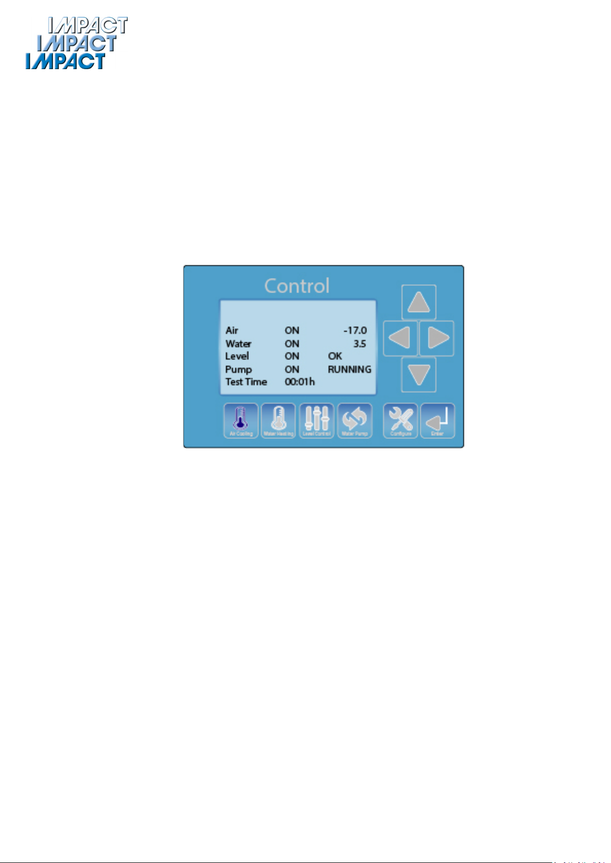
3.11 The air cooling and water heating can be controller independently and turned on or off as
required using buttons on the control system. As well as the main screen, there are LED indicators to
indicate if they are on and off. The value on the control screen shows the actual value. When you press
the Air Cooling Button, the onscreen timers starts to count up indicating the time the samples have been
under test conditions
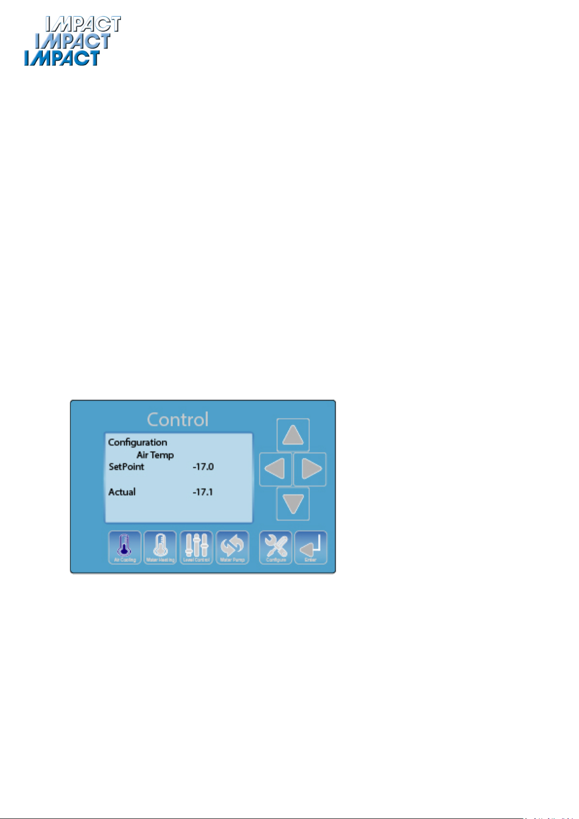
3.12 To change set points, and control parameters including calibrations, scroll through the menu
pages using the up and down icon. They are set as the following
1Main Run Page
2Configure Air Temp
3Configure Water Temp
4Set Defrost Time
5Calibrate Air and Water Temperatures
3.13 To change air temperature set point
Press Down button to this page
Hold the Config button down for 5 seconds


