11900 OCT 14
DBZH-102
DBZH-102
5A, 250VAC
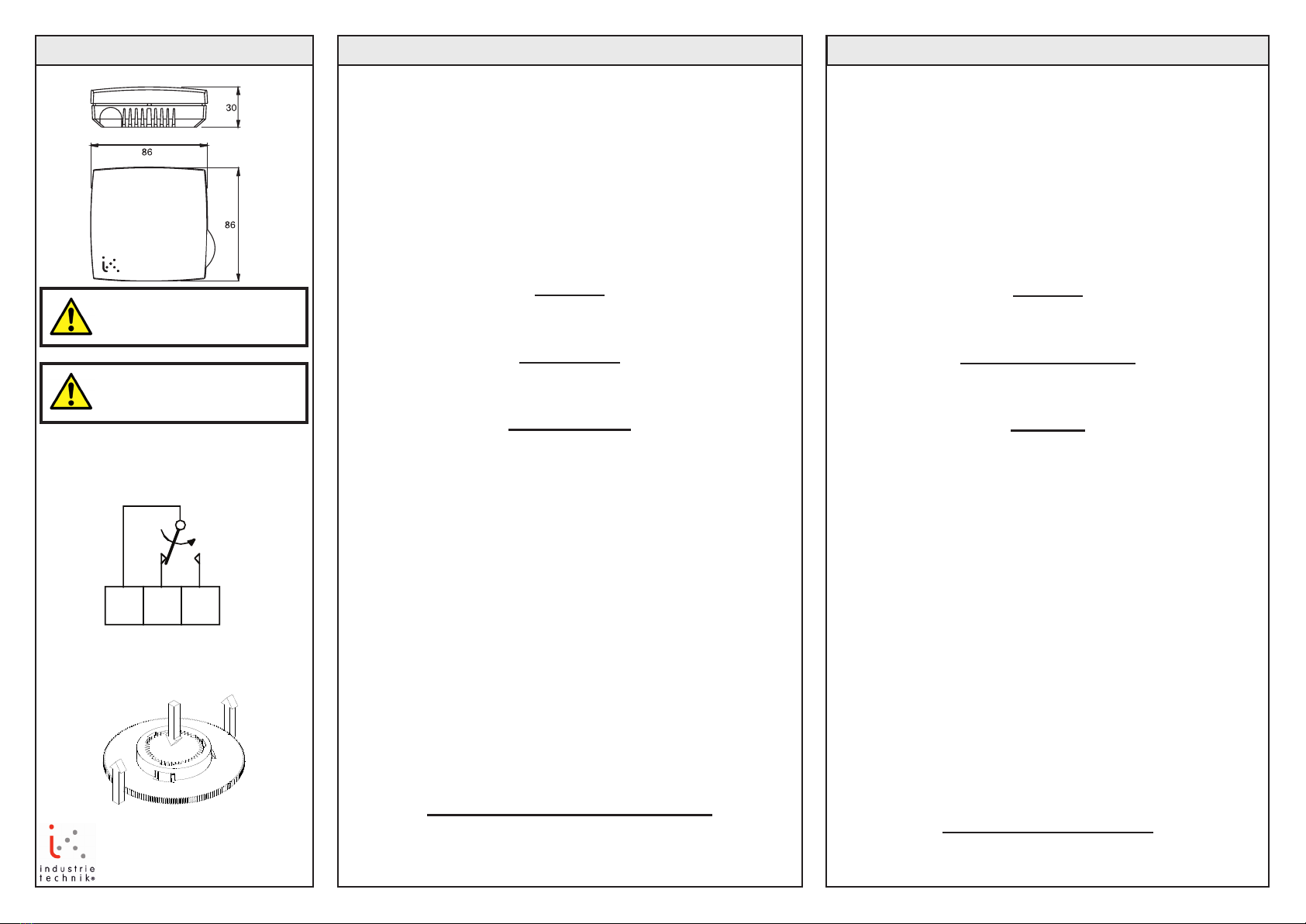
Fig 2
Fig 1
AB Industrietechnik Srl
Via Julius Durst, 70 - 39042 Bressanone (BZ) - Italy
Tel. +39 0472/830626 - Fax +39 0472/831840
IMPORTANTE: prima
dell’installazione e del cablaggio del
prodotto, leggere le presenti istruzioni.
ISTRUZIONI INSTRUCTION
Umidostato per ambiente
Installazione
Montare l’umidostato in un luogo caratterizzato da valori di tem-
peratura regolari e buona circolazione dell’aria. I fori di montaggio
presentano una distanza c:c di 60 mm che consente il montaggio su
scatola a parete. Cablaggio
Umidicazione 1+2
Deumidicazione 1+3
Manutenzione
Una volta completato il montaggio, eseguire la calibrazione
dell’umidostato. Successivamente la calibrazione dovrà essere ef-
fettuata ad intervalli regolari, ad esempio all’inizio di ogni stagione di
riscaldamento.
L’accumulo di polvere o altra sostanza su qualsiasi tipo di sensore,
a prescindere dal materiale con cui è realizzato (capelli, cotone o
plastica), compromette lo scambio igroscopico con l’aria circostante.
Pertanto è necessario rimuovere eventuali depositi ad intervalli
regolari servendosi di una spazzola morbida.
Calibrazione
1. Misurarel’umiditàrelativadell’ariainprossimitàdell’umidostato
utilizzando, ad esempio, uno psicometro o un altro strumento di
precisione.
2. Rimuovereilcoperchioanterioreeallentarelavitedibloccodel
setpoint.
3. Ruotarelamanopoladiregolazionedelsetpointnoadindivi-
duare il punto di commutazione.
Nel caso in cui sia necessario tarare il setpoint, il cerchio della
manopola di regolazione con scala graduata può essere rimosso
dal perno e rimontato in una posizione differente. Afferrare il
cerchio ed estrarlo contemporaneamente, esercitando una pres-
sione costante sul perno verso l’interno.
Vederegura2.
4. Rimontare la scala graduata con il livello misurato corretto in
posizione orizzontale in modo che sia visibile anche con il co-
perchio montato. Accertarsi che tutte le parti siano correttamente
serrate tra loro.
4. Impostare la manopola sul valore di controllo richiesto e, se
desiderato, bloccare la manopola utilizzando l’apposita vite.
LVD
Questo prodotto è conforme ai requisiti
dellaDirettivaeuropeasullabassatensione(LVD)IEC730-1eIEC730-2-9.
Room humidistat
Installation
Mount the humidistat in a location with an even temperature and
good air circulation.The mounting holes have a c:c distance of
60mminordertotonawallbox.
Wiring
Humidication 1+2
Dehumidication 1+3
Maintenance
Calibrate the humidistat after it has been mounted. Thereafter
itshouldbecalibratedatregularintervals,forexampleatthe
beginning of each heating season.
If dust or other matter is permitted to accumulate on any type
of sensing material (hair, cotton or plastic) its hygroscopic
interchange with the surrounding air is impaired. So remove all
deposits at regular intervals using a soft brush.
Calibration
1. Measuretherelativehumidityclosetothehumidistatusing
forexampleapsychrometerorotheraccurateinstrument.
2. Removethefrontandloosenthesetpointlockingscrew.
3. Twistthesetpointknobuntilyoundtheswitchingpoint.
Shouldthesetpointneedcalibrationtheknobrimwiththe
scale can be detatched from the hub and remounted in a
new position. Grip across the rim and pull out at the same
time as maintaining an inward pressure on the hub.
Seeg2.
4. Remount the scale with the correct measured value hori-
sontally to the right so that is is displayed even with the front
coverinplace.Makesurethepartssnaptogetherproperly.
4. Setthesetpointknobtothedesiredcontrolvalueand,ifdesi-
red,locktheknobusingthelockingscrew..
LVD
This product conforms with the requirements of
EuropeanLVDstandardsIEC730-1andIEC730-2-9.
IMPORTANT: Read these instruc-
tions before installation and wiring
of the product.