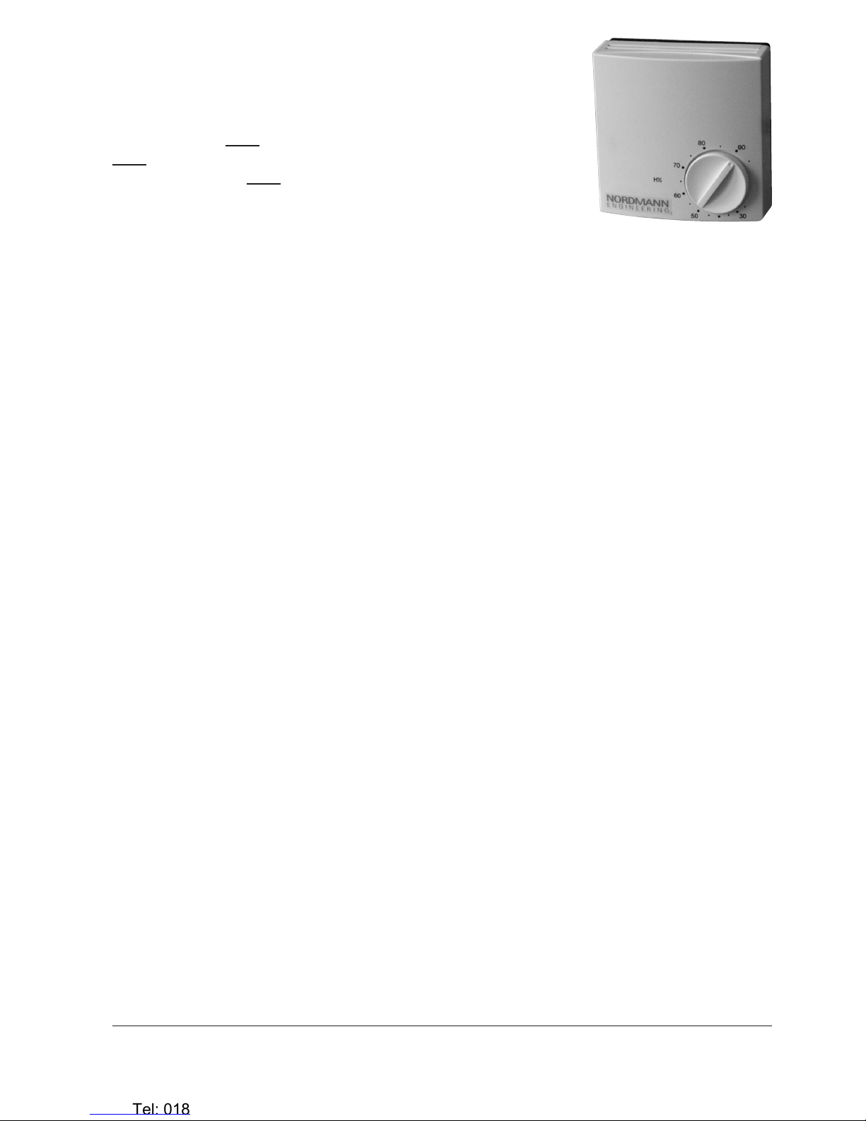
manuals.online logo
Brands
  1. Home
  2. •
  3. Brands
  4. •
  5. Nordmann
  6. •
  7. Humidistat
  8. •
  9. Nordmann HSN User manual

Nordmann HSN User manual

Raumhygrostat HSN
HSN room humidistat
Hygrostat ambiant HSN
Installationsanleitung
Installation Instructions
Instructions d’installation
2560658 DE/EN/FR 1112
Allgemein
Der Raumhygrostat HSN dient zur Ein/Aus-
Regelung des NordmannAT4, des Nordmann
RC4/DC4 und des Nordmann ES4. Diese In-
stallationsanleitung beschreibt denAnschluss
des Raumhygrostaten HSN an diese Geräte
sowie die Konguration der Geräte für den
Betrieb mit dem Raumhygrostat HSN.
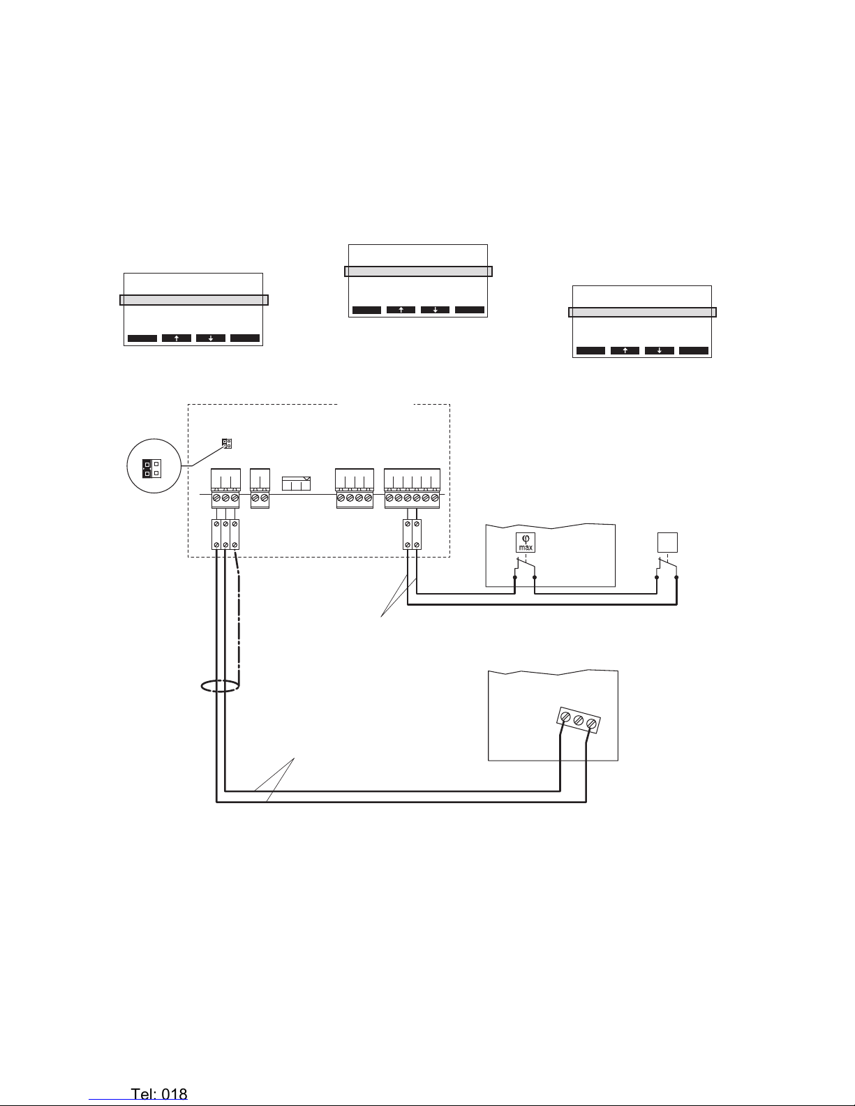
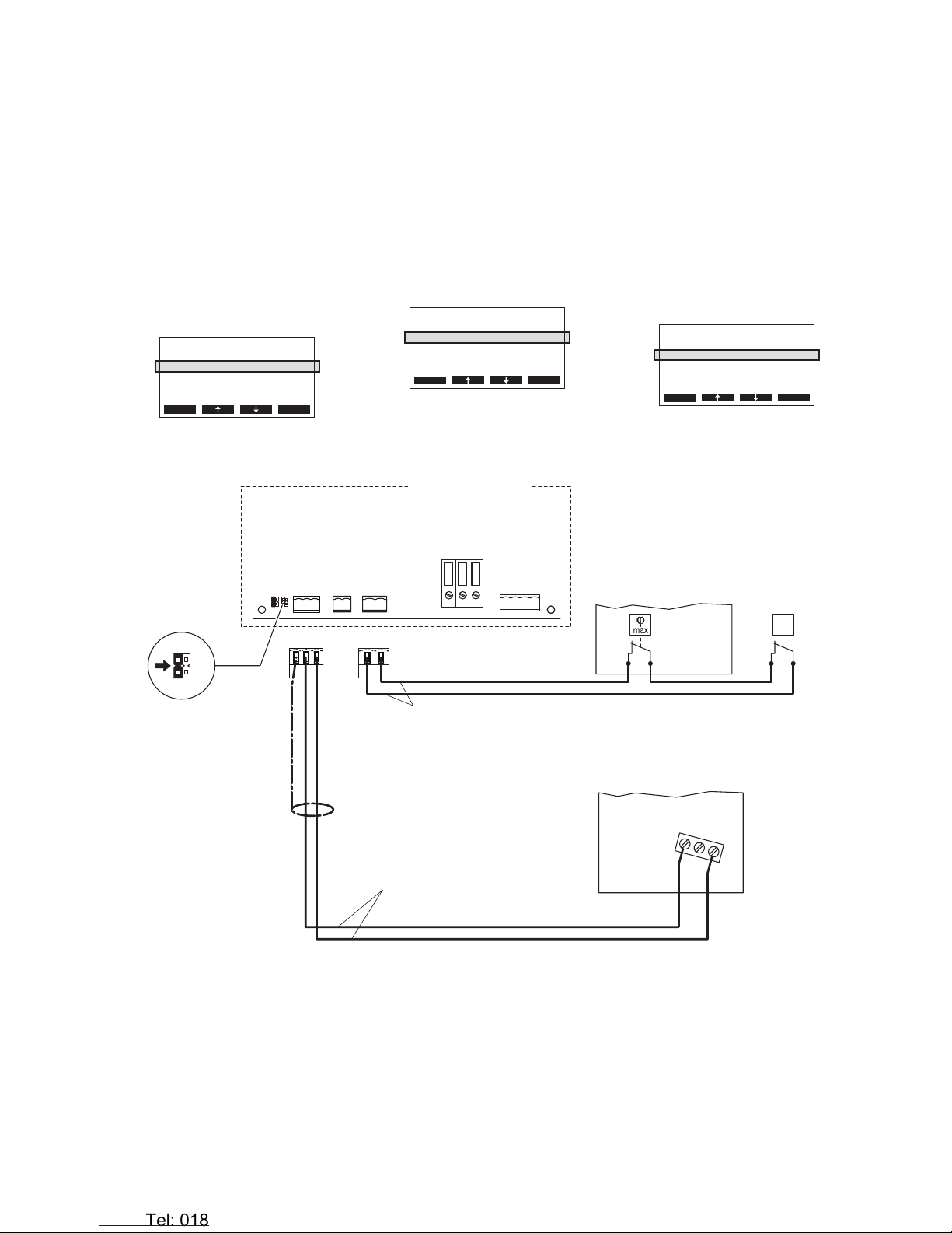
Hinweis: Zur Gewährleistung der Betriebs-
sicherheit ist der Betrieb der Befeuchter mit
einem Feuchtewächter (z.B. Kanalhygrostat
HBN oder Raumhygrostat HSN) und einem
Strömungswächter zu überwachen. Diese
Überwachungsgeräte sind an die externe
Sicherheitskette des jeweiligen Geräts anzu-
schliessen (Achtung! Die Kontakte müssen
potenzialfrei sein!).
DieseInstallationsanleitungisteineErgänzung
zurInstallationsanleitungzumRaumhygrostat
HSN und den Elektroinstallationsanleitungen
zudenentsprechenden Geräten.DieHinweise
in diesen Dokumenten müssen zwingend
beachtet und eingehalten werden.
Sicherheit
Beachten Sie bitte alle lokalen Vorschriften
betreffend die Ausführung von elek trischen
Installationen.
Die Installationsarbeiten dürfen nur durch
ausgewiesenes Fachpersonal (Elektriker
oder Fachkraft mit gleichwertiger Ausbil-
dung) durchgeführt werden.
Achtung Stromschlaggefahr! Vor Beginn
der Installationsarbeiten ist das Gerät, an
das der Raumhygrostat HSN angeschlossen
werden soll, vom Strom netz zu trennen. Der
Wiederanschluss an das Stromnetz darf erst
nach Fertigstellung sämtlicher Installations-
arbeiten erfolgen.
Achtung! Die elektronischen Bauteile im
Innerndes Raumhygrostaten HSN undder Be-
feuchter sind sehr empndlich gegen elektro
statische Entladungen. Zum Schutz dieser
Bauteile müssen für alle Installationsarbeiten
Massnahmen gegen Beschädigung durch
elektrostatische Entladung (ESD–Schutz)
getrof fen werden.
General
The HSN room humidistat is to be used for
On/Off regulation of the Nordmann AT4, des
Nordmann RC4/DC4 and the Nordmann ES4.
The current Installation Instructions describe
the connection of the HSN room humidistat
to these units as well as their conguration
required for operation with the HSN room
humidistat.
Note: For safety reasons the operation of the
humidiers must be monitored by a humidity
monitor (e.g. HBN duct humidistat or HSN
room humidistat) and a ow sensor. These
monitoring devices must be connected to
the external safety chain of the correspond-
ing unit (Caution! The contacts must be
potentialfree).
These Installation Instructions are a comple-
ment to the Installation Instructions of the HSN
room humidistat and the Electrical Installation
Instructions of the respective units. It is manda-
tory to observe and to follow the instructions
provided in these documents.
Safety
Please observe all local regulations concern-
ing the electric installation.
The installation work must be performed
only by adequately qualied personnel
(electrician or workman with equivalent
training).
Warning - danger of electric shock! Before
starting the installation work the unit to which
the HSN room humidistat will be connected
must be disconnected from the mains and
may be reconnected to mains only after all
installation work has been completed.
Warning! The electronic components inside
the HSN room humidistat and the humidiers
are very susceptible to electrostatic discharg-
es. For the protection of these components,
measures must be taken during all installation
work to prevent damage caused by electro-
static discharge (ESD–protection).
Généralités
L’hygrostat ambiant HSN est destinée pour
la régulation tout-ou-rien du Nordmann AT4,
des Nordmann RC4/DC4 et du Nordmann
ES4. Les présentes instructions d’installation
décrivent le raccorde ment de l’hygrostat am-
biant HSN à ces appareils et leur conguration
requise pour l’exploitation avec l’hygrostat
ambiant HSN.
Nota: pour des raisons de sécurité, l’opération
des humidicateurs doit être surveillée par un
contrôleur d’humidité (p.ex. l’hygrostat pour
gaine HBN ou l’hygrostat ambiant HSN) et
un contrôleur de ux d’air. Ces dispositifs
de surveillance doivent être raccordés à la
chaîne de sécurité externe de l’unité concer-
née (Attention! Les contacts doivent être
sans potentiel).
Les présentes instructions d’installation sont
un complément des instructions d’installa-
tion concernant l’hygrostat ambiant HSN et
des instructions d’installation électrique des
appareils respectifs. Les consignes gurant
dans ces documents sont à observer et à
respecter impérativement.
Sécurité
Veuillez observer chaque prescription lo-
cale concernent l’exécution d’installations
électriques.
Seules les personnes spécialisées compé-
tentes (électricien ou spécialiste de même
formation) sont autorisées à effectuer les
travaux d’installation.
Attention, risque de choc électrique! Avant
de commencer des travaux d’installation, sé-
parer du réseau électrique l’appareil destiné
à être raccordé à l’hygrostat ambiant HSN.
N’effec tuer le raccordement de l’humidicateur
au réseau électrique qu’au terme de tous les
travaux d’installation.
Attention! Les composants électroniques
intégrés dans l’hygrostat ambiant HSN et
les humidicateurs sont très sensibles aux
décharges électrostatiques. Ces composants
impliquent, lors de tous les travaux d’instal-
lation, la prise des mesures de précaution
contre leur détérioration par décharge élec-
trostatique.
NORDMANN
ENGINEERING
NORDMANN
ENGINEERING
Dampfluftbefeuchter econoVap
Heronhill - for all your Nordmann requirements
Tel: 01823 665660
www.heronhill.co.uk
Fax: 01823 665807
Anschluss des HSN am
Nordmann AT4
1. Den HSN über ein abgeschirmtes, zwei-
adriges Kabel (Aderquerschnitt maximal
0.5 mm2) gemäss dem untenstehenden
Schemaandieentsprechenden Klemmen
auf dem Leistungsprint des Gerätemoduls
A anschliessen.
2. Jumper “JP3” auf dem Leistungsprint des
Gerätemoduls A auf Position “24 V” ste-
cken.
3. Den Nordmann AT4 in Betrieb nehmen
und in der Einstellebene der Gerätesoft-
ware den Parameter “Regelung” auf
“24OnOff” einstellen(sieheMontage-und
Betriebsanleitung zum Nordmann AT4).
Connecting the HSN to the
Nordmann AT4
1. Use a shielded two-wire cable (maximum
wire section 0,5 mm2) to connect the HSN
to the appropriate terminals located on the
power board of unit module A (see wiring
diagram below).
2. Set the jumper “JP3” on the power board
of unit module A to position “24 V”.
3. SettheNordmannAT4intooperation, go to
the setup level of the software and set the
parameter “Hum.Control” to “24OnOff”
(refer to the Nordmann AT4 installation and
operating instructions).
Raccordement de l’HSN au
Nordmann AT4
1. Au moyen d’un câble blindé à deux brins
(secteur maximum de l’âme: 0.5 mm2),
brancher l’HSN selon le schéma électrique
ci-dessous aux bornes correspondantes
de la platine de puissance du module
d’appareil A.
2. A la platine de puissance du module
d’appareil A, encher le cavalier “JP3” sur
position “24 V”.
3. Mettre en service le Nordmann AT4,
accéder au plan de réglage du logiciel
et régler le paramètre “Rég.hygromèt”
sur “24OnOff” (voir les instructions
d’installation et d’exploitation concernant
le Nordmann AT4).
Regeleinst.
Regelung :24OnO
Sollwert :Set
Z-Begrenzung:Aus
SignalQuelle:Analog
Esc Set
Entr.Consig.
Rég.hygromèt:24VOnO
PointConsign:Set
An.Limiteur :Àl’arrêt
SourceSignal:Analog
Esc Set
Controls
Hum.Control :24VOnO
Hum.Setpoint:Set
Lim. Control:O
SignalSource:Analog
Esc Set
Nordmann AT4
Leistungsprint Module A
Power board Module A
Platine de puissance Module A
PEPESC2SC1NL1
X1
CONT. SIGN.
GNDINV+
X10
JP3
24V 5V
MAIN SUPPLYMODULE B
PEP1NP
X6
LIM. SIGN.
GNDIN EXT. SUP.
5V GND 24V
X11
X14
GND
IN
V+
SC2
SC1
XE2XE4
JP3
24V 5V
12
HBN
HSN
Sicherheitskette
Safety circuit
Chaîne de sécurité
min. Querschnitt pro Litze 1 mm2
min. cross section per wire 1 mm2
Section min. par fil 1 mm2
∆p
Strömungswächter
Air flow monitor
Contôleur flux d’air
200-240 V / 50...60 Hz
max. Querschnitt pro Litze 0.5 mm2
max. cross section per wire 0.5 mm2
Section max. par fil 0.5 mm2
HSC
12
3
Feuchtewächter
Humidity monitor
Contrôleur d'humidité
Heronhill - for all your Nordmann requirements
Tel: 01823 665660
www.heronhill.co.uk
Fax: 01823 665807
Anschluss des HSN
am Nordmann RC4/DC4
1. Den HSN über ein abgeschirmtes, zwei-
adriges Kabel (Aderquerschnitt maximal
0.5 mm2) gemäss dem untenstehenden
Schema an die entsprechenden Klem-
men auf dem Leistungsprint des Gerätes
anschliessen.
2. Auf dem Leistungsprint des Nordmann
RC4/DC4 einen Jumper auf JP2-24 V
stecken und den Jumper auf JP15V (falls
vorhanden) entfernen.
3. Den Nordmann RC4/DC4 in Betrieb
nehmen und in der Einstellebene der
Gerätesoftware den Parameter “Rege-
lung” auf “24OnOff” einstellen (siehe
Betriebsanleitung zum Nordmann RC4/
DC4).
Connecting the HSN
to the Nordmann RC4/DC4
1. Use a shielded two-wire cable (maximum
wire section 0,5 mm2) to connect the HSN
to the appropriate terminals located on the
power board of the unit (see wiring diagram
below).
2. On the power board of the Nordmann
RC4/DC4: set a Jumper on JP2-24V and
remove the Jumper on JP15V (if a jumper
is set).
3. Set the Nordmann RC4/DC4 into opera-
tion, go to the setup level of the software
and set the parameter “Hum.Control” to
“24OnOff” (refer to the Nordmann RC4/
DC4 operating instructions).
Raccordement de l’HSN
au Nordmann RC4/DC4
1. Au moyen d’un câble blindé à deux brins
(secteur maximum de l’âme: 0.5 mm2),
brancher l’HSN selon le schéma électrique
ci-dessous aux bornes correspondantes
de la platine de puissance de l’appareil.
2. A la paltine de puissance du Nordmann
RC4/DC4: installer un cavalier sur JP2-
24 V et enlever le cavalier de JP25V (si
présent).
3. Mettre en service le Nordmann RC4/DC4,
accéder au plan de réglage du logiciel
et régler le paramètre “Rég.hygromèt”
sur “24OnOff” (voir les instructions
d’exploitation concernant le Nordmann
RC4/DC4).
CONT.SIGN
V+
GNDCTRL
12
HBN
HSN
Sicherheitskette
Safety circuit
Chaîne de sécurité
min. Querschnitt pro Litze 1 mm2
min. cross section per wire 1 mm2
Section min. par fil 1 mm2
Feuchtewächter
Humidity monitor
Contrôleur d'humidité
∆p
Strömungswächter
Air flow monitor
Contôleur flux d’air
X1 X4 X6
CTRL V+
1 21 21 2 3
GND
BASIC
0-10V
On/Off
24V
5V
PRO
JP4
JP3
JP2
JP1
LIMGND SC1SC2
SAFETY
SC1SC2
24V
5V JP2
JP1
200-240 V / 50...60 Hz
Nordmann RC4/DC4
Leistungsprint
Power board
Platine de puissance
PWR
MAIN SUPPLY
X9
LN PE
X8
NL SW N SWL
max. Querschnitt pro Litze 0.5 mm2
max. cross section per wire 0.5 mm2
Section max. par fil 0.5 mm2
HSC
12
3
Regeleinst.
Regelung :24OnO
Sollwert :Set
Z-Begrenzung:Aus
SignalQuelle:Analog
Esc Set
Entr.Consig.
Rég.hygromèt:24VOnO
PointConsign:Set
An.Limiteur :Àl’arrêt
SourceSignal:Analog
Esc Set
Controls
Hum.Control :24VOnO
Hum.Setpoint:Set
Lim. Control:O
SignalSource:Analog
Esc Set
Heronhill - for all your Nordmann requirements
Tel: 01823 665660
www.heronhill.co.uk
Fax: 01823 665807
Anschluss des HSN am
Nordmann ES4
1. Den HSN über ein abgeschirmtes, zwei-
adriges Kabel (Aderquerschnitt maximal
0.5 mm2) gemäss dem untenstehenden
Schema an die entsprechenden Klem-
men auf dem Leistungsprint des Gerätes
anschliessen.
2. Auf dem Leistungsprint des Nordmann
ES4 einen Jumper auf JP1 stecken.
Connecting the HSN to the
Nordmann ES4
1. Use a shielded two-wire cable (maximum
wire section 0,5 mm2) to connect the HSN
to the appropriate terminals located on the
power board of the unit (see wiring diagram
below).
2. On the power board of the Nordmann ES4:
set a Jumper on JP1.
Raccordement de l’HSN au
Nordmann ES4
1. Au moyen d’un câble blindé à deux brins
(secteur maximum de l’âme: 0.5 mm2),
brancher l’HSN selon le schéma électrique
ci-dessous aux bornes correspondantes
de la platine de puissance de l’appareil.
2. A la paltine de puissance du Nordmann
ES4: installer un cavalier sur JP1.
CONT.SIGN
V+ IN GND
X2 X3
VD
MAIN SUPPLY
L1 NSC1SC2
X1
On/Off Mode
JP1
12
HBN
HSN
Sicherheitskette
Safety circuit
Chaîne de sécurité
min. Querschnitt pro Litze 1 mm2
min. cross section per wire 1 mm2
Section min. par fil 1 mm2
∆p
Strömungswächter
Air flow monitor
Contôleur flux d’air
200-240 V / 50...60 Hz
Nordmann ES4
Leistungsprint
Power board
Platine de puissance
max. Querschnitt pro Litze 0.5 mm2
max. cross section per wire 0.5 mm2
Section max. par fil 0.5 mm2
HSC
12
3
Feuchtewächter
Humidity monitor
Contrôleur d'humidité
Heronhill - for all your Nordmann requirements
Tel: 01823 665660
www.heronhill.co.uk
Fax: 01823 665807
© Nordmann Engineering Ltd., Printed in Switzerland
Technische Änderungen vorbehalten
Technical data subject to modification
Sous réserve de modifications techniques
Heronhill - for all your Nordmann requirements
Tel: 01823 665660
www.heronhill.co.uk
Fax: 01823 665807
NORDMANN
ENGINEERING
NORDMANN
ENGINEERING
Dampfluftbefeuchter econoVap
Reg.No. 40002-2
Manufacturer:
Nordmann Engineering Ltd.
Talstr. 35-37, P.O. Box, CH-8808 Pfäffikon (Switzerland)
Phone +41 55 416 66 06, Fax +41 55 416 62 46
www.nordmann-engineering.com, [email protected]
Heronhill - for all your Nordmann requirements
Tel: 01823 665660
www.heronhill.co.uk
Fax: 01823 665807

Popular Humidistat manuals by other brands

GeneralAire GFX3 installation manual

GeneralAire

GeneralAire GFX3 installation manual

Aprilaire 112 Maintenance Instruction

Aprilaire

Aprilaire 112 Maintenance Instruction

GeneralAire GFX3 Installation and operating instructions

GeneralAire

GeneralAire GFX3 Installation and operating instructions

System air HR1 Instruction

System air

System air HR1 Instruction

nor-tec 2548731 installation instructions

nor-tec

nor-tec 2548731 installation instructions

MS Electronics IP65H Product guide

MS Electronics

MS Electronics IP65H Product guide

manuals.online logo
manuals.online logoBrands
  • About & Mission
  • Contact us
  • Privacy Policy
  • Terms and Conditions

Copyright 2025 Manuals.Online. All Rights Reserved.