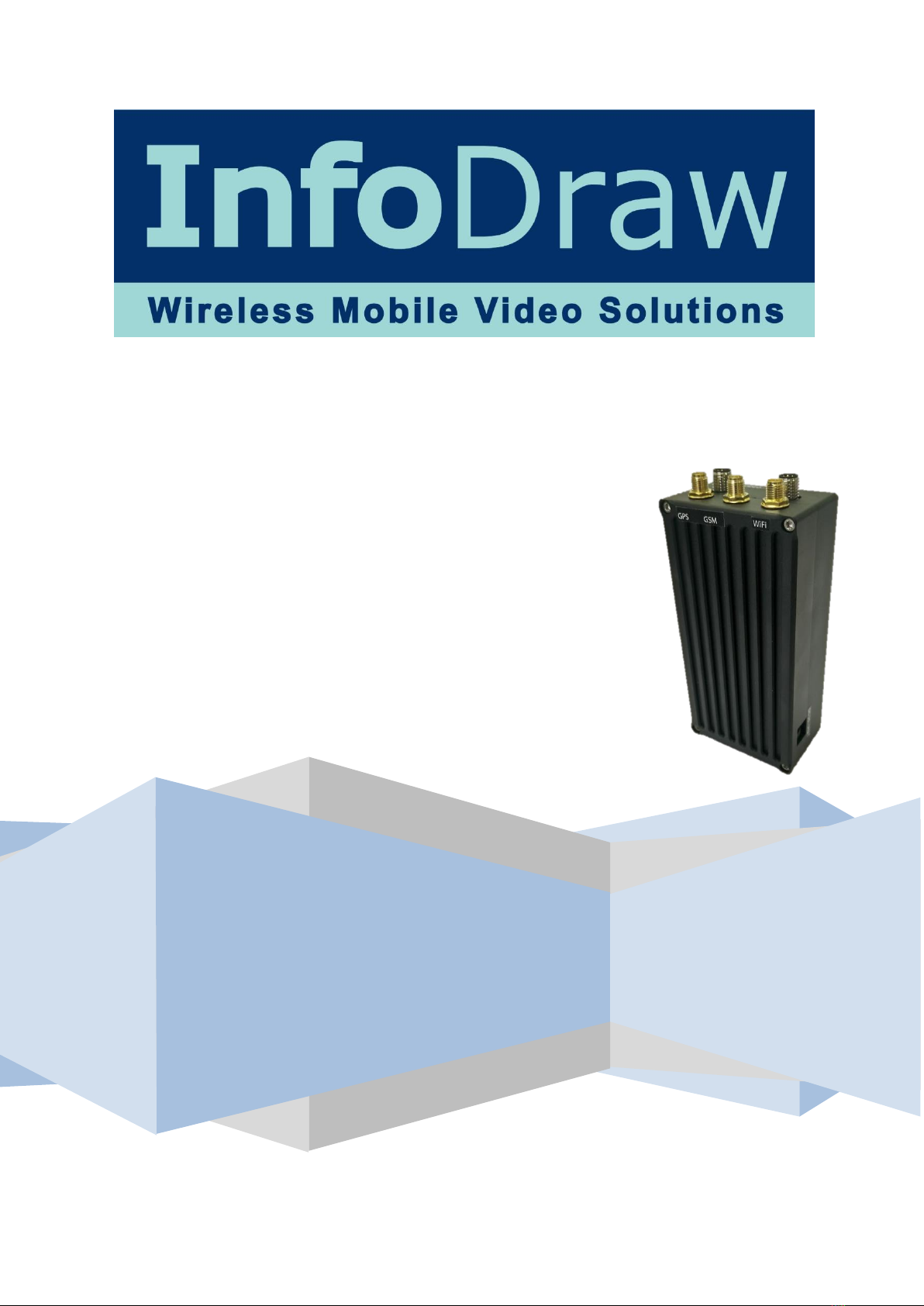
15 June, 2017 INFODRAW R&D PMRS-420 (v2.0) User Manual v6.2.0.0
3-3
M
RS
M
onitor
C
lient:........................................................................................................................36
Chapter 4 –MRS Software Components..........................................................................................................38
4-1
M
RS
M
onitor
C
lient
A
pplication: ................................................................................................38
4-1-1
S
etti n g L anguage:....................................................................................................................39
4-1-2
C
onnect i ng t h e
U
nit to t he
S
erve r: ...............................................................................40
4-1-3
V
i ewing
V
ideo ..........................................................................................................................42
4-1-4
O
ther
O
ptions..........................................................................................................................52
4-1-5
D
e v ic e L ocation:......................................................................................................................53
4-1-6 Audio...............................................................................................................................................66
4-1-7
R
ecording...................................................................................................................................71
4-1-8
V
M
D
: ..........................................................................................................................................95
4-1-9
G
P
I
O
(
S
en sors a n d
S
w it ches
)
: ..........................................................................................100
4-1-10
S
M
S
f
rom
D
evice:................................................................................................................103
4-1-11
P
hoto
S
napshots:..................................................................................................................106
4-1-12
S
ession:...................................................................................................................................107
4-1-13
N
eighbourhood: ...................................................................................................................108
4-3
M
RS
D
evice
C
onfigurator
A
pplication:.....................................................................................115
4-3-1
D
e v ic e Identif icati on.............................................................................................................116
4-3-2
C
onnect i on ..............................................................................................................................117
4-3-3
M
o dem...................................................................................................................................119
4-3-4 L o c a l
N
e twork ......................................................................................................................121
4-3-5
W
ireless L
A
N
...........................................................................................................................124
4-3-6
S
I
M
...........................................................................................................................................127
4-3-7
O
pen
V
P
N
...................................................................................................................................128
4-3-8
S
M
S
...........................................................................................................................................133
4-3-9
G
P
I
O
.........................................................................................................................................135
4-3-10
R
ecord i ng.............................................................................................................................139
4-3-11 L ocatio n.................................................................................................................................141
4-3-12
P
TZ
............................................................................................................................................142
4-3-13 L icens in g ...............................................................................................................................146
4-3-14
U
pgrade .................................................................................................................................150
4-3-15 Log .........................................................................................................................................152
4-3-16
M
R
S
C
onf ig ur at o r I n i t i al
S
etup.....................................................................................153
4-4 MRS Service Program:........................................................................................................................155
4-4-1 Administrator Menu: ...................................................................................................................157
4-4-2 Logging Menu: ..............................................................................................................................158