Infrico Pharma Care Series Dimensions and installation guide

Cabinets
Pharma Care Series
User Manual and Warranty

MAN-U-PER-PTRSD-EN Review: 01 28/03/2022

MAN-U-PER-PTRSD-EN Review: 01 28/03/2022
CONTENTS
1. INTRODUCTION............................................................................................................................................ 1
1.1 Intended use............................................................................................................................................ 2
2. SAFETY INSTRUCTIONS................................................................................................................................. 3
2.1 Symbols ........................................................................................................................................................... 3
3. LABELLING.................................................................................................................................................... 4
3.1 Technical label ......................................................................................................................................... 4
4RECEIPT AND INSPECTION............................................................................................................................ 5
5INSTALLATION .............................................................................................................................................. 5
5.1 Location ................................................................................................................................................... 5
5.2 Environmental operating conditions. ...................................................................................................... 6
5.3 Environmental conditions for transportation and storage...................................................................... 6
5.4 Unpacking ................................................................................................................................................ 6
5.5 Electrical connection................................................................................................................................ 6
5.6 Battery ..................................................................................................................................................... 7
5.7 Levelling................................................................................................................................................... 8
5.8 Rubber gasket.......................................................................................................................................... 9
5.9 Remote Alarm Installation....................................................................................................................... 9
5.10 Final Check-up ......................................................................................................................................... 9
5.11 Cleaning and Disinfection ........................................................................................................................ 9
6DRAWERS (OPTIONAL in PER07S, PER07G, PER15S, PER15G, PER36S and PER36G)................................. 11
6.1 Removing the Drawers ...........................................................................................................................11
6.2 Reinstalling the Drawers.........................................................................................................................11
6.3 Changing the position of the drawers ....................................................................................................11
7DIGITAL CONTROL ...................................................................................................................................... 13
7.1 Front panel .............................................................................................................................................13
7.2 The display screen ..................................................................................................................................13
7.3 Unlocking the keyboard..........................................................................................................................14
7.4 Changing the Set Point ...........................................................................................................................14
7.5 Manual defrost .......................................................................................................................................14
7.6 Changing parameters..............................................................................................................................14
7.7 Turning the equipment on and off .........................................................................................................15
7.8 Alarms.....................................................................................................................................................15
8TEMPERATURE MONITORING.................................................................................................................... 17
8.1 Set Point Control.....................................................................................................................................17
8.2 Product Simulation Temperature Probe (Optional) ...............................................................................17
9MAINTENANCE, CLEANING, AND CARE...................................................................................................... 18
9.1 Cleaning Procedure.................................................................................................................................18
9.2 Battery Replacement ..............................................................................................................................19
9.3 Spare Parts and Technical Support.........................................................................................................20
10 TROUBLESHOOTING................................................................................................................................... 21
11 USEFUL LIFE OF THE EQUIPMENT .............................................................................................................. 23
11.1 End of useful life .....................................................................................................................................23
12 TEMPERATURE CHART RECORDER (OPTIONAL)......................................................................................... 24
13 WARRANTY................................................................................................................................................. 25
13.1 Warranty certificate................................................................................................................................26

1
MAN-U-PER-PTRSD-EN Review: 01 28/03/2022
1. INTRODUCTION
Pharmaceutical refrigerators are designed to strictly meet the requirements necessary to operate in
pharmacies.
Pharmaceutical refrigerators are classified as CLASS I (Protection against electric shock) and a mode of
CONTINUOUS OPERATION according to UNE_EN_60601.
This product has been manufactured under strict quality controls and meets all the requirements
established by Infrico. Each unit has been tested and its quality is ensured before being shipped. This equipment
has been manufactured with recyclable materials, by means of an environmentally friendly production process.
MODELO
MODEL
Capacidad Bruta
(litros) Gross
Capacity (liters)
Medidas Exterior
(mm) Exterior
dimensions (mm)
Medidas Interior
(mm) Interior
dimensions (mm)
Claro de puerta
(mm) Door
opening (mm)
Nº Estantes
Shelves Number
Dimensiones
Estante (LxP)
Shelf size (LxD)
PER07S
58
445 x 526 x 818
358 x 312 x 523
358 x 516
2
315 x 248
PER07G
60
445 x 508 x 818
358 x 323 x 523
358 x 516
2
315 x 248
PER16S
141
600 x 688 x 824
505 x 451 x 617
505 x 552
3
458 x 398
PER16G
141
600 x 680 x 824
505 x 455 x 617
505 x 552
3
458 x 398
PER24S
236
600 x 688 x 1244
505 x 451 x 1037
505 x 972
4
458 x 398
PER24G
238
600 x 680 x 1244
505 x 455 x 1037
505 x 972
4
458 x 398
PER28S
327
600 x 688 x 1644
505 x 451 x 1437
505 x 1372
5
458 x 398
PER28G
330
600 x 680 x 1644
505 x 455 x 1437
505 x 1372
5
458 x 398
PER37S
373
600 x 688 x 1844
505 x 451 x 1637
505 x 1572
6
458 x 398
PER37G
376
600 x 680 x 1844
505 x 455 x 1637
505 x 1572
6
458 x 398
PTR30ISD
313
595 x 621 x 1876
483 x 426 x 1521
483 x 1311
7
418 x 398
PTR30IGD
328
595 x 621 x 1876
483 x 446 x 1521
483 x 1311
7
418 x 398
PTR40ISD
398
670 x 683 x 1963
568 x 484 x 1338
568 x 1280
7
500 x 443
PTR40IGD
413
670 x 683 x 1963
570 x 504 x 1338
568 x 1280
7
500 x 443
PTR65ISD
506
687 x 870 x 1955
534 x 633 x 1207
534 x 1350
7
452 x 585
PTR65IGD
521
687 x 870 x 1955
534 x 654 x 1207
534 x 1350
7
452 x 585
PTR80ISD
719
797 x 1000 x 1955
645 x 803 x 1388
645 x 1350
7
564 x 750
PTR80IGD
737
797 x 1000 x 1955
645 x 823 x 1388
645 x 1350
7
564 x 750
PTR130ISD
1166
1385 x 834 x 1955
1234 x 681 x 1388
534 x 1350
14
452 x 585
PTR130IGD
1202
1385 x 834 x 1955
1234 x 702 x 1388
534 x 1350
14
452 x 585
Temperature range of the equipment: 2 ºC to 8 ºC (35,6ºF a 46,4ºF)
Accuracy: ± 0.1 ºC (±0,2ºF)
Display error values: ±0.2 ºC (±0,4ºF)

2
MAN-U-PER-PTRSD-EN Review: 01 28/03/2022
Please read this manual carefully before installing your new device to become familiar with all of its
advantages.
OBLIGATION! This device must be used only for the purpose described in this manual.
1.1 Intended use
Our equipment is designed for the storage and preservation of pharmaceutical products at a
temperature range of 2 ºC to 8 ºC. (35,6ºF a 46,4ºF)

3
MAN-U-PER-PTRSD-EN Review: 01 28/03/2022
2. SAFETY INSTRUCTIONS
In this manual and on the labels of this product, the terms Warning and Caution convey the following
meaning:
•Warning: A potentially hazardous situation which, if not avoided, could result in serious injury or death.
•Caution: A potentially hazardous situation which, if not avoided, may result in minor or moderate injury or
damage to equipment.
Please read this manual and the product labels carefully before installing or using this product. Failure
to follow these instructions may cause the product to malfunction, which may result in injury or damage.
The use of electrical devices implies the implementation of basic safety instructions such as:
•Follow the recommendations in this manual to properly locate and place this device prior to installation.
•Do not allow children to handle the device, as they could damage it, or themselves, seriously.
•Do not touch the cold surfaces of the freezing devices, as such surfaces may adhere to skin.
•Do not store or use flammable products near the device.
•Unplug the device before any cleaning, repair or maintenance operation.
WARNING!: Any manipulation of the device must be carried out by an authorised technical support
service provider.
WARNING!: 'No modification is permitted on this equipment.'
WARNING!: We inform you that the person installing the device is responsible for carrying out the
installation as instructed in the user manual.
WARNING!: We remind you that you are responsible for the proper maintenance of the equipment.
The manufacturer is not to be held liable for issues resulting from improper maintenance.
2.1 Symbols
WARNINGS
OBLIGATION

4
MAN-U-PER-PTRSD-EN Review: 01 28/03/2022
PROHIBITION
BATTERY
GROUNDING
3. LABELLING
In our equipment, labels are attached to the inside of the products. Their exact location is the top inner
left side.
3.1 Technical label

5
MAN-U-PER-PTRSD-EN Review: 01 28/03/2022
4RECEIPT AND INSPECTION
•All Infrico products are factory tested to assess their quality and performance and are shipped free of defects.
•When you receive your device, it should be carefully examined for any damage that may have incurred during
transportation.
•If any damage is detected on the unit, you must retain all packaging material and report such damage on the
carrier's bill of lading. A claim must be immediately made to the transport company.
•If the damage is found during or immediately after installation, contact your distributor immediately.
WARNING!: Infrico is not to be held liable for any damage caused during transport.
5INSTALLATION
5.1 Location
This device is intended for indoor use only.
Be sure the location chosen for your unit must be able to provide good air circulation efficient
refrigeration.
Avoid locations near heat sources, such as sunny windows, ovens, heaters, as well as direct solar
radiation where temperatures can reach extreme values. In addition, do not choose a location in areas where
temperatures drop below 12 °C or rise above 32 °C.
You should allow enough clearance between the equipment and the side walls so that the 120° door-
opening lock can be used. Doors require a minimum angle of 90° to open properly, in order to use the maximum
door width available.
The surface of the final location where the device is to be placed must be strong enough to support the
total weight of the device considering its full maximum load capacity. In addition, it must be levelled and free of
vibrations. Reinforce the flooring if necessary.
WARNING!: Do not place the equipment so that it is difficult to operate on the disconnecting device
(power cord peg).
6
MAN-U-PER-PTRSD-EN Review: 01 28/03/2022
5.2 Environmental operating conditions.
Laboratory refrigerators are designed to be safe under the following conditions.
•Indoor use
•Altitude up to 2000 m (795 mbar)
•Temperatures from 12 ºC to 32 ºC (53,6ºF to 89,6ºF)
•Maximum Relative Humidity: 65 %
•Voltage fluctuations in mains of up to ±10 % of the nominal voltage.
5.3 Environmental conditions for transportation and storage.
Laboratory refrigerators are designed to be safe under the following transportation conditions.
•Storage temperature: from -15 ºC (5ºF) to 55 ºC (131ºF)
•Relative humidity: 20 - 85 % (non-condensing)
5.4 Unpacking
The devices are shipped from the factory on a wooden pallet and are packed in sturdy
wooden/cardboard boxes. The box is screwed to the wooden base. The screws must be removed prior to
unpacking to avoid damage to the unit.
All packaging materials are environmentally friendly and should be reused or recycled. Actively
contribute to the protection of the environment by demanding recyclable packaging and environmentally
friendly disposal methods.
WARNING: Infrico does not recommend knocking the unit forward, sideways or backward. However,
if this occurs, you must ensure that the unit remains in an upright position for at least 24 hours
before connecting it, so that the compressor oil returns to the compressor.
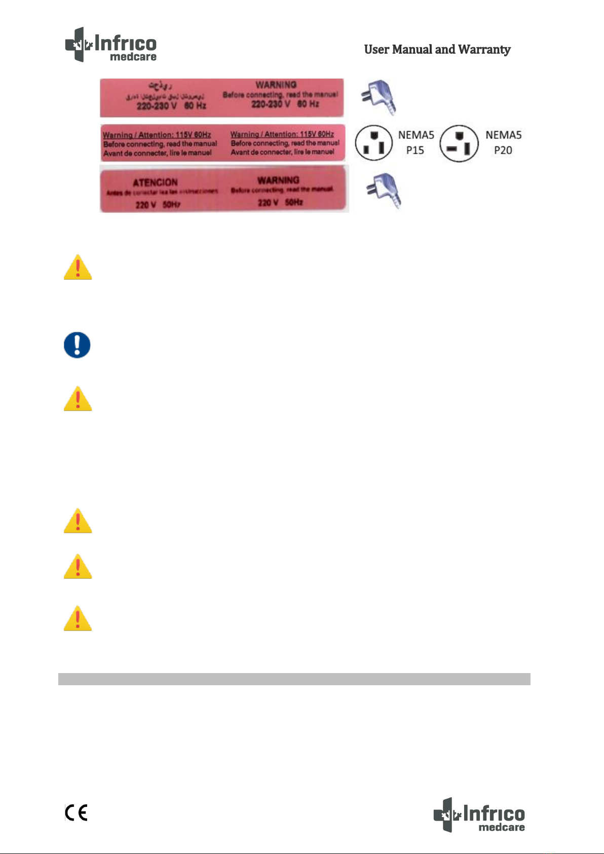
5.5 Electrical connection
WARNING!: Connect the equipment to a dedicated outlet with the correct voltage for the device.
Incorrect power or voltage fluctuations can cause serious damage to the equipment.
The equipment is prepared for power supply 220-230V 50 Hz, 220-230V 60 Hz, 115V, 60Hz. The
equipment has a hose and plug installed in the factory. Check the adhesive on the power cord. If you do
not have the proper outlet, you must install it beforehand. The means to isolate the equipment from
the power supply network is the plug of the power cable.
7
MAN-U-PER-PTRSD-EN Review: 01 28/03/2022
WARNING!: This unit must be grounded before use in order to ensure personal safety and the proper
operating of the equipment. A grounding fault may cause damage to personnel or equipment.
Always comply with the National Electrical Code. Do not connect the equipment to power lines that
are already overloaded.
OBLIGATION: The device must be connected to an exclusive dedicated circuit. Failure to comply with
this requirement shall void the warranty.
WARNING!: The device is designed to tackle a voltage fluctuation of around 10 % in relation to the
rated voltage indicated in the rating plate. A compressor fault due to higher fluctuations shall
automatically void the warranty.
Note: It is recommended to install a UPS (Uninterruptible Power Supply) or other system to avoid
voltage peaks or lack of electric current supply.
WARNING!: If the hose or the peg are altered in any way, they may constitute a serious hazard. Any
alteration of these components shall void the warranty.
WARNING: Devices connected to an extension cord are not covered by Infrico's warranty.
WARNING: The power cable can only be replaced by an authorized technical support service
provider.
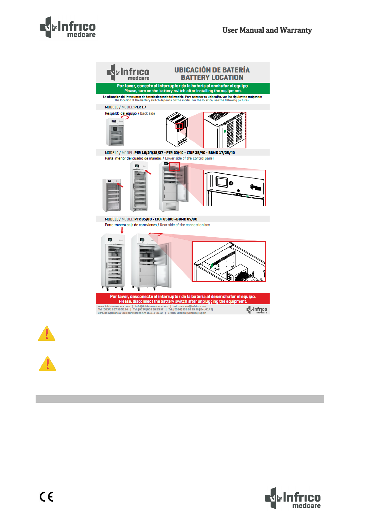
5.6 Battery
The equipment is equipped with a 12V-12Ah rechargeable lead-acid battery. (Except the models
PER07S/PER07G/LER07S/LER07G, which are with a 12V-7Ah rechargeable lead-acid battery).
Once the equipment has been installed, it must be connected by an approved installer. Follow the
instructions below.
8
MAN-U-PER-PTRSD-EN Review: 01 28/03/2022
WARNING!: Disconnect the battery switch after unplugging the equipment or in case of power failure
The warranty does not cover battery replacement due to discharge due to this circumstance.
WARNING!: For battery replacement see Section 9.2.
5.7 Levelling
It is very important that the device is perfectly levelled for proper operation, so that it drains properly,
the doors are aligned, and the unit is not subjected to undue stress.
These models are shipped from the factory with adjustable legs. In this case, adjust them until the unit
is completely stable and levelled.

9
MAN-U-PER-PTRSD-EN Review: 01 28/03/2022
Optionally, the units can be shipped with non-adjustable wheels for all models. In this case, you must
ensure that the floor where the unit will be located is levelled. The front wheel brakes must be locked for stable
operation.
5.8 Rubber gasket
To verify that the door is sealed, follow the steps below:
1. Opening the door.
2. Insert a strip of paper between the rubber gasket and the rubber gasket profile, and close the door.
3. Slowly remove the paper strip from the outside. While doing so, you should feel a little resistance.
4. Repeat this operation at 10 cm intervals covering the entire door frame. If the door does not close
properly, the gasket needs to be replaced or the door needs to be adjusted.
CAUTION! Hermetic door sealing is essential for blood bank refrigerators to function properly. Faulty
sealing allows humid air inside the device, which results in the accumulation of moisture in the
evaporator, resulting in poor temperature maintenance, increased operating time, and increased
operating costs.
5.9 Remote Alarm Installation
All models of pharmaceutical refrigerators have a remote alarm
connection that is located in the back of the equipment
5.10 Final Check-up
Before commissioning the device, follow the steps below:
1. Make sure the unit is free of all wood or cardboard packaging materials, both on the inside and
outside.
2. Verify the position of the stainless steel drawers. If you want to adjust the height of the drawers,
follow the instructions in section 6.3.
3. Verify that the unit is connected to a dedicated outlet.
5.11 Cleaning and Disinfection
Before commissioning the device, clean and disinfect it to remove any metal, plastic, sticker or residue
left.

10
MAN-U-PER-PTRSD-EN Review: 01 28/03/2022
Use water with a neutral detergent and dry properly.
CAUTION! Do not use a brush, acid, diluent, laundry soap, washing powder or boiling water to clean
the device.
These may damage the painted surface, as well as the stainless steel surface, or the plastic and
rubber components. Also, do not clean plastic and rubber components with a volatile material.

11
MAN-U-PER-PTRSD-EN Review: 01 28/03/2022
6DRAWERS (OPTIONAL in PER07S, PER07G, PER15S, PER15G, PER36S and PER36G)
6.1 Removing the Drawers
To remove the drawers, complete the following steps:
1. Pull the drawer towards you until the slide rails are fully extended.
2. Press on the back of the side clips to unlock the drawer lock.
3. Lift the front of the drawer and pull it back to remove it.
6.2 Reinstalling the Drawers
To reinstall the drawers, complete the following steps:
1. Insert the drawer in the side slide rails tilting it at about 45º. Once it is fit on the rails, place it in
a horizontal position.
2. Press on the front of the side clips to lock the drawer latch.
3. Insert the drawer all the way in.
6.3 Changing the position of the drawers
The drawer slide rails are height adjustable. You can place these rails in the vertical slits that are spaced
at intervals of 50.
To change the position of the drawer slide rails, complete the following steps:
1. Pull the front of the slide rail upwards until the front flap comes out of its place.
2. Then pull the slide rail forwards until the rear flap comes out of its place too.
3. Change the height as desired by following the steps in reverse to put the slide rail back in
place.

12
MAN-U-PER-PTRSD-EN Review: 01 28/03/2022
13
MAN-U-PER-PTRSD-EN Review: 01 28/03/2022
7DIGITAL CONTROL
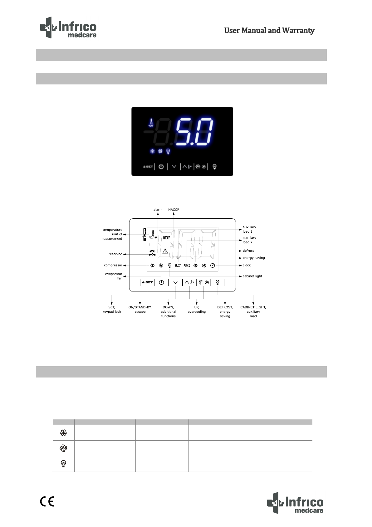
7.1 Front panel
7.2 The display screen
The following icons appear on the screen:
LED
ON
OFF
FLASHING
compressor ON
compressor OFF
- Compressor protection activated
- Setpoint setting
Evaporator fan ON
Evaporator fan OFF
Fan shutdown activated
Interior light ON
Interior light OFF
Interior light activated via digital input

14
MAN-U-PER-PTRSD-EN Review: 01 28/03/2022
AUX 1
Auxiliary function 1
ON
Auxiliary function 1
OFF
- Auxiliary function 1 via digital input
- Auxiliary function 1 via digital input
AUX 2
Auxiliary function 2
ON
Auxiliary function 2
OFF
- Auxiliary function 2 via digital input
- Auxiliary function 2 - delay activated
Defrost or pre-
dripping activated
-
- Defrost delay activated
- Dripping time enabled
- Energy saving
activated
- Low power activated
-
-
View time
-
date, time and day of the current week setting
View temperature
-
Fast refrigeration activated
HACCP
recording of HACCP
alarms
-
new HACCP alarm saved
Alarm activated
-
-
7.3 Unlocking the keyboard
Press any key for 1 second: The screen shows the unlocking message 'UnL'.
7.4 Changing the Set Point
Check that the keyboard is unlocked.
Press the SET key.
Press the up or down key to set a value within the r1 and r2
limits.
Press the Set key (or do not press for 15 s).
7.5 Manual defrost
Check that the keyboard is unlocked, and that quick refrigeration is not active.
Press the Defrost key for 2 s.
If P3 = 1 (by default), defrost is activated whenever the evaporator temperature is below limit d2.
7.6 Changing parameters

15
MAN-U-PER-PTRSD-EN Review: 01 28/03/2022
Press the SET key for 4 seconds: the screen will show the message
'PA'.
Press the SET key.
Press the up and down keys to enter the password (by default '-19').
Press the Set Key (or do not press for 15 s). The screen will display
the message 'SP'.
Press the up and down keys to select a parameter.
Press the SET key.
Press the up and down keys to select a value.
Press the Set key (or do not press for 15 s).
Press the SET button for 4 seconds (or do not press for 60 s) to end
the process.
7.7 Turning the equipment on and off
If POF = 1 (by default), press the ON/STAND-BY key for 2 seconds.
If the device is turned on, the screen will display the value P5 ('Temperature inside chamber'); if the screen
displays any alarm code, go to section 5.8 'Alarms'.
7.8 Alarms
CODE.
DESCRIPTION
RESTART
TO CORRECT
Pr1
Chamber probe alarm
automatic
- check P0
Pr2
Evaporator probe alarm
automatic
- check the status of the probe
Pr3
Auxiliary probe alarm
automatic
- check the electrical connection
rtc
Clock alarm
manual
Set date, time and day of the week
AL
Low temperature alarm
automatic
check A0, A1 and A2
AH
High temperature alarm
automatic
check A4 and A5
id
Door open alarm
automatic
check i0 and i1
PF
Power fault alarm
manual
- Press a key
- Check the electrical connection
COH
High condensation
warning
automatic
check C6
CSd
High condensation alarm
manual
- Turn the device off and on again
- check C7
iA
Multifunction input
alarm
automatic
check i5 and i6
iSd
High pressure alarm
manual
- Turn the device off and on again
- check i5, i6, i8, i9
LP
Low pressure alarm
automatic
check i5 and i6
C1t
Compressor thermal
switch alarm
automatic
check i5 and i6

16
MAN-U-PER-PTRSD-EN Review: 01 28/03/2022
C2t
Second compressor
thermal switch alarm
automatic
check i5 and i6
dFd
End defrost time alarm
manual
- Press a key
- check d2, d3 and d11
FUL
Full SD card alarm
manual
Free up space in the SD memory or replace the
card.
Sd
SD card missing alarm
manual
Insert SD card or replace it.
17
MAN-U-PER-PTRSD-EN Review: 01 28/03/2022
8.1 Set Point Control
Your unit has been factory set and tested to maintain a chamber temperature of -18°C. For most
laboratory applications, you will not need to change the temperature set point.
The chamber set point value is calculated according to the cut-off service parameters and a differential.
To adjust the set point:
1.- Access the service parameters as shown in section 7.6.
2.- Adjust the cut-off values and differential as necessary.
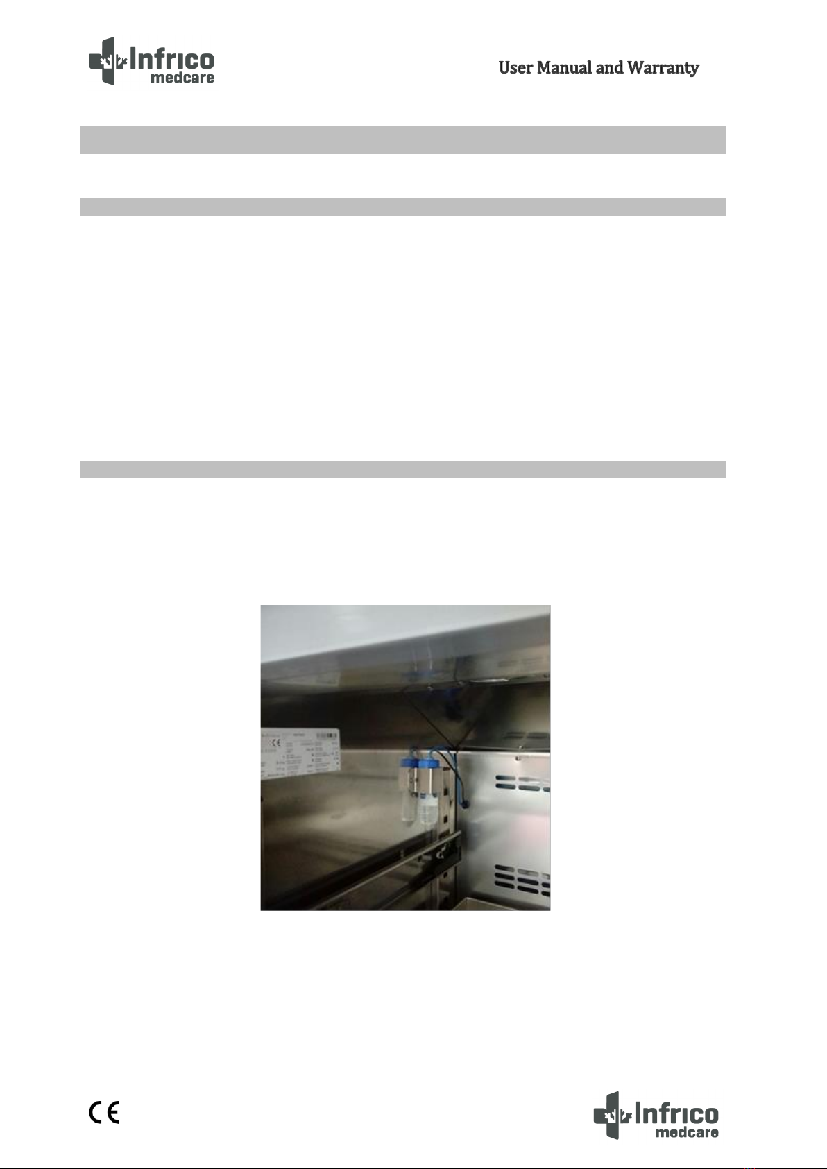
8.2 Product Simulation Temperature Probe (Optional)
The temperature of the chamber is measured by means of two probes inserted in a pot, placed on the side as
shown in the image. The pot contains 5% glycerine and 95% water to simulate samples of vaccines and /
or medications. Keep the sensor canister completely filled to the top.
8TEMPERATURE MONITORING
This manual suits for next models
20
Table of contents
Other Infrico Refrigerator manuals

Popular Refrigerator manuals by other brands

Frigidaire
Frigidaire FPHI2187KR - Professional Top Freezer parts catalog

VOX electronics
VOX electronics KS1430 operating instructions

Viking
Viking Designer DFBB363 Instruction

Amana
Amana AFI2538AEW Use & care guide

Zanussi
Zanussi ZBA22421SA user manual

Zanussi
Zanussi ZI 3165A - ZI 3243A Instructions for the use and care


