Innova Air Leaf 200 User manual

something new in the air
SL-SLI-SLSI-RS-SLS -RSI
DC Inverter
EN
Installation manual

2
Innova S.r.l
We want to thank you for choosing one of our products.
We are confident that you will be happy with your selection because it represents the state of the art
in the technology of home climate control.
By following the suggestions contained in this manual, the product you have purchased will operate
without problems giving you optimum room temperatures with minimum energy costs.
Conformity
This unit complies with European directives:
• Low voltage directive 2014/35/EU • Electro-magnetic compatibility 2014/30/EU;.
The following symbols provide the necessary information
for correct, safe use of the machine in a rapid, unmistakable
way
Symbols
U
User
- Refers to pages containing instructions or information
for the user.
I
Installer
- Refers to pages containing instructions or information
for the installer
S
Service
- Refers to pages containing instructions or information
for the installer TECHNICAL CUSTOMER SERVICE.
Editorial pictograms
Safety pictograms
Generic danger
- Signals that the operation described could cause
physical injury if not performed according to the safety
rules.
Danger of high voltage
- Signals that the operation described could cause
electrocution if not performed according to the safety
rules.
Danger due to heat
- Signals that the operation described could cause burns
if not performed according to the safety rules.
Do Not
- Refers to actions that absolutely must not be
performed.

3
1 4
2 4
3 5
4 5
5 6
1 8
2 8
3 8
4 9
5 9
6 10
7 10
8 11
9 12
10 13
11 13
12 13
13 14
14 14
15 14
16 15
17 17
1 18
2 18
3 19
EN
General
General warnings ...............................................................
Fundamental safety rules .........................................................
Product range .................................................................
Nominal technical features ........................................................
Overall dimensions Air Leaf ........................................................
Installation
Positioning the unit ..............................................................
Installation modes...............................................................
Minimum installation space ........................................................
Side opening ..................................................................
Vertical floor or wall installation......................................................
Horizontal or ceiling installation (SL,SLI) ...............................................
Mounting front grill safety support (SL) ................................................
Air intake grill fixing (SL, SLS, RS) ...................................................
Hydraulic connections ...........................................................
Condensation discharge..........................................................
Filling the system ...............................................................
Evacuating air while filling the system.................................................
Electrical connections ............................................................
Maintenance ..................................................................
Cleaning the outside.............................................................
Cleaning air suction filter ..........................................................
Energy saving tips ..............................................................
Troubleshooting
Troubleshooting ................................................................
Table of anomalies and remedies ...................................................
Technical specifications ..........................................................

4
1.1
1.2
General warnings
Fundamental safety rules
After unpacking, make sure that all the components are
present. If not, contact the INNOVA agent who sold the
appliance to you.
INNOVA appliances must be installed by an authorised
installer who, on completion of the work, will release a
declaration of conformity to the client in respect of the
laws in force and the indications given by INNOVA in the
instructions leaflet supplied together with the appliance.
These appliances have been designed both for
conditioning and/or heating environments and must
be destined for this use only and compatibly with their
performance characteristics.
INNOVA accepts no responsibility, either contractual or
extra-contractual, for any damage caused to persons,
animals of property as a result of incorrect installation,
adjustment or maintenance or improper use.
In case of water leaks, turn the master switch of the
system to "OFF" and close the water taps.
As soon as possible, call the INNOVA technical service
department or else professionally qualified personnel
and do not intervene personally on the appliance.
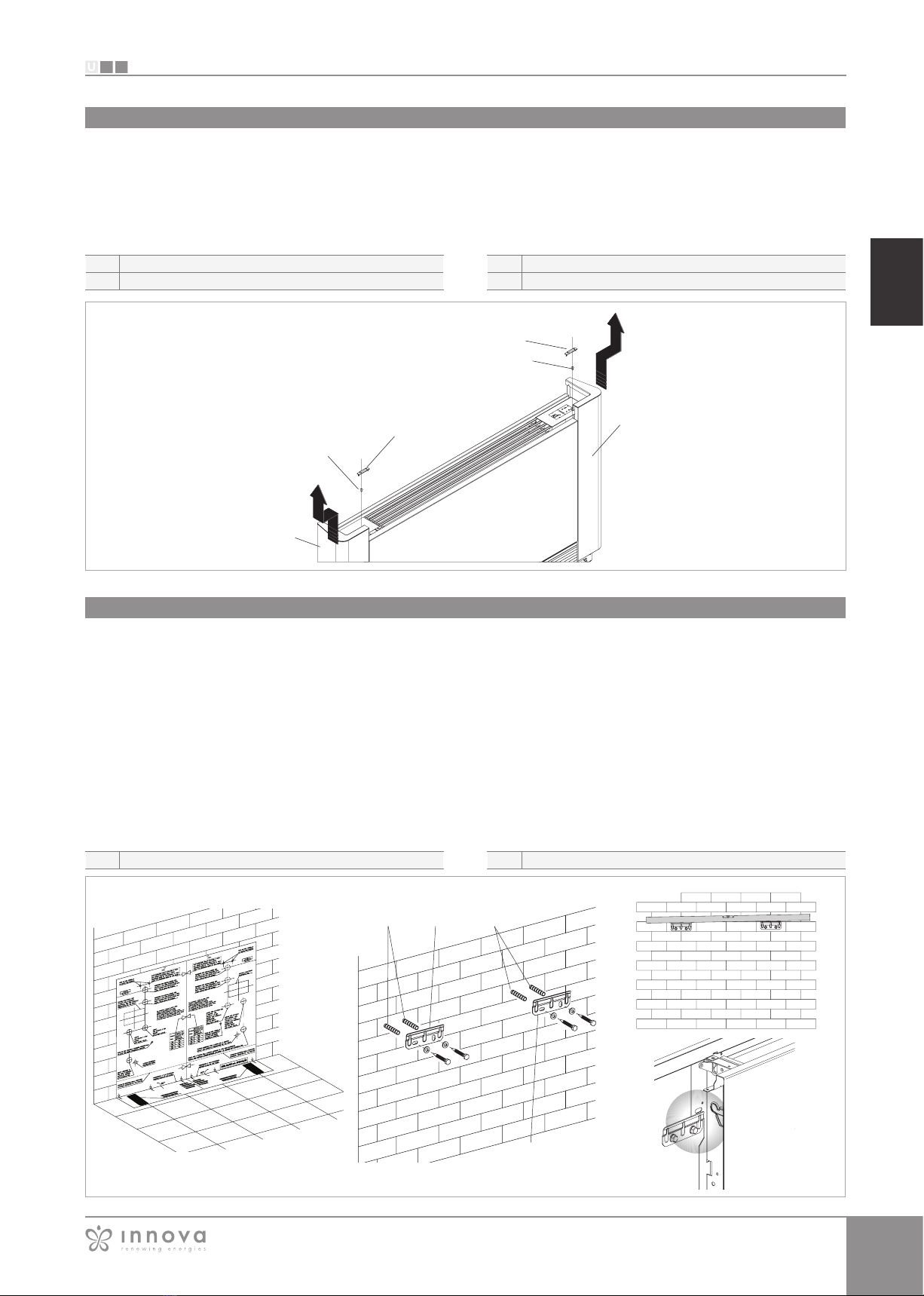
The imbedded Air Leaf SLI, RSI and SLSI series do not
have a grill or covering plate. Provide safety guards and
air inlet/outlet grills to prevent accidental contact with the
device.
If the appliance is not used for a log period of time, the
following operations should be performed:
- Turn the master switch of the system to "OFF"
- Close the water taps
- If there is the risk of freezing, make sure that anti-freeze
has been added to the system otherwise empty the
system.
If the room temperature is too low ot too high it is
damaging for the health and is also a useless waste of
energy.
Avoid prolonged contact with the direct air flow.
Do not leave the room closed for long periods.
Periodically open the windows to ensure a correct
change of air.
This instruction leaflet is an integral part of the
appliance and consequently must be kept carefully
and must ALWAYS accompany the appliance, even
when it is passed to a new owner or user or transferred
onto another system. If it is lost or damaged, please
contact the local INNOVA technical service centre.
All repair or maintenance interventions must be
performed by the technical service department or by
professionally qualified personnel as foreseen in this
booklet. Do not modify or intervene on the appliance
as this could create dangerous situations and the
manufacturer will not be responsible for any damage
caused.
Danger from burns - take care when touching
Remember that some fundamental safety rules should
be followed when using a product that uses electricity
and water, such as:
It is forbidden for the appliance to be used by children
or unassisted disabled persons.
It is forbidden to touch the appliance with wet hands
or body when barefoot.
It is forbidden to carry out any cleaning before having
disconnected the appliance from the electricity mains
supply by turning the system master switch to "OFF".
It is forbidden to modify the safety or adjustment
devices or adjust without authorisation and indications
of the manufacturer.
It is forbidden to pull, cut or knot the electrical cables
coming out of the appliance, even if it is disconnected
from the mains supply.
It is forbidden to poke objects or anything else through
the inlet or outlet grills.
It is forbidden to open the doors which access the
internal parts of the appliance without first turning the
system master switch to "OFF".
GENERAL

5
S
I
U
1.3
1.4
Air Leaf 200 400 600 800 1000
L 0,24 0,4 0,57 0,73 0,9
L 0,47 0,8 1,13 1,46 1,8
bar 10 10 10 10 10
°C 80 80 80 80 80
°C 4 4 4 4 4
"
Eurokonus 3/4 Eurokonus 3/4 Eurokonus 3/4 Eurokonus 3/4 Eurokonus 3/4
V/ph/Hz 230/1/50 230/1/50 230/1/50 230/1/50 230/1/50
A 0,11 0,16 0,18 0,26 0,28
W 11,9 17.6 19,8 26,5 29,7
kg 9 12 15 18 21
kg 17 20 23 26 29
kg 17,3 20,4 23,4 26,4 29,4
kg 12 14 16 19 23
Air Leaf 200 400 600 800 1000
L 0,47 0,8 1,13 1,46 1,8
L 0,16 0,27 0,38 0,49 0,6
bar 10 10 10 10 10
°C 80 80 80 80 80
°C
4 4 4 4 4
"
Eurokonus 3/4 Eurokonus 3/4 Eurokonus 3/4 Eurokonus 3/4 Eurokonus 3/4
V/ph/Hz 230/1/50 230/1/50 230/1/50 230/1/50 230/1/50
A 0,11 0,16 0,18 0,26 0,28
W 11,9 17.6 19,8 26,5 29,7
kg 10 13 17 20 24
kg 18 21 25 28 32
EN
GENERAL
It is forbidden to dispose of or leave in the reach of
children the packaging materials which could become
a source of danger.
It is forbidden to climb onto the appliance or rest any
object on it.
The external parts of the appliance can reach
temperatures of more than 70°C.
Product range
The there are three types of Air Leaf cooler-radiators/cooler-
convectors, SL, SLI and RS, each of which is offered in five
sizes with different performances and dimensions.
SL
Cooler-convector with metal cabinet (suitable for horizontal
or vertical installations).
SLI
Embedded cooler-convector without panels (suitable for
horizontal or vertical installations).
SLS
Fan with metal furniture low height (only suitable for vertical
installations)
SLSI
Embedded cooler-convector without panels, low hight
(suitable only for vertical installations)
RS
Cooler-convector with metal cabinet and radiant effect
(suitable for vertical installations).
RSI
Embedded cooler-convector without panels and radiant
effect (suitable only for vertical installations).
NOTE
Also available are specific SL and SLI versions with 4 pipes
with additional heating battery.
4 pipes RS, RSI and SLS version are not available.
4 pipes
2 pipes
TECHNICAL DATA (DC)
Heat exchanger water contents SLS
Heat exchanger water contents SL/SLI/RS
Maximum working pressure
Maximum water inlet temperature
Minimum inlet water temperature
Hydraulic fixtures
Power supply
Maximum current absorbed
Maximum power absorbed
Weight SLI
Weight SL
Weight RS
Weight SLS
TECHNICAL DATA (DC)
Cooling battery water contents
Heating battery water contents
Maximum working pressure
Maximum water inlet temperature
Minimum inlet water temperature
Hydraulic fixtures
Power supply
Maximum current absorbed
Maximum power absorbed
Weight SLI
Weight SL
Nominal technical features

6
S
I
U
1.5
U.M.
SL/RS/SLS 200 SL/RS/SLS 400 SL/RS/SLS 600 SL/RS/SLS 800 SL/RS/SLS 1000
A mm 735 935 1135 1335 1535
U.M.
RSI/SLI/SLSI 200 RSI/SLI/SLSI 400 RSI/SLI/SLSI 600 RSI/SLI/SLSI 800 RSI/SLI/SLSI 1000
A mm 378 578 778 978 1178
A
659
579
A129
129
459
379
A
SL / RS
SLS
SLI
GENERAL
Overall dimensions Air Leaf
2 pipes
Dimensions
Dimensions

7
S
I
U
U.M. SL 200 SL 400 SL 600 SL 800 SL 1000
A mm 735 935 1135 1335 1535
U.M. SLI200 SLI400 SLI600 SLI800 SLI1000
A mm 525 725 925 1125 1325
A126
636
SL 4T
SLI 4T
719
639
A129
A
SLSI
U.M.
RSI/SLI/SLSI 200 RSI/SLI/SLSI 400 RSI/SLI/SLSI 600 RSI/SLI/SLSI 800 RSI/SLI/SLSI 1000
A mm 378 578 778 978 1178
EN
GENERAL
4 pipes
Dimensions
Dimensions
Dimensions

8
S
I
U
2.1
2.2
2.3
INSTALLATION
INSTALLATION
Positioning the unit
Installation modes
Avoid installing the unit:
- in positions subject to exposure to direct sunlight;
- in proximity to sources of heat;
- in damp areas or places with probable contact with
water;
- in places with oil fumes
- in places subject to high frequency radio waves
Make sure that:
- the wall on which the unit is to be installed is strong
enough to support the weight;
- the part of the wall interested does not have pipes or
electric wires passing through;
- the interested wall is perfectly flat;
- there is an area free of obstacles which could interfere
with the inlet and outlet air flow;
- the installation wall is preferably an outside perimeter
wall to allow the discharge of the condensation outside;
- in case of ceiling installation (SL or SLI version) the airflow
is not directed towards persons.
The following descriptions of the various mounting phases
and the relative designs refer to a version of the machine
with fixtures on the left.
The operations for the mounting of machines with fixtures
on the right are exactly the same.
Only the images are to be considered as a mirror image.
To ensure that the installation is performed correctly and
that the appliance will perform perfectly carefully follow the
instructions indicated in this manual. Failure to respect the
rules indicated not only can cause malfunctions of the
appliance but will also invalidate the warranty and hence
INNOVA shall not respond for any damage to persons,
animals or property.
Minimum installation space
Figure indicates the minimum mounting distances
between the wall-mounted cooler-convector and furniture
present in the room.

9
S
I
U
2.4
2.5
B
AD
A
B
C
A
B
C
D
A B
A AB
B
EN
INSTALLATION
Side opening
Vertical floor or wall installation
- On the left-hand side lift the cover that protects the
screw, loosen the screw that fixes the left panel, then
move it slightly to the left and lift it up.
- On the opposite side, lift the cover that protects the
screw and unscrew it.
- Move the side panel slightly to the right and lift it out.
When mounting on the floor with support feet, refer to the
individual instructions leaflets supplied and the relative
manual for the mounting of the feet.
Using the paper template, trace the position of the two
fixing brackets on the wall. Use a suitable drill to make the
holes with and insert the wall plugs (2 for each bracket); fix
the two brackets. Do not over-tighten the screws so that
the brackets can be adjusted with a spirit level.
Fully tighten the four screws to block the two brackets.
Check the stability by manually moving the brackets to the
right and to the left, up and down.
Mount the unit, checking that it fits correctly onto the
brackets and checking that it is stable.
cover
fixing screws
left panel
right panel
wall plugs brackets

10
S
I
U
2.6
A A B
B
CD
A
B
C
D
A
B
C
2.7
A
A
B
C
INSTALLATION
Horizontal or ceiling installation (SL, SLI)
Using the paper template, trace on the ceiling the position
of the two fixing brackets and the two rear screws. Using
a suitable drill, make the holes and insert the wall plugs (2
for each bracket); fix the two brackets. Do not over-tighten
the screws. Position the machine on the two brackets,
keeping it in position and then fix the two screws into the
rear toggle bolts, one on each side.
Make sure that there is sufficient inclination of the unit
towards the drainage pipe to facilitate the water drainage.
Fully tighten all 6 fixing screws.
For installation of the SL versions, horizontal condensation
collection basin accessory kits are available GB0520/
GB0524.
The installation of RS, RSI, SLS units in horizontal position
is prohibited.
Carefully check the inclination of the exhaust pipe.
Any counterslope of the discharge line can cause
water leakage
wall plugs
brackets
screws
drainage pipe
Ties
Screws fixing springs
grid
Mounting front grill safety support (SL)
In the case in which the cooler-convector is installed in a
horizontal position, to guarantee the safety of the cleaning/
filter replacement operations it is obligatory that the two
clamps, in the supplied bag together with the instruction
manual and the accessories, are mounted by the installer.
Install braces to prevent the fall of the grid.
- Separate the two clamps;
- open the front grill and completely unscrew the fixing
screws on the springs;
- fix the two clamps, blocking them by retightening the
screws;
- fix the other part of the clamp to the grill using the
supplied screw;
- close the grill.

11
S
I
U
2.8
A
B
C
D
AB
C
EN
INSTALLATION
Air intake grill fixing (SL, SLS, RS)
drilled metal fin to be inserted in the guide
fixing screw
position for right insertion of metal fin
To prevent the grille from being accidentally removed or
left loosened by the quick-release pads preventing the fan
coil from functioning properly (in this case, the ventilation
stops and the grid safety alarm appears) 2 screws are
provided for fastening the grid.
The screws are TC 4,2x9,5 mm type.
So it it takes just fix the screws in dedicated holes located
on grill's fixing bars.
See the figure below.
FRONT
VIEW

12
S
I
U
2.9
U.M. 200 400 600 800 1000
mm 14 14 16 18 20
2.10
A
B
C
B
ø14mm
A
C
INSTALLATION
Hydraulic connections
The choice and sizing of the hydraulic lines must be made
by an expert who must operate according to the rules of
good technique and the laws in force, taking into account
that undersized pipes cause a malfunction.
To make the connections:
- position the hydraulic lines
- tighten the connections using the “spanner and
counter spanner” method
- check for any leaks of liquid
- coat the connections with insulating material.
The hydraulic lines and joints must be thermally insulated.
Avoid partially insulating the pipes.
Do not over-tighten to avoid damaging the insulation.
Use hemp and green paste to seal the threaded
connections; the use of Teflon is advised when there is
anti-freeze in the hydraulic circuit.
Pipeline diameter
Condensation discharge
The condensation discharge network must be suitably
sized (minimum inside pipe diameter 16 mm) and the
pipeline positioned so that it keeps a constant inclination,
never less than 1%. In the vertical installation, the discharge
pipe is connected directly to the discharge tray, positioned
at the bottom of the side shoulder underneath the hydraulic
fixtures. In a horizontal installation the discharge tube is
connected to the one already present on the machine.
For installation of the SL versions in a horizontal position,
horizontal condensation collection basin
accessory kits are available GB0520/GB0524.
- If possible, make the condensation liquid flow directly
in a gutter or a “rainwater” discharge.
- When discharging directly into the main drains, it is
advisable to make a siphon to prevent bad smells
returning up the pipe towards the room. The curve
of the siphon must be lower than the condensation
collection bowl.
- If the condensation needs to be discharged into a
container, it must be open to the atmosphere and
the tube must not be immerged in water to avoid
problems of adhesiveness and counter-pressure that
would interfere with the normal outflow.
- If there is a height difference that could interfere with
the outflow of the condensation, a pump must be
mounted:
- in a vertical installation mount the pump under the
lateral drainage tray;
- in a horizontal installation the pump position must be
decided according to the specific requirements.
Such pumps are commonly found in commerce.
However, on completion of the installation it is advisable
to check the correct outflow of the condensation liquid by
slowly pouring about ½ l of water into the collection tray in
about 5-10 minutes.
Connect to the condensation collection tray discharge
union a pipe for the outflow of the liquid blocking it
adequately. Check that the drip-collector extension is
present and correctly installed.
discharge fitting
tube for the outflow of the liquid
extension drip
Mounting the condensation discharge pipe in the vertical version

13
S
I
U
A B
AB
A
2.11
2.12
AA
ø14mm
EN
INSTALLATION
Mounting the condensation discharge pipe in the horizontal version (SL, SLI)
connection pipes discharge
To mount the horizontal bowl on the SL versions refer to
the instructions in kits GB0520/GB0524.
- check that the "L" pipe and the flexible rubber hose
are correctly connected to the bowl.
- slide in the side of the machine keeping the pipe in
position up against the front grill.
- fully close the side checking that the pipe remains
blocked in the special grove on the side.
N.B. for the horizontal installation carefully note the
following precautions:
- make sure that the machine is installed perfectly level
or with a slight inclination towards the condensation
discharge;
- insulate carefully the inflow and outflow pipes up to the
machine union to prevent any drops of condensation
outside the same collection bowl;
- insulate the bowl condensation discharge pipe along
all of its length.
Venting of the heat exchanger
Filling the system
Evacuating air while filling the system
When starting up the system, make sure that the hydraulic
unit lockshield is open. If there is no electric power and the
thermo-valve has already been powered use the special
cap to press the valve stopper to open it.
- Open all the shut off valves (manual or automatic);
- Start the filling by slowly opening the system water
filling tap;
- For the unit installed in a vertical position, take a
screwdriver and open the highest breather of the heat
exchanger; for appliances installed in a horizontal
position, open the highest positioned breather; for the
4-pipe versions act on the highest breathers on both
batteries.
- When water starts coming out of the breather valves
of the appliance, close them and continue filling until
reaching the nominal value for the system.
Check the hydraulic seal of the gaskets.
It is advisable to repeat these operations after the appliance
has been running for a few hours and periodically check
the pressure of the system.

14
S
I
U
A
B
C
2.13
2.15
2.14
C
A
B
INSTALLATION
Electrical connections
Make electrical connections according to the requirements
set out in sections General Warnings and Foundamental
Safety Rules by reference to the patterns present in the
installation and accessories manuals.
Before doing any work, make sure the power is switched
off.
The unit must be connected to the mains through a
multipolar switch with minimum contact opening of at
least 3mm or with a dewice that allows the complete
disconnection from the device under the overvoltage
conditions category III.
Maintenance
Cleaning the outside
Routine maintenance is indispensable to keep the Air Leaf
cooler-convector in perfect working condition, safe and
reliable over the years. This can be done every six months
for some interventions and annually for others, by the
Technical Service Assistance, technically authorised and
prepared, using always original spare parts.
Before every cleaning and maintenance intervention,
disconnect the appliance from the mains by switching
off the master switch.
Wait until the parts have cooled down to avoid the risk
of burns.
Do not use abrasive sponges or abrasive or corrosive
detergents to avoid damaging the painted surfaces.
When necessary, clean the outer surfaces of the Air Leaf
cooler-convector with a soft cloth damp cloth.
thermostatic head
valve
red plastic tool
Warnings for commissioning, mounting the thermostatic head
To mount the thermostatic head:
- tighten the head to the valve body
To facilitate the system mounting, filling and venting
operations, even without electric power, the thermostatic
head is supplied with a tool that keep it open.
Remove the tool from the thermostatic head before
starting the system.

15
S
I
U
2.16
A
B
C
D
AB
CD
A
B
C
D
B
A
D
C
EN
INSTALLATION
Cleaning air suction filter
- extract the front grill by lifting it slightly and turn it until it
comes right out of its seat;
- extract the filter, pulling it horizontally outwards.
Extraction of filter cells in the versions with aspiration grill with flaps
front grille
See grid
filter
extraction filter
After a period of continuous operation and in consideration
of the concentration of impurities in the air, or when he
intends to restart the system after a period of inactivity,
proceed as described.
- Insert your hands under the end of mobile panel
- Press the plastic lug
- Lift and extract the mobile panel
- Extract the filter
Extraction of filter cells in the versions with mobile aspiration panel
flap
Plastic tabs
filter
extraction filter

16
S
I
U
AB B C
A
B
C
A B
A
B
INSTALLATION
- suck up the dust with a vacuum cleaner
- wash the filter with running water without using
detergents or solvents, and leave to dry.
- Remount the filter on the cooler-convector (fig. 32 ref.
A), taking care to insert the lower flap
into its seat.
It is forbidden to use the unit without the net filters.
The appliance is fitted with a safety switch that
prevents the operation of the fan with the mobile panel
missing or out of position.
After finishing the cleaning of the filter, check that the
panel is mounted correctly.
Cleaning filtering seats
filter
lower edge
The filter housing
- For the versions with a grill with flaps, insert the two
lugs into the special slots, turn it and hook it up with a
slight tap on the upper part.
Ending Cleaning Operations
tabs slots

17
S
I
U
2.17
EN
INSTALLATION
Energy saving tips
- Always keep the filters clean;
- when far possible, keep the doors and windows
closed in the room being conditioned;
- limit where possible the effect of direct sun rays in the
rooms being conditioned (use curtains, shutters etc.)
- For the versions with a mobile panel, rest it in its
position, parallel to the front panel and press until it is
blocked.

18
S
I
U
3.1
3.2
INSTALLATION
TROUBLESHOOTING
Troubleshooting
Table of anomalies and remedies
In case of water leaks or anomalous functioning
immediately cut off the power supply and close the
water taps.
Should one of the following anomalies occur, contact
an authorised service centre or an authorised qualified
person, but do not intervene personally.
- The ventilation does not activate even if there is hot or
cold water in the hydraulic circuit.
- The appliance leaks water during the heating function.
- The appliance leaks water only during the cooling
function.
- The appliance makes an excessive noise.
- There are formations of dew on the front panel.
The interventions must be carried out by a qualified installer
or by a specialised service centre.
Effect Cause Remedy
A delayed activation of the ventilation
respect to the new temperature or
function settings.
The circuit valve needs some time to
open and as a result the hot or cold
water takes time to circulate in the
appliance.
Wait for 2 or 3 minutes to open the
circuit valve.
The appliance does not activate the
ventilation. No hot or cold water in the system. Check that the water boiler or cooler
are functioning correctly.
The ventilation does not activate even if
there is hot or cold water in the hydraulic
circuit.
The hydraulic valve remains closed.
Dismount the valve body and check if
the water circulation is restored.
Check the working efficiency of the
valve by powering it separately with
230V. If it activates the problem could
be the electronic control.
The fan motor is blocked or burnt out. Check the windings of the motor and
thefree rotation of the fan.
The micro-switch that stops the
ventilation when the filter grill is opened
does not close correctly.
Check that by closing the grill the micro-
switch contact is activated.
The electrical connections are not
correct. Check the electrical connections.
The appliance leaks water during the
heating function.
Leaks in the hydraulic connections of
the system.
Check the leak and fully tighten the
connections.
Leaks in the valve unit. Check the state of the gaskets.
There are formations of dew on the
front panel. Thermal insulation unstuck.
Check the correct positioning of the
thermo-acoustic insulation paying
attention to that in the front above the
finned heat exchanger.
There are drops of water on the air
outlet grill.
In situations of high humidity (>60%)
condensation could form, especially at
the minimum ventilation speeds.
As soon as the humidity starts falling
the phenomenon disappears. In any
case the presence of a few drops of
water in the appliance does not indicate
a malfunction.
The appliance leaks water only during
the cooling function.
The condensation bowl is blocked. Slowly pour a bottle of water in the
low part of the battery to check the
drainage; if necessary, clean the bowl
and/or increase the inclination of the
drainage pipe.
The condensation discharge does not
need an inclination for correct drainage.
The connection pipes and the valve unit
are not insulated well. Check the insulation of the pipes.

19
S
I
U
3.3
AIRLEAF - 2 TUBI
u.m.
200 400 600 800 1000
SL
RS SLI
RSI SLS
SLSI SL
RS SLI
RSI SLS
SLSI SL
RS SLI
RSI SLS
SLSI SL
RS SLI
RSI SLS
SLSI SL
RS SLI
RSI SLS
SLSI
(1) kW 0,91 0,51 2,12 1,21 2,81 1,62 3,30 2,12 3,71 2,60
(1) kW 0,73 0,43 1,72 1,01 2,11 1,44 2,71 1,99 2,90 2,34
(1) L/h 157 88 365 208 483 279 568 365 638 447
(1) kPa 12,1 4,1 8,2 11,2 17,1 5,1 18,0 5,3 21,2 7,2
(2) kW 1,02
0,61 2,21 1,51 3,02 2,03 3,81 2,62 4,32 3,11
(2) L/h
175 105 380 260 519 349 655 451 743 535
(2)kPa
9,1 5,2 9,2 16,1 19,1 7,3 21,2 8,1 23,3 10,2
L
0,47 0,28 0,80 0,50 1,13 0,61 1,46 0,77 1,80 0,90
bar
10 10 10 10 10 10 10 10 10 10
“ EK
3/4
(3) m³/h
146 113 294 228 438 331 567 440 663 489
m³/h
90 63 210 155 318 229 410 283 479 344
m³/h
49 35 118 84 180 124 247 138 262 167
Pa
10 10 10 10 13 10 13 10 13 10
V/ph/Hz
230/1/50
W
11,0 11,0 19,0 19,0 20,0 20,0 29,0 29,0 33,0 33,0
A
0,11 0,11 0,16 0,16 0,18 0,18 0,26 0,26 0,28 0,28
W
5,0 3,0 4,0 4,0 6,0 4,0 5,0 4,0 5,0 5,0
EN
INSTALLATION
Effect Cause Remedy
The appliance makes a strange noise.
The fan touches the structure. Check the clogging of filters and clean
them if necessary
The fan is unbalanced.
The unbalancing causes excessive
vibrations of the machine; replace the
fan.
Check the clogging of filters and clean
them if necessary Clean the filters
Technical specifications
Model u.m.
COOLING PERFORMANCES (W 7/12 °C; A 27 °C)
Total cooling capacity
Sensible cooling capacity
Water flow
Pressure drop
HEATING PERFORMANCES (W 45/40 °C; A 20 °C)
Heating capacity
Water flow
Pressure drop
HYDRAULIC DATA
Coil water content
Maximum operating pressure
Hydraulic connections
AERAULIC DATA
Air flow at the maximum
fan speed
Air flow at medium fan speed
Air flow at the minimum fan
speed
Static pressure available
ELECTRICAL DATA
Power supply
Electrical power absorption at
maximum fan speed
Maximum absorbed current
Electrical power absorption at
minimum fan speed

20
S
I
U
AIRLEAF - 2 TUBI
u.m.
200 400 600 800 1000
SL
RS SLI
RSI SLS
SLSI SL
RS SLI
RSI SLS
SLSI SL
RS SLI
RSI SLS
SLSI SL
RS SLI
RSI SLS
SLSI SL
RS SLI
RSI SLS
SLSI
dB(A)
51,00 51,00 53,00 53,00 54,00 54,00 55,00 55,00 57,00 57,00
(4) dB(A)
41,0 39,0 42,0 40,0 44,0 41,0 46,0 42,0 47,0 43,0
(4) dB(A)
33,0 33,0 34,0 33,0 34,0 34,0 35,0 34,0 38,0 36,0
(4) dB(A)
24,0 24,0 25,0 25,0 26,0 25,0 26,0 26,0 28,0 27,0
INSTALLATION
(1) Water temperature 7/12°C, Air temperature 27°C BS and 19°C BU, EN 1397
(2) Water temperature 40/45°C, Air temperature 20°C BS and 15°C BU, EN 1397
(3) Air flow measured with clean filters
(4) Sound pressure measured at a distance of 1 meter according to ISO7779
Model u.m.
SOUND DATA
Maximum sound power level
Sound pressure level at maxi-
mum air flow
Sound pressure level at me-
dium air flow
Sound pressure level at mini-
mum air flow
This manual suits for next models
36
Table of contents
Popular Freezer manuals by other brands

Brandt
Brandt UD2202 Instructions for installation and use

ITW
ITW Orbitalum ORBICOOL MW Translation of original operating instructions

TEKNIX
TEKNIX FFH1825WW instruction manual

Bertazzoni
Bertazzoni FRZ603UBNPTC user manual

Electrolux
Electrolux ERL-4796S Service manual

Coolzone
Coolzone CZ51059Z User instructions