Innovative Electronic Designs 4400 Series User manual

MODELS 4400 SERIES AND 4800 SERIES
AUTOMATIC MIXERS
GENERAL PROCEDURE
»BEFORE CONNECTING OR DISCONNECTING THE POWER SUPPLY REAR PANEL
CONNECTOR, ANY REAR PANEL WIRING, OR REMOVING OR REPLACING
JUMPERS (SHUNTS), PERFORM THE FOLLOWING STEPS:
1. DEPRESS THE FRONT PANEL POWER SWITCH TO THE OFF POSITION.
2. DISCONNECT THE POWER SUPPLY FROM THE AC POWER OUTLET.
FAILURE TO DO SO MAY RESULT IN DAMAGE TO THE EQUIPMENT AND WILL
VOID THE WARRANTY.
TOOLS REQUIRED
In order to perform all of the setup procedures and installation procedures described in
this document, the tools listed below will be required, but all are not required for each
procedure.
1. # 2 Phillips screwdriver (for removal of the top cover)
2. Small slotted screwdriver with insulated blade (supplied with mixer) for
installing/removing wiring or adjusting pots. GC 8608, or equivalent.
3. Small needle nosed pliers (for jumper removal and replacement)
JUMPERS
Jumpers, also referred to as shunts, are used extensively in the 4400 and 4800 Series
Automatic Mixers to select or set up alternatives or options. A jumper consists of a small
conductive clip encased in a molded plastic case. It is designed to slide onto two adja-
cent pins in a pin strip array. The pin strips used in this equipment have spacings of .100
inches. In the diagrams in this document, a jumper (shunt) is represented as a solid
black rectangle which covers two adjacent pins. The figure below illustrates several ex-
amples of jumpers.
Also used in this document is a reversed or negative representation of some compo-
nentstoaidinlocatingtheminthediagrams. Somereversedcomponentsarealsoillus-
trated in the figure below. Note particularly the difference between a reversed pin array
and a pin array with a jumper in place. Reversed components are used in the overall
views, only. Jumpers are shown only in the magnified views of the reversed compo-
nents.
4400 AND 4800 SERIES MIXERS MAY 1999 SECTION 4GROUP 20 SUB BPAGE 1
INSTALLATION INSTRUCTIONS MODELS 4400 SERIES AND 4800 SERIES AUTOMATIC MIXERS

MOUNTING AND VENTILATION
The 4400 and 4800 Series Automatic Mixers are designed for rack mounting in a stan-
dard EIA 19 inch equipment rack. When rack mounting these mixers, there are several
considerations which must be kept in mind.
Physically, each mixer requires one EIA rack space (1.75) inches. However, adequate
ventilation space must be provided for heat removal. For this reason, one empty EIA
rack space must be left between mixers. Do not cover the empty rack space with a solid
panel. Use a perforated or louvered vent panel.
Iftheyare not mounted in a rack,donot stack mixers directly on eachother. Spacethem
1.75inchesapart,allowingforthe freeflowofair betweenthem.Donot blockthelouvers
in the tops.
Rack mounting is usually accomplished with four 10-32 flat head machine screws and
cup washers. This prevents scratching of the front panel when appearance is important.
but it does not provide grounding. If grounding to the rack is required, it is recom-
mended that a grounding strap be added. If appearance is not critical, then the use of
fourroundheador pan head screws with lock washers,butnocup washers, will provide
grounding.
SECTION 4GROUP 20 SUB BPAGE 2MAY 1999 4400 AND 4800 SERIES MIXERS
MODELS 4400 SERIES AND 4800 SERIES AUTOMATIC MIXERS INSTALLATION INSTRUCTIONS
Innovative Electronic Designs, Inc. 9701 Taylorsville Road Louisville, Kentucky 40299 USA
Phone: (502) 267-7436 Fax: (502) 267-9070 Internet: http://www.iedaudio.com
hh
hh h
Figure1-Typical rack layout showing vent spaces

4400 AND 4800 SERIES MIXERS MAY 1999 SECTION 4GROUP 20 SUB BPAGE 3
INSTALLATION INSTRUCTIONS MODELS 4400 SERIES AND 4800 SERIES AUTOMATIC MIXERS
TABLE OF CONTENTS
General Procedure ...........................................1
Tools Required .............................................1
Jumpers .................................................1
Mounting and Ventilation ........................................2
Rear Terminal Connections, Inputs...................................4
Rear Terminal Connections, AC Power and Outputs .........................5
Remote Connector, Input and/or Main Output Option 1 and Auxiliary Input Option A ........6
Input and/or Main Output Option 2 and Logic Out...........................7
Remote Connector, Input and/or Main Output Option 1 Using 412PLC for Remote Level Control . 8
Combining Switch and Remote Output Level Control Using 412PLC ................9
Remote Connector, Force On/Force Off ...............................10
Overall View of Printed Circuit Board.................................11
Direct Output Level Controls .....................................12
Gain Adjustment of Gated Inputs ...................................13
Phantom Power Settings .......................................14
Enabling/Disabling Priority of Gated Inputs .............................15
Filibuster Limit Set of Gated Inputs ..................................16
Last Mic On and Onput for Gated Inputs ...............................17
Force On and Force Off for Gated Inputs...............................18
Digital Attenuator Defeat for Gated Inputs ..............................19
Discriminator Defeat for Gated Inputs ................................20
Discriminator Sensitivity of Gated Inputs...............................21
Release Time Adjustment of Gated Inputs ..............................22
Input Option Control Lines ......................................23
Auxiliary Mix Bus Sources.......................................24
Direct Output Source Selection ....................................25
Auxiliary Input Routing ........................................26
High Pass Filter Enable/Disable....................................27
Gated Off Attenuation of Gated Inputs ................................28
Auxiliary Output Level Controls ....................................29
Output Option Control Lines .....................................30
Phantom Power Option Voltage Selection ..............................31
Fuse Replacement ...........................................32

SECTION 4GROUP 20 SUB BPAGE 4MAY 1999 4400 AND 4800 SERIES MIXERS
MODELS 4400 SERIES AND 4800 SERIES AUTOMATIC MIXERS INSTALLATION INSTRUCTIONS
Innovative Electronic Designs, Inc. 9701 Taylorsville Road Louisville, Kentucky 40299 USA
Phone: (502) 267-7436 Fax: (502) 267-9070 Internet: http://www.iedaudio.com
hh
hh h
Figure 2 - Rear terminal connections
Inputs
REAR TERMINAL CONNECTIONS, INPUTS

4400 AND 4800 SERIES MIXERS MAY 1999 SECTION 4GROUP 20 SUB BPAGE 5
INSTALLATION INSTRUCTIONS MODELS 4400 SERIES AND 4800 SERIES AUTOMATIC MIXERS
Figure 3 - Rear terminal connections
AC power and outputs
REAR TERMINAL CONNECTIONS, AC POWER AND OUTPUTS
SECTION 4GROUP 20 SUB BPAGE 6MAY 1999 4400 AND 4800 SERIES MIXERS
MODELS 4400 SERIES AND 4800 SERIES AUTOMATIC MIXERS INSTALLATION INSTRUCTIONS
Innovative Electronic Designs, Inc. 9701 Taylorsville Road Louisville, Kentucky 40299 USA
Phone: (502) 267-7436 Fax: (502) 267-9070 Internet: http://www.iedaudio.com
hh
hh h
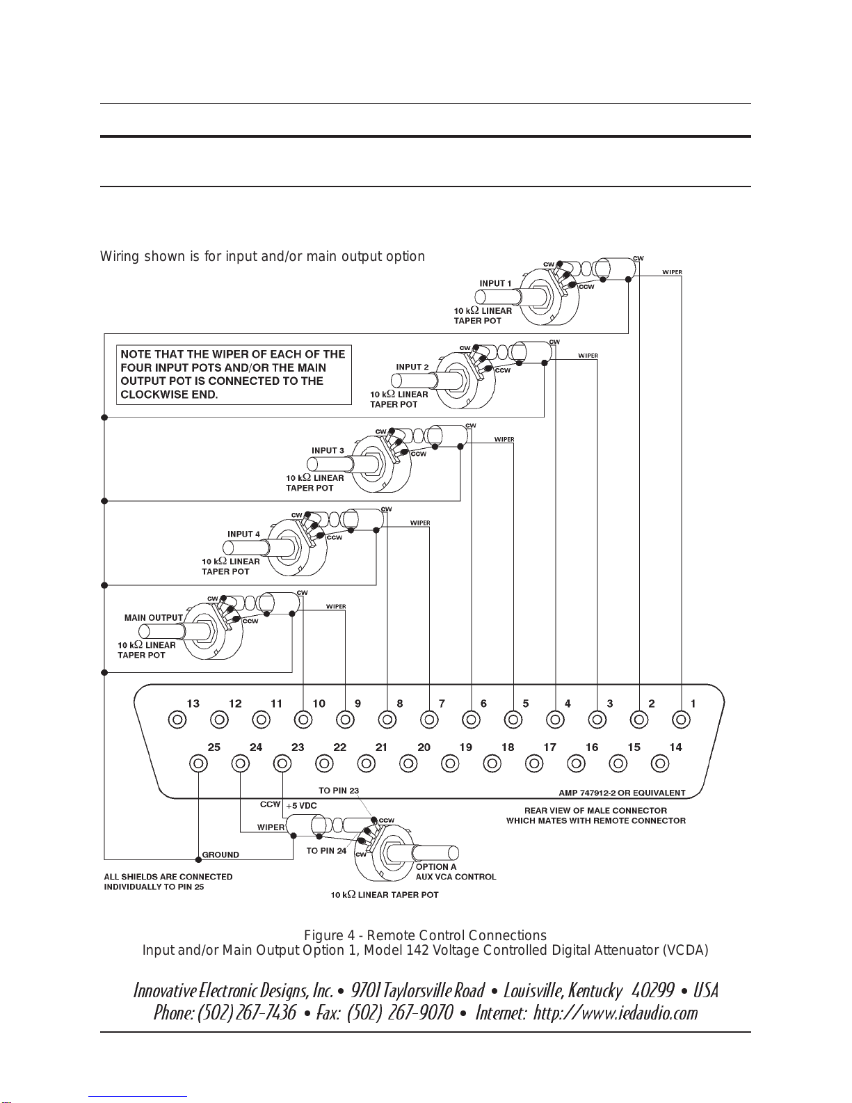
Figure 4 - Remote Control Connections
Input and/or Main Output Option 1, Model 142 Voltage Controlled Digital Attenuator (VCDA)
Wiring shown is for input and/or main output option 1,
110V Voltage Controlled Amplifier. Auxiliary Input VCA
option is Option A.Use 22 AWG twisted pair with overall
shield, Belden 8451 or equivalent.
REMOTE CONNECTOR, INPUT AND/OR MAIN OUTPUT OPTION 1 AND
AUXILIARY INPUT OPTION A

4400 AND 4800 SERIES MIXERS MAY 1999 SECTION 4GROUP 20 SUB BPAGE 7
INSTALLATION INSTRUCTIONS MODELS 4400 SERIES AND 4800 SERIES AUTOMATIC MIXERS
Figure 5 - Remote Control Connections, 120P Setup Control
Figure 6 - Remote Control Connections, Logic Output
INPUT AND/OR MAIN OUTPUT OPTION 2 AND LOGIC OUT

SECTION 4GROUP 20 SUB BPAGE 8MAY 1999 4400 AND 4800 SERIES MIXERS
MODELS 4400 SERIES AND 4800 SERIES AUTOMATIC MIXERS INSTALLATION INSTRUCTIONS
Innovative Electronic Designs, Inc. 9701 Taylorsville Road Louisville, Kentucky 40299 USA
Phone: (502) 267-7436 Fax: (502) 267-9070 Internet: http://www.iedaudio.com
hh
hh h
REMOTE CONNECTOR, INPUT AND/OR MAIN OUTPUT OPTION 1 USING
412PLCs FOR REMOTE LEVEL CONTROL
Figure 7 - Rear terminal connections
Input and/or Main Output Option 1 using 412PLC for remote level control
4400 AND 4800 SERIES MIXERS MAY 1999 SECTION 4GROUP 20 SUB BPAGE 9
INSTALLATION INSTRUCTIONS MODELS 4400 SERIES AND 4800 SERIES AUTOMATIC MIXERS
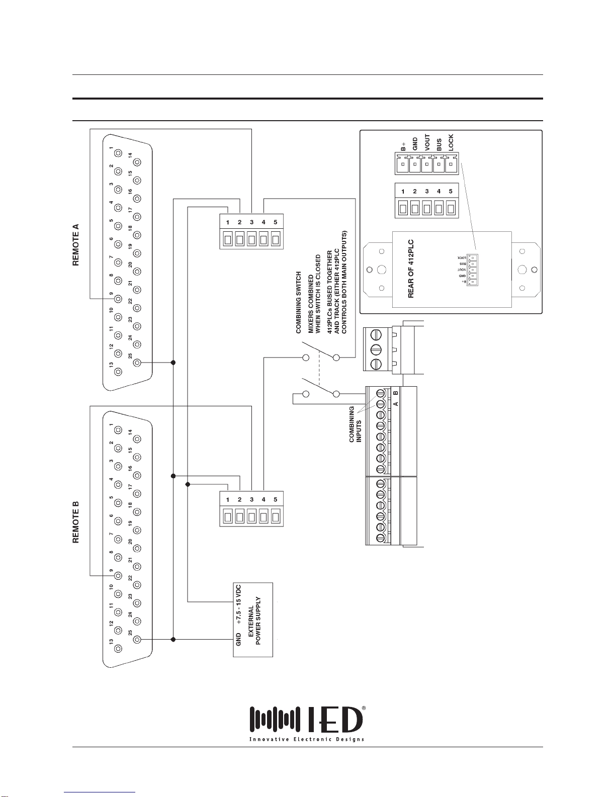
COMBINING SWITCH AND REMOTE OUTPUT LEVEL CONTROL USING 412PLC
Figure 8 - Rear terminal connections
Combining switch and remote output level control using 412PLC

SECTION 4GROUP 20 SUB BPAGE 10 MAY 1999 4400 AND 4800 SERIES MIXERS
MODELS 4400 SERIES AND 4800 SERIES AUTOMATIC MIXERS INSTALLATION INSTRUCTIONS
Innovative Electronic Designs, Inc. 9701 Taylorsville Road Louisville, Kentucky 40299 USA
Phone: (502) 267-7436 Fax: (502) 267-9070 Internet: http://www.iedaudio.com
hh
hh h
Figure 9 - Remote control connections
Force On
Figure 10 - Remote control connections
Force Off
REMOTE CONNECTOR FORCE ON/FORCE OFF

4400 AND 4800 SERIES MIXERS MAY 1999 SECTION 4GROUP 20 SUB BPAGE 11
INSTALLATION INSTRUCTIONS MODELS 4400 SERIES AND 4800 SERIES AUTOMATIC MIXERS
Figure 11 - Overall view of printed circuit board

SECTION 4GROUP 20 SUB BPAGE 12 MAY 1999 4400 AND 4800 SERIES MIXERS
MODELS 4400 SERIES AND 4800 SERIES AUTOMATIC MIXERS INSTALLATION INSTRUCTIONS
Innovative Electronic Designs, Inc. 9701 Taylorsville Road Louisville, Kentucky 40299 USA
Phone: (502) 267-7436 Fax: (502) 267-9070 Internet: http://www.iedaudio.com
hh
hh h
Figure 12 - Direct Output Level Controls
Either line or microphone level can be se-
lected for each Direct Output. An overall level
control for each output provides adjustment
from maximum to full off. As seen in the figure,
the level controls are located on the circuit
board near the back edge, just in front of the
screw terminal connector strip. The controls
areaccessablebyremoving thereartopcover
by loosening the thumb screws provided.
Level increases with clockwise rotation.
DIRECT OUTPUT LEVEL CONTROLS

4400 AND 4800 SERIES MIXERS MAY 1999 SECTION 4GROUP 20 SUB BPAGE 13
INSTALLATION INSTRUCTIONS MODELS 4400 SERIES AND 4800 SERIES AUTOMATIC MIXERS
Figure 13 - Gain adjustment of gated inputs
Jumper setup
GAIN ADJUSTMENT OF GATED INPUTS
Gated Inputs -The gainofgatedinputs as de-
livered from the factory is set at +35 dB. With
the proper jumpers installed, microphone
level gains between +26 dB and +46 dB
gains between +26 dB and +46 dB can be
achieved by adjusting the pot as shown. By
removing the jumper, a gain of 0 dB can be
achieved. Other gain values are possible by
changing SIP values. Consult the factory for
additional information.
The controls and jumpers are accessible by
loosening the thumb screws and removing
the rear top cover.
SECTION 4GROUP 20 SUB BPAGE 14 MAY 1999 4400 AND 4800 SERIES MIXERS
MODELS 4400 SERIES AND 4800 SERIES AUTOMATIC MIXERS INSTALLATION INSTRUCTIONS
Innovative Electronic Designs, Inc. 9701 Taylorsville Road Louisville, Kentucky 40299 USA
Phone: (502) 267-7436 Fax: (502) 267-9070 Internet: http://www.iedaudio.com
hh
hh h
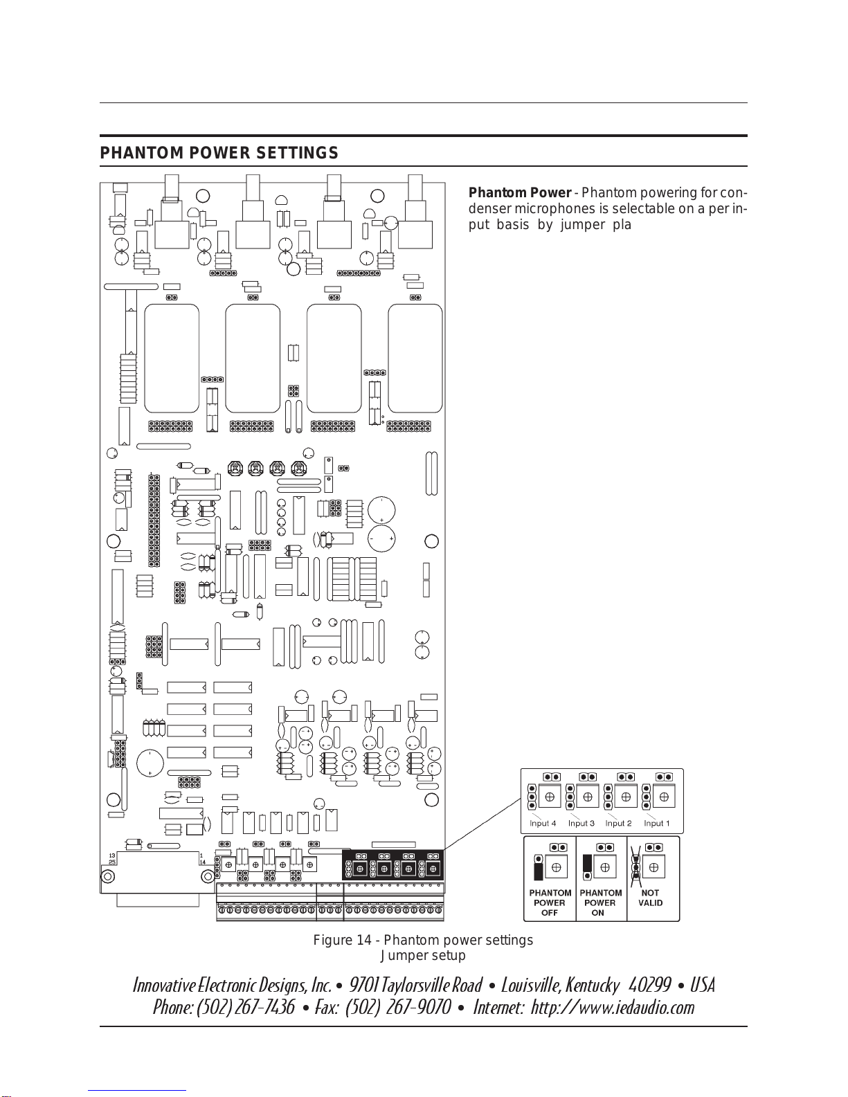
Figure 14 - Phantom power settings
Jumper setup
PHANTOM POWER SETTINGS
Phantom Power - Phantom powering for con-
denser microphones is selectable on a per in-
put basis by jumper placement. Phantom
power for the entire mixer may be turned ‘on’
or ‘off’ by a front panel switch. When the front
panel switch is in the ‘on’ position, only those
inputs which have their jumpers in the ‘on’ po-
sition will have phantom power available. A
jumper MUST be in place in either the ‘on’
or the ‘off’ position, or the input will be
open and floating, and susceptible to extra-
neous noise pickup. Phantom power jumper
positions are shown in the figure below. Phan-
tom power is provided to inputs from the 4822
card. +15 V is standard and +30/48 V can be
provided with the with the pahntom power op-
tion. See figure 31.
Phantom power jumpers are accessible by
loosening the thumb screws and removing
the rear top cover.
Phantom powering should be used for con-
denser microphones only. It should not be
used for dynamic microphones or line level
applications. As shipped from the factory, the
phantom powering jumpers are set to the ‘Off’
position (for line level or dynamic microphone
inputs).
CAUTION! Do not set phantom power
jumpers with power on. So doing incurs the
risk of damaging the inputs, and will void
the warranty.

4400 AND 4800 SERIES MIXERS MAY 1999 SECTION 4GROUP 20 SUB BPAGE 15
INSTALLATION INSTRUCTIONS MODELS 4400 SERIES AND 4800 SERIES AUTOMATIC MIXERS
Figure 15 - Enabling/disabling Priority of gated inputs
Jumper setup
ENABLING/DISABLING PRIORITY OF GATED INPUTS
Priority - Priority is the feature, which when
enabled for an input allows that input to take
precedenceover inputs which do not havethe
priority feature enabled. That is to say that
when an input in priority is gated on, other in-
puts not in priority are immediately caused to
gate off. Other inputs which are in priority are
notaffected. Toplaceaninput inpriority,place
a jumper on the appropriate pins as shown in
the figure below. As shipped from the factory,
no priority jumpers are in place, and no inputs
are in priority.
SECTION 4GROUP 20 SUB BPAGE 16 MAY 1999 4400 AND 4800 SERIES MIXERS
MODELS 4400 SERIES AND 4800 SERIES AUTOMATIC MIXERS INSTALLATION INSTRUCTIONS
Innovative Electronic Designs, Inc. 9701 Taylorsville Road Louisville, Kentucky 40299 USA
Phone: (502) 267-7436 Fax: (502) 267-9070 Internet: http://www.iedaudio.com
hh
hh h
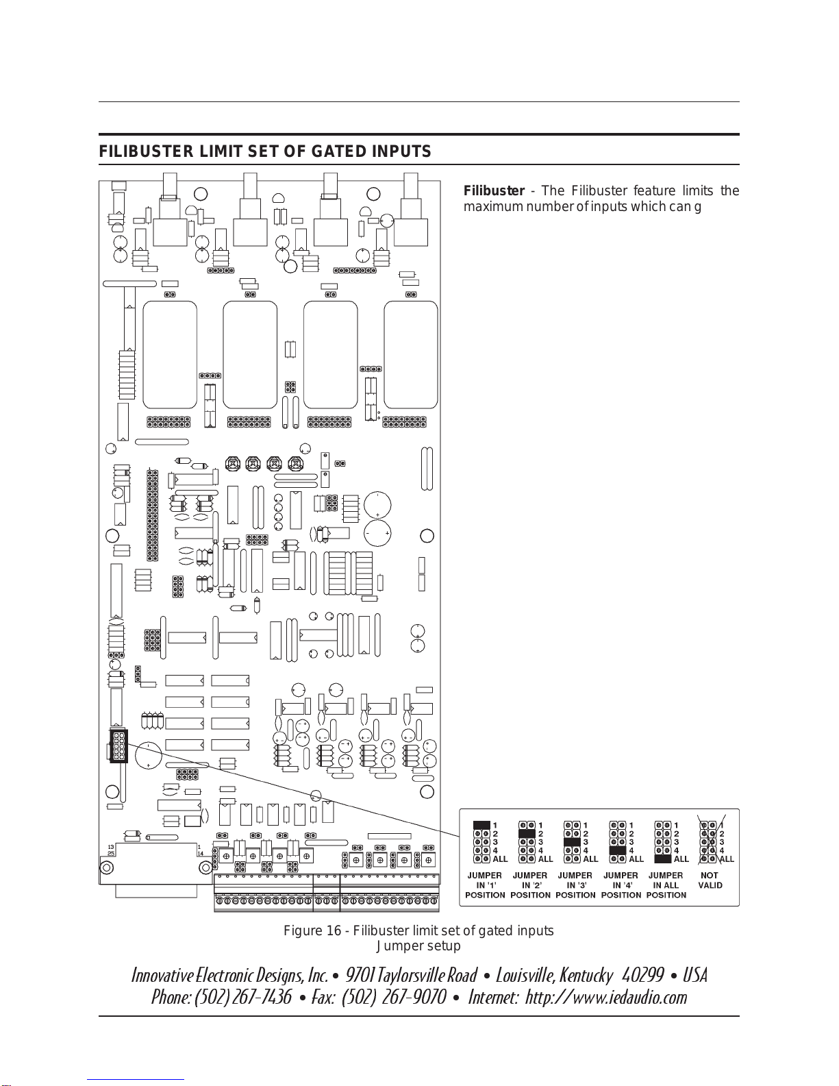
Figure 16 - Filibuster limit set of gated inputs
Jumper setup
FILIBUSTER LIMIT SET OF GATED INPUTS
Filibuster - The Filibuster feature limits the
maximumnumber ofinputswhich cangateon
in a given mixer. If the two 4-input mixers in a
4800 or 4800EQ are combined, the total num-
ber of inputs which are gated on in the com-
bined mixer count toward the limit. The limit
can be set at 1, 2, 3, 4, or ALL. The ALL setting
defeats the feature. If mixers are combined
and the limit on a particular mixer is set for 2,
an input on that mixer can gate on only when
the total number of inputs which are on on
bothmixers is less than 2. A jumper MUST be
placed in one, but not more than one of the
positions, or erratic performance may re-
sult. The figure below shows the details of
jumper placement. Inputs for which the Digital
Attenuator has been defeated do not contrib-
ute to or affect the Filibuster limit, although
they are still subject to it. As shipped from the
factory, there is a jumper in the ‘All’ position,
defeating the Filibuster feature and allowing
all inputs to be on.
4400 AND 4800 SERIES MIXERS MAY 1999 SECTION 4GROUP 20 SUB BPAGE 17
INSTALLATION INSTRUCTIONS MODELS 4400 SERIES AND 4800 SERIES AUTOMATIC MIXERS
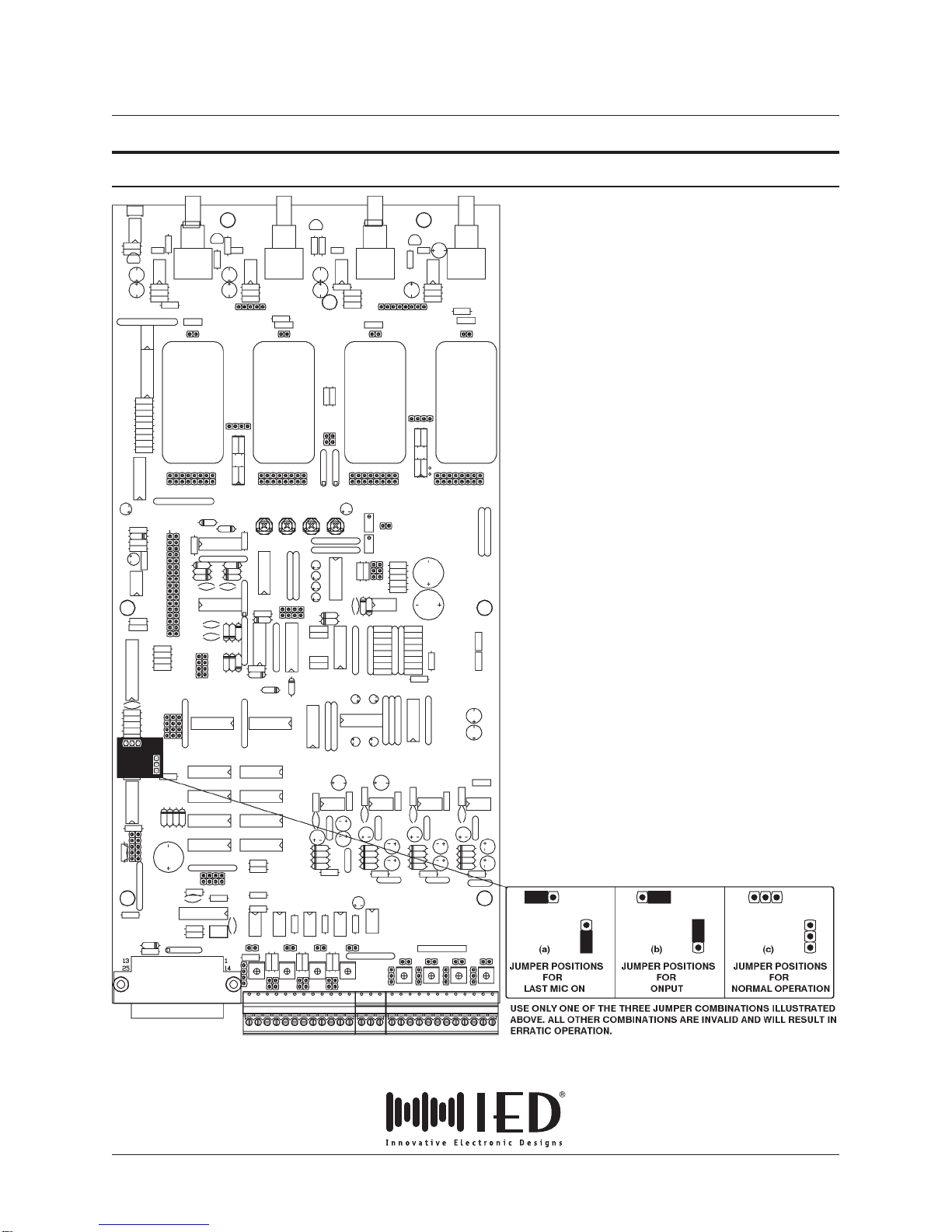
Figure 17 - Last Mic On and Onput for gated inputs
Jumper setup
Last Mic On - When the Last Mic On feature
is enabled, the last input which is gated on re-
mains on until another input is gated on in its
place. This feature prevents the system from
sounding ‘dead’ by always keeping one mi-
crophone on. The figure below shows the de-
tails of Last Mic On jumper placement. When
Last Mic On is used with a combined 8 input
mixer, jumpers must be placed on both input
boards in the Last Mic On position.
Onput - When the Onput feature is enabled,
input number 1 is gated on or remains on until
another input is gated on in its place. This fea-
ture prevents the system from sounding
‘dead’ by turning on the number 1 input when
allother inputs aregatedoff.Shownbeloware
the details of Onput jumper placement. When
using the Onput feature with a combined 8 in-
put mixer, Onput must be selected on only
one of the two input boards. If selected on the
‘A’ board, input 1 will gate on when all other
inputs gate off. If Onput is selected on board
‘B’ then input 5 will gate on when all other in-
puts gate off.
If neither Last Mic On nor Onput jumpers are
in place as in shown below, gated inputs will
gate off normally. Do not attempt to operate
the system with only one jumper in place or
with other jumper combinations. Erratic op-
eration will result.
As shipped from the factory, neither Last Mic
On nor Onput jumpers are in place (normal
operation).
LAST MIC ON AND ONPUT FOR GATED INPUTS

SECTION 4GROUP 20 SUB BPAGE 18 MAY 1999 4400 AND 4800 SERIES MIXERS
MODELS 4400 SERIES AND 4800 SERIES AUTOMATIC MIXERS INSTALLATION INSTRUCTIONS
Innovative Electronic Designs, Inc. 9701 Taylorsville Road Louisville, Kentucky 40299 USA
Phone: (502) 267-7436 Fax: (502) 267-9070 Internet: http://www.iedaudio.com
hh
hh h
Figure 18 - Force On and Force Off for gated inputs
Jumper setup
FORCE ON AND FORCE OFF FOR GATED INPUTS
Force On/Force Off - These functions over-
ride gating operation and place the input in a
continuous on state or a continuous off state,
respectively. When an input is forced on it still
contributes to the attenuation of the Main Out-
put(DigitalAttenuator),totheFilibustercount,
andtotheDiscriminator,unlessspecificallyre-
moved from these functions by defeating the
Digital Attenuator and/or the Discriminator
(see pages 22 and 23).
When an input is forced off, it is continuously
off and removed from the Discriminator, so
that a signal to the input will not affect the
gating of the other gated inputs.
For details of jumper setup, refer to the figure
below.
The 4400 and 4800 Series Automatic Mixers
are shipped from the factory with all inputs set
for normal gating (no jumpers installed).

4400 AND 4800 SERIES MIXERS MAY 1999 SECTION 4GROUP 20 SUB BPAGE 19
INSTALLATION INSTRUCTIONS MODELS 4400 SERIES AND 4800 SERIES AUTOMATIC MIXERS
Figure 19 - Digital Attenuator defeat for gated inputs
Jumper setup
DIGITAL ATTENUATOR DEFEAT FOR GATED INPUTS
Digital Attenuator Defeat - The Digital At-
tenuator makes adjustments in the main out-
put level as inputs gate on or off. For each
doubling of the number of inputs which are
on, the Main Output is attenuated 3 dB. This is
a measure to help control feedback.
If the inputs operate at the same level, and
since they are summed or added in the mix
bus, doubling the number of inputs would
double the output power, an increase of 3 dB.
By attenuating the output by 3 dB for each
doubling of the number of inputs, the output
level is kept approximately constant.
If an input is used for a source which is not in
the same acoustic environment such as a
source of background music or a microphone
which is in another room, it is desireable to
prevent it from contributing to the Digital At-
tenuator. As shipped from thefactory,jumpers
are installed on all inputs (normal operation).
To defeat the feed to the Digital Attenuator for
a particular input remove the the appropriate
jumper. Refer to the figure below for jumper
application details.
SECTION 4GROUP 20 SUB BPAGE 20 MAY 1999 4400 AND 4800 SERIES MIXERS
MODELS 4400 SERIES AND 4800 SERIES AUTOMATIC MIXERS INSTALLATION INSTRUCTIONS
Innovative Electronic Designs, Inc. 9701 Taylorsville Road Louisville, Kentucky 40299 USA
Phone: (502) 267-7436 Fax: (502) 267-9070 Internet: http://www.iedaudio.com
hh
hh h
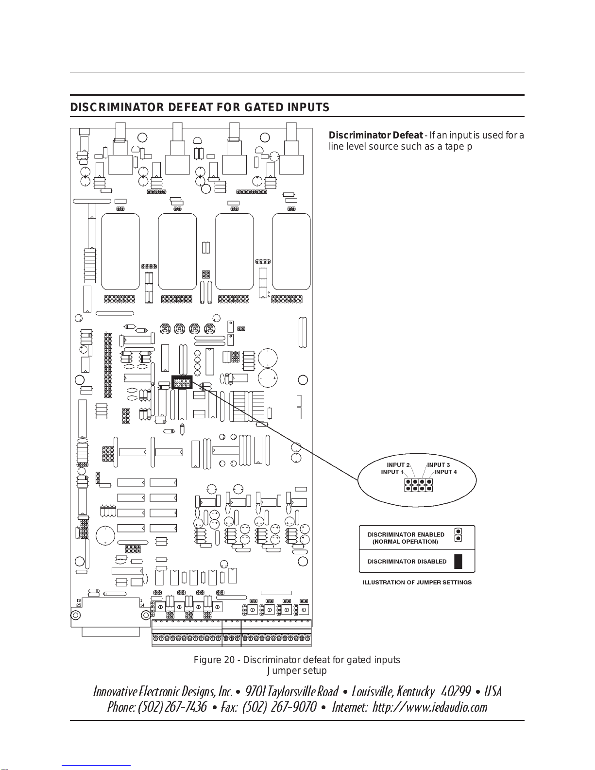
Figure 20 - Discriminator defeat for gated inputs
Jumper setup
DISCRIMINATOR DEFEAT FOR GATED INPUTS
Discriminator Defeat - If an inputisused for a
line level source such as a tape player, then it
isnotdesireableto haveitonthediscriminator
bus. A line level input could raise the level of
the discriminator threshold to such an extent
thatitwouldbeverydifficult togateonanother
gated input. For this reason, the Discriminator
Defeat has been provided. To defeat the
Discriminator function for an input, place a
jumper on the appropriate pins. When the
Discriminator has been defeated for a gated
input, it will no longer gate on in response to
an input signal. Instead, it must be Forced On
(seepage21).Thefigure below shows the de-
tails of jumper placement. As shipped from
the factory, the Discriminator is enabled (no
jumpers).
This manual suits for next models
1
Table of contents


