iNO IRXCAM INO160THz User manual

1of 9
IRXCAM INO160THz
160X120 Uncooled THz Bolometric Camera
User Manual
INO
2740, rue Einstein
Sainte-Foy, QC, G1P 4S4 Canada
Tel.: 418-657-7006
Fax: 418-657-7009
July 2010
Proprietary Notice:
Details of design and engineering are the exclusive property of INO and other partners,
and are strictly confidential. The information given herein is subject to change at any
time and without notice.
All rights are reserved. The information included in this document may not be reproduced
or passed on in any manner without prior consent of INO.

2of 9
General Description
The aim of this manual is to present the procedure of installation and associated
precautions to take when using the IRXCAM INO160THz camera module. The technical
specifications and examples of THz imaging are also provided. This document contains
general information about the product, as well as recommendations for its use.
The IRXCAM camera module is based on an uncooled bolometric sensor specially
designed to provide high sensitivity imaging in the terahertz region (optimized at 100 m
wavelength or 3 THz) from a 160X120 focal plane array (FPA) sensor. This module is
designed specifically for developers and integrators. It provides the raw data of the digital
sensor (16-bit, 30 frames per second). The user is then able to select the most appropriate
post-processing treatment method depending on the application. The IRXCAM camera
module provides real-time access to sensor parameters. The user can define the
observation window or adjust the gain and integration time to the dynamic range of the
scene.
The IRXCAM camera module is simple and easy to operate. All functions are controlled
via the IRXCAM software. The starting procedure includes connections between the
camera and the computer via the RJ-45 Ethernet cable, and the +12VDC power supply
and the camera. The user should allow a few minutes for the module warm up before
launching the IRXCAM software. An image is automatically displayed at the startup. It is
obtained from current raw data and last active gain correction, pixel replacements and
offset table.

3of 9
Technical Specifications
Sensor INO160THz
Microbolometer uncooled FPA bolometer
160X120 pixels, 52 m pitch
Optimized metallic FPA package
Silicon float zone FPA window
Optimized for 3 THz (100 m wavelength)
Ceramic Gen II vacuum microbolometer package
Video Output Gigabit Ethernet Link
RJ-45 connector
16 bit raw data
Control Gigabit Ethernet Link
System operation control
Loading of parameters & calibration tables
FPA Operability > 99.9%
Frame Rate 30 Hz
Available Options External trigger input (opto-isolated)
TEC driver
Random access readout
Mechanical support (DEV)
Power Supply +9 to +12 Volts DC
Power Consumption With GigE Link: < 4 Watts
Overall Dimensions 65 mm (H) X 59 mm (W) X 105 mm (L)
Weight ~500 g
Temperature Operating: –30°C to 55°C
Storage: –40°C to 80°C
4of 9
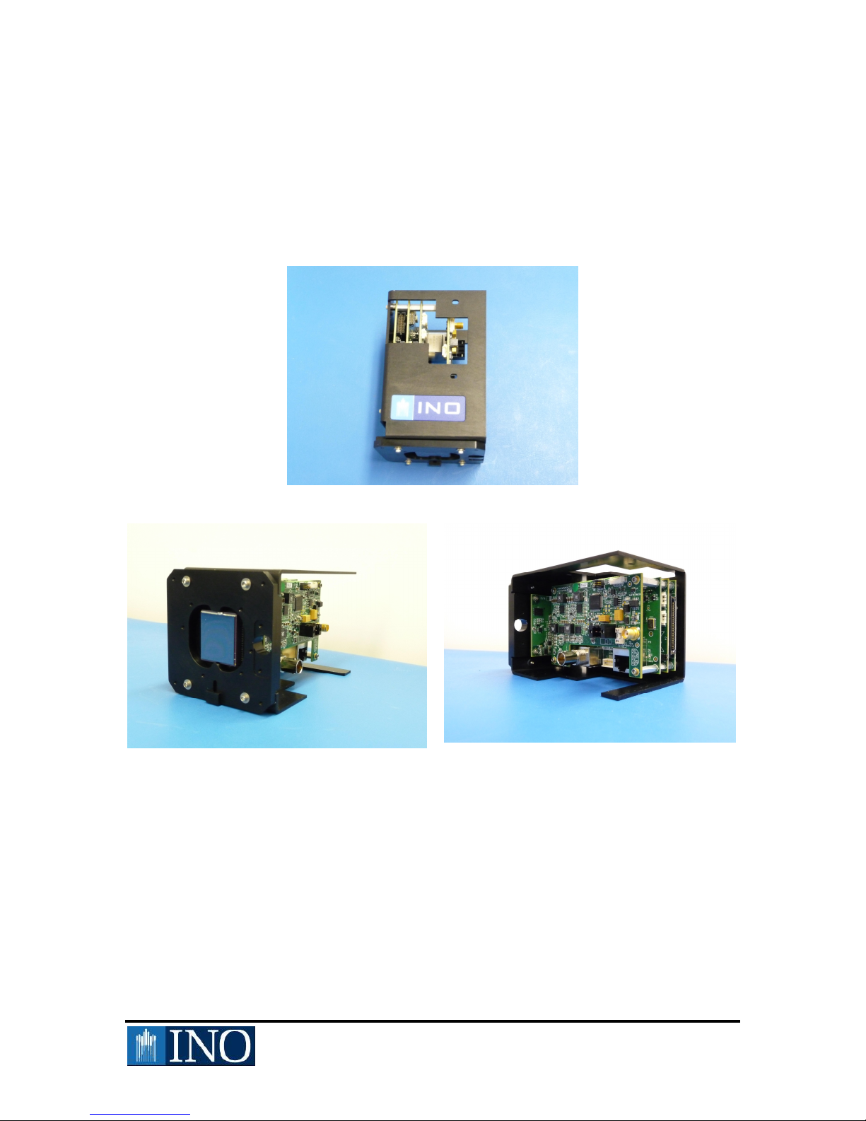
Camera Hardware
The IRXCAM camera module consists of a sensor assembled to an electronic proximity.
The sensor is a sealed box under vacuum containing a microbolometer detector array size
160X120, named INO160THz.The camera assembly is presented in Fig. 1
Fig. 1 IRXCAM Camera Module
5of 9
General Warnings
The IRXCAM camera module is sensitive to electrostatic discharge (ESD). The
following precautions should be taken before handling the camera in order to prevent
possible damage to the equipment.
ESD SENSITIVE
Workstation setup for device utilization:
Choose a place away from the hallway.
Make sure the workstation is in accordance with level ESD Class 1, according to
NASA-8739.7.
Install a ground guard.
Ground all electrical tools and testing equipment.
Wear an ESD smock, nitrile gloves and/or an antistatic bracelet.
6of 9
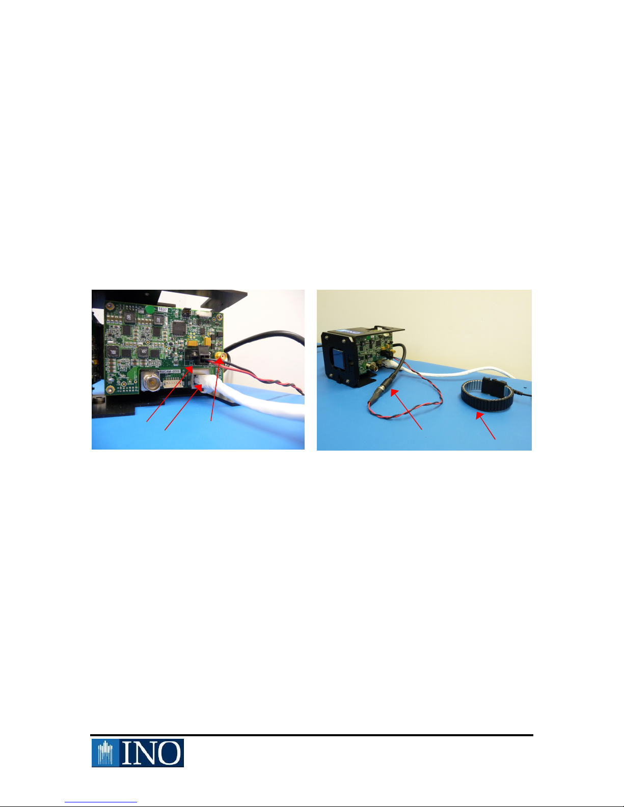
Hardware Installation
The hardware installation can be done once all ESD precautions have been taken. The
electronic module has two outputs and one input connector numbered in Fig. 2.
(1) Power connector
(2) RJ-45 Ethernet data communication connector
(3) SMA input trigger gold-coated connector
The black and red (4) power cable should be connected via a standard power pack. It is
important to remember that an (5) antistatic bracelet should be worn when plugging in
and manipulating camera hardware.
Fig. 2 IRXCAM Interconnections to External Components
All other connectors are not functional with the INO160THz sensor. Note that the
IRXCAM module has been developed to adapt to different INO sensors.
Software Installation
Please refer to the IRXCAM Control Application Software User Manuel.
(1)
(
2
)
(
3
)
(
4
)
(
5
)

7of 9
THz Characterization Setup
The IRXCAM-INO160THz camera module has been tested on a THz characterization
setup (presented in Fig. 3). The THz beam is emitted from a liquid-nitrogen cooled
pulsed quantum cascade laser (QCL) from Laser Components GmbH emitting at a
wavelength of 100 m. The camera module is placed at about 30 cm in front of the THz
QCL source, while a custom silicon float zone THz objective is placed in front of the
QCL for focusing the laser onto the detector. The main characteristics of the custom THz
objective and the THz source are presented in Table 1. The QCL beam has a large
divergence of about 22° involving the use of an optical objective or series of lenses for
collecting and focusing the emitted radiation onto the INO160THz FPA sensor. Note that
the custom objective is usually utilized in front of the camera for imaging applications.
Fig. 3 THz Characterization Setup

8of 9
The nominal peak power of the THz source is about 120 W with 10 sec pulse length.
The duty cycle of the pulsed AVTECH-1011 controller has been set to 10%, yielding an
average power of about 12 W. By considering the transmission value of 65% for the
quartz window and the refractive silicon float zone custom objective in front of the QCL,
the average output power may reach up to 8 W.
Custom THz Objective
Number of lenses 2
Lens material HRFZ-Si
AR coating (thickness) Parylene C (15 m)
Focal length 44 mm
F number 0.95
Aperture stop External, fixed diameter
Object distance 30 cm to infinity
Dimension = 80 mm; length = 60 mm
THz Source
Type Quantum Cascade Laser
Peak power 120 W
Repetition rate 10 kHz
Duty cycle 10%
Average power 12 µW
Pulse duration 10 sec
Central wavelength 100 m
Table 1. Main Characteristics of Custom THz Objective and QCL THz Laser

9of 9
Some images of the QCL beam are presented in Fig. 4. The QCL beam images have been
taken with the IRXCAM-INO160THz camera module. The high level of sensitivity may
be qualitatively seen. The z-scale represents the number of count while the x-y scalesare
the 160X120 pixels number.
Snap_2010-07-07_16-54-50.0891.bmp
Snap_2010-07-07_17-08-05.0280.bmp
Fig. 4Imagesof the QCL Beam Taken with the THz Optimized FPA Mounted on the
IRXCAM Camera Module
Note that the difference between images above is mainly due to the adjusting contrast and
brightness values from the IRXCAM software. The advanced IRXCAM device settings
used for imaging the THz QCL beam are presented in Table 2. Note that all bias voltages
given in Table 2 are given in milliVolts.
Advanced Parameters
VBPIXEL (mV) 1000
VBREF (mV) 1500
VBLINE (mV) 2500
VOUT_CM (mV) 2500
Table 2. IRXCAM Bias Voltage
Table of contents
Popular Digital Camera manuals by other brands

Sony
Sony DSC S650 - Cyber-shot Digital Camera instruction manual

Olympus
Olympus FE 120 - Digital Camera - 6.0 Megapixel quick start guide

Moultrie
Moultrie A-5 user manual

Garmin
Garmin BC installation instructions

JAI
JAI TM-6760 Series Operation manual

Panasonic
Panasonic Lumix DMC-FS5 operating instructions


